

Page 1
12/7/05 Rev. 1/31/2012 09-126-120.doc
O
VESTIL MANUFACTURING CORP.
2999 N. Wayne St., Angola, IN 46703
Ph: 260-665-7586 · Fax: 260- 665-1339
E-mail: sales@vestil.com
Assembly / Installation Instructions ………………..… 2
Ope
ration Instructions ……………………….……….. 2 - 3
Routine Maintenance & Safety Checks ………………. 3
Exploded Structural Parts Drawing & BOM ………..... 4 - 6
· www.vestil.com
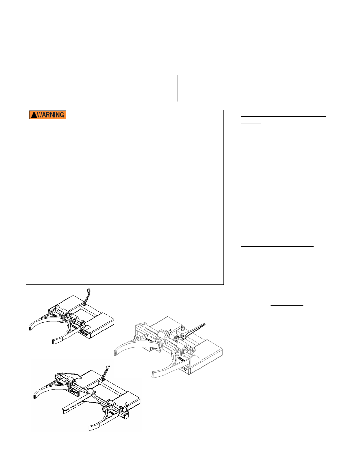
MODEL DGD-A, DGS-A, & DGS-AG
Troubleshooting …………………………....…………. 3
Center of Gravity diagrams……………………………. 7
Safety Label Identification .............................................8
Warranty …………………………………….……..…. 9
Material handling is dangerous. To reduce the likelihood of
serious personal injury, each person who might use or maintain this
product should:
o Read and understand the owner’s manual before using or performing
maintenance on the drum handler.
o Unload the handler before maintaining/servicing the handler.
o DO NOT use the handler unless all labels shown on p. 7 are in place
and readable.
o DO NOT use the handler if any damage or unusual movement is
observed, or if it seems to be malfunctioning. Notify your supervisor
or maintenance personnel if you notice anything out of the ordinary.
o Always watch the drum grippers and the drum carefully while using
the drum handler.
o Before transporting a drum, elevate the forks sufficiently to raise
the drum a few inches off of the ground. Transport the drum as
close to the ground as possible.
o DO NOT exceed the maximum rated load of your model drum
handler. The load rating, in pounds, is shown on the machine data
plate. It indicates the net capacity of the drum handler with a
static load that is centered and evenly distributed.
o Keep all personnel clear of the machine when it is in operation.
o Only use DGS-A and DGD-A units to lift and transport steel drums.
o DO NOT modify the handler unless you are CERTAIN that the handler
will be safe to use afterwards. Any modification automatically voids
the limited warranty.
DG
DGD
S-A
DGS-AG
-A
WNER’S
MANUAL
TO ORDER REPLACEMENT
PARTS:
We take pride in using quality
parts on the equipment we
manufacture. We are not
responsible for equipment
problems resulting from the use
of unapproved replacement
parts.
To order replacement or
spare parts for this equipment,
contact the factory.
In any communication with
the factory please be prepared
to provide the machine’s serial
number, which is indicated on
the machine dataplate.
RECEIVING INSTRUCTIONS
It is possible that the unit could
incur damage during transit.
Inspect the unit closely when
it arrives. If you see evidence
of damage or rough handling to
either the packaging or to the
product when it is being
unloaded, immediately
note of it on the Bill Of Lading!
It is important that you
remove the product’s packaging
upon its arrival to ensure that
there is no concealed damage
or to enable a timely claim with
the carrier for freight damage.
o verify that the product
Als
and its specifications are as
ordered.
make a
V
ESTIL MFG. CO./T&S EQPT. CO. 1 of 9
Page 2
12/7/05 Rev. 1/31/2012 09-126-120.doc
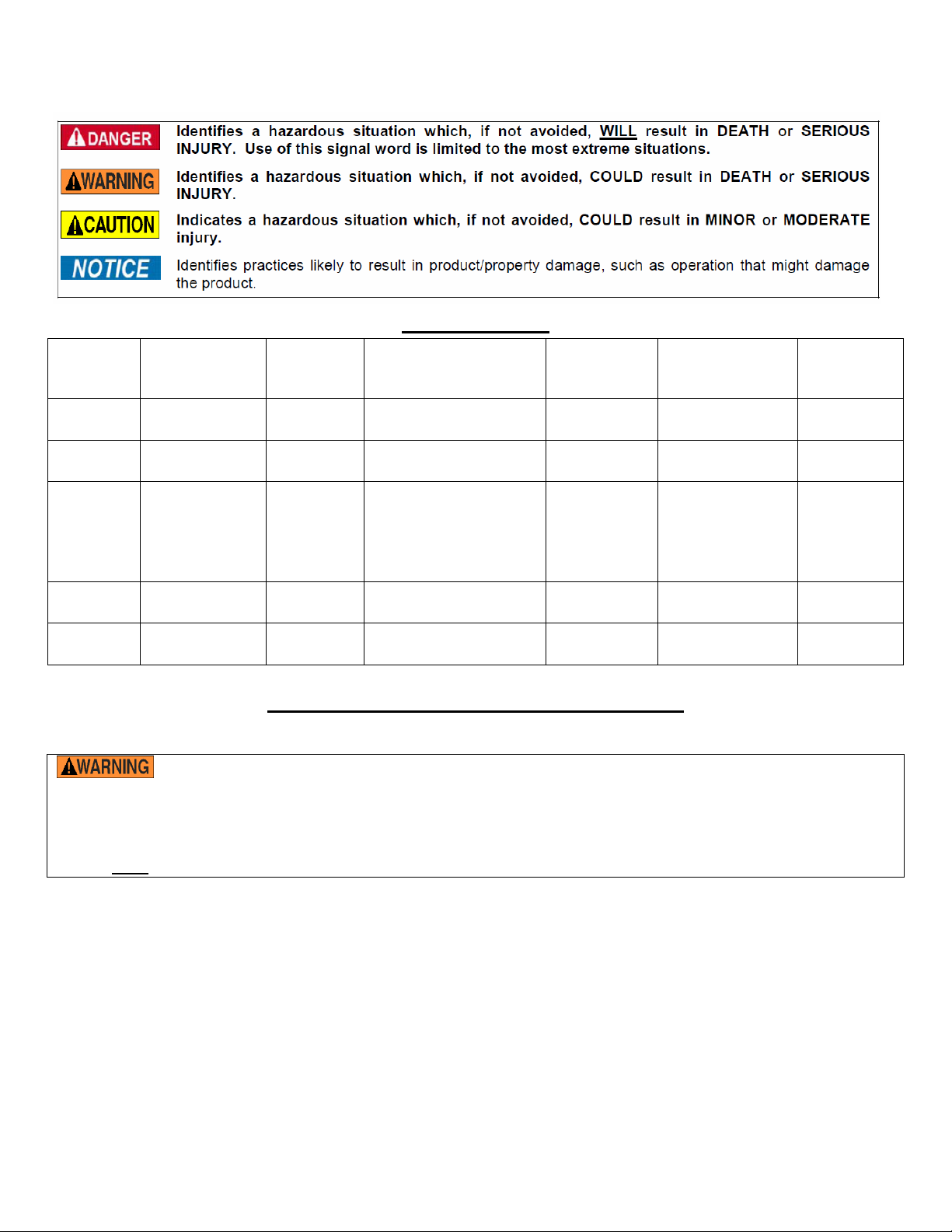
This manual uses SIGNAL WORDS to classify personal injury risks or situations that might lead to property damage,
as well as to draw attention to safety messages. The reader must understand that each signal word indicates the
seriousness of the described hazard.
SPECIFICATIONS
NIFORM
U
CAPACITY IN
POUNDS
800 26
VERALL DIMENSIONS
O
(WXDXH) IN INCHES
IN. X 35IN. X 8IN. 19¾IN. 7¼IN. X 2½IN.
ODEL
M
DGS-A
D
RUM VOLUME AND
MATERIAL
30
GAL. & 55 GAL.
STEEL
DGS-55-D 55 GAL. STEEL 1,500 28¼IN. X 24IN. X 8IN. 13½IN. 6¼IN. X 2IN.
1,500
FIBER)
1,000
34
1
1,500 45
/
IN. X 28IN. X 9½IN. 19¼IN. 5
8
IN. X 36IN. X 8IN. 24IN. 7¼IN. X 2½IN.
DGS-AG
DGD-A
AL.; 55GAL.;
30G
85GAL.
STEEL
IBER
F
PLASTIC
30
GAL. & 55 GAL.
STEEL
(STEEL &
(PLASTIC)
DGD-55-D 55GAL. STEEL 2,000 46IN. X 24¼IN. X 9½IN. 24IN. 7¼IN. X 2½IN.
ORK POCKET
F
CENTERS IN
POUNDS
ORK POCKET
F
DIMENSIONS (WXH)
IN
INCHES
5
/
IN. X 1
8
5
/
IN.
8
ET WEIGHT
N
POUNDS
IN
105
(47.7KG)
109
(49.5KG)
130
(59.1
96
(43.6KG)
185
(84.1KG)
KG)
OPERATION INSTRUCTIONS – DGD-A / DGS-A
The standard model DGD-A / DGS-A is suitable for lifting and transporting open or closed standard 30 gallon and 55-
gallon steel drums in most (non classified) industrial locations which do not involve hazardous materials.
DO NOT exceed the DGD-A / DGS-A’s load ratings. Injury to personnel or permanent damage to the
loading arms, the drum(s), or drum contents, could result from exceeding the listed capacity.
All persons involved in the use of this drum handler should read and apply these instructions!
Inspect the safety chain and lifting arms daily.
Although your drum handler can lift loads equal to or less than its uniform capacity (see “Specifications” above),
the drum itself (lip or rim) must be capable of supporting the full weight of the load as well.
1.) Adjust the forks so that the inside width between the forks will fit into the fork pockets.
2.) Drive the truck forward to slip forks into the fork sleeves. Attach safety chain the mast to secure drum lifter to
forks.
3.) DGD-A & DGS-A: Raise and tilt the forks forward to separate the arms slightly
DGS-AG: Raise the forks and adjust the tilt so that the gripper arms are parallel to the floor. The left and right
side gripper cast brackets (item numbers 13 & 14 on p. 6) must not contact the cross support of the frame (see p.
6), because contact will prevent the gripper from moving properly. Adjust the tilt of the forks so that the cast
brackets do not contact the cross-support. Ratchet the gripper arms apart sufficiently so that a drum will fit
between them. NOTE: You will have to grasp the shaft of the load binder (see p. 6) for the ratchet to function.
4.) DGD-A & DGS-A: Lower the gripper arms over the top of the drum until the arms are at the desired lifting point
on the drum.
DGS-AG: Drive the fork lift toward the drum and adjust the height of the forks so that the gripper arms will be
just below the ridge of the dr um. Dr ive th e fork lift for ward until the drum presses against the backs of the gripper
arms. Ratchet the gripper arms together until they firmly contact the sides of the drum just below the ridge. NOTE:
V
ESTIL MFG. CO./T&S EQPT. CO. 2 of 9
Page 3

12/7/05 Rev. 1/31/2012 09-126-120.doc
Be very careful not to over-tighten the grippers when using this device to engage plastic or fiber drums. Overtightening the grippers might crack or puncture the drum.
5.) DGD-A & DGS-A: Raise the forks and tilt them back. Adjust the elevation of the drum so that it is as close to the
floor as possible while transporting it.
DGS-AG: Elevate the forks sufficiently to raise the drum a few inches from the ground, and transport the drum to
the desired location.
6.) To release the drum, tilt the forks forward, lower drum to the ground and back away from the drum.
R
OUTINE MAINTENANCE & SAFETY CHECKS – _DGD-A / DGS-A
: Identify all potential hazards and comply with applicable safety procedures before beginning work.
Only qualified individuals trained to understand mechanical devices and their associated hazards should attempt
troubleshooting and repair of this equipment.
(A) Before each use inspect for the following:
1.) Damage or structural deformation to the structural members, the fork tubes, lifting arms, retaining/safety
chain & bracket etc.
2.) Unusual noise or binding, or evidence thereof.
3.) Proper functioning of the lock.
4.) Apparent damage or fatigue to the safety, strap / chain (used to secure the drum gripper to the fork truck
mast), or to the safety latch at the end of the strap / chain.
(B) Inspect monthly for:
1.) Pivot point wear.
2.) Integrity of the retaining hardware on all pivot point pins.
3.) The integrity of the hook, chain and chain retaining brackets.
4.) Looseness, wear, or damage to the drum lifting arms.
5.) Unusual noises or movement during operation.
6.) Signs of excessive wear, or damage to any part of the safety strap, including the strap hooks safety latch.
7.) All the information, safety, and warning labels being in place and in good condition.
8.) The need to clean off dirt and debris.
(C) Yearly inspection
1.) Test the drum gripper under full load. Remove the drum(s) and inspect all of the welds for cracks and the
structural parts for signs of fatigue or deformation.
TROUBLESHOOTING GUIDE -- ______
Warning: Before performing any repair or trouble shooting task, always unload the drum handler.
Contact the factory for assistance with any problems not addressed below.
Problem: Possible cause(s): Action:
Drum won’t fit between the gripping
arms.
Drums slip out of the gripping arms
when lifted.
Gripping arms adjusted for smaller drum.
Drum is not a standard size drum.
Wrong size or type of drum
Arms or center support not in place
properly.
Readjust gripping arms.
Adjust/tilt the mast of the fork
truck forward to separate the arms.
Tilt the mast of the fork truck back
Gripping arms are not parallel.
V
ESTIL MFG. CO./T&S EQPT. CO. 3 of 9
Locking tabs are not secured in locking
slots
Debris/obstruction
Damage or structural deformation
Move gripping arms until locking
slots match locking tabs. Rotate
gripping arm down to insert locking
tab into locking slot.
Page 4

12/7/05 Rev. 1/31/2012 09-126-120.doc
EXPLODED PARTS VIEW AND BILL OF MATERIALS – DGS-A
V
ESTIL MFG. CO./T&S EQPT. CO. 4 of 9
Page 5

12/7/05 Rev. 1/31/2012 09-126-120.doc
EXPLODED PARTS VIEW AND BILL OF MATERIALS – DGD-A
V
ESTIL MFG. CO./T&S EQPT. CO. 5 of 9
Page 6

12/7/05 Rev. 1/31/2012 09-126-120.doc
EXPLODED PARTS VIEW AND BILL OF MATERIALS – DGS-AG
Item no.
Engineering
part no.
Description Quantity
1 40-514-060 Frame weldment 1
2 40-514-016 FMDL-series arm casting frame 2
3 15-112-014 1in. x 4½in. long retaining pin 2
4 65125 3/
in. x 1½in. zinc-plated cotter pin 6
16
5 40-514-059 Come-along post gripper bracket weldment 1
6 30-001-213-001 Load binder without hooks 1
7 40-112-013 Gripper guide pin 1
8 40-113-009 Shim/spacer 2
9 33018 ¾ in. zinc-plated USS flat washer 6
10 40-146-003 Spring 2
11 40-537-007 Spring stopper weldment 2
12 36109 ½ in. -13 UNC hex nut 4
13 40-516-009 Left side gripper casting bracket 1
14 40-516-010 Right side gripper casting bracket 1
Cross-support
Close-up of ratchet mechanism
Press the ratchet cam forward (see
the arrow in the graphic above; might
have to hammer it loose); then ratchet
the drum grippers open to release the
drum.
Grasp the shaft of the load
binder while ratcheting the
handle to prevent the shaft
from rotating.
V
ESTIL MFG. CO./T&S EQPT. CO. 6 of 9
Page 7

12/7/05 Rev. 1/31/2012 09-126-120.doc
CENTER OF GRAVITY VIEW– DGS-A
Horizontal Center of Gravity: 15 3/4”
Vertical Center of Gravity: 3”
Weight (Lost Load): 96 lbs
Effective (unit) Thickness: Fork Length minus 16”
CENTER OF GRAVITY VIEW– DGD-A
rizontal Center of Gravity: 18 3/4”
Ho
Vertical Center of Gravity: 3 1/2”
Weight (Lost Load): 136 lbs
Effective (unit) Thickness: Fork Length minus 16”
V
ESTIL MFG. CO./T&S EQPT. CO. 7 of 9
Page 8

12/7/05 Rev. 1/31/2012 09-126-120.doc
SAFETY LABEL IDENTIFICATION
Periodically inspect the labels on the drum handler should. Clean the labels to the extent necessary to maintain good
legibility from a reasonable viewing distance. Replace any label that is damaged. Contact the manufacturer for
replacement labels.
V
ESTIL MFG. CO./T&S EQPT. CO. 8 of 9
Page 9

12/7/05 Rev. 1/31/2012 09-126-120.doc
LIMITED WARRANTY
Vestil Manufacturing Corporation (“Vestil”) warrants this product to be free of defects in material and workmanship during
the warranty period. Our warranty obligation is to provide a repla
by the warranty, after we receive a proper request from the warrantee (you) for warranty servi ce.
cement for a defective original part if the part is covered
Who may request service?
Only a warrantee may request service. You are a warrantee if you purchased the product from Vestil or from an
authorized distributor AND Vestil has been fully paid.
What is an “original part”?
An original part is a part used to make the product as shipped
to the warrantee.
What is a “proper request”?
A request for warranty service is proper if Vestil receives: 1) a photocopy of the Customer Invoice
shipping date; AND 2) a written request
for warranty service including your name and phone number. Send requests by
that displays the
any of the following methods:
Mail
Fax Email
Vestil Manufacturing Corporation (260) 665-1339 sales@vestil.com
2999 North Wayne Street, PO Box 507 Phone
Angola, IN 46703 (260) 665-7586
In the written request, list the parts believed to be defective and include the address where replacements should be
delivered.
What is covered under the warranty?
After Vestil receives your request for warranty service, an authorized representative will contact you to determine whether
your claim is covered by the warranty. Before providing warranty service, Vestil may require you to send the entire
product, or just the defective part or parts, to its facility in Angola, IN. The warranty covers defects in the following original
dynamic
original
and batteries.
components: motors, hydraulic pumps, electronic controllers, switches and cylinders. It also covers defects in
parts that wear under normal usage conditions (“wearing parts”), such as bearings, hoses, wheels, seals, brushes,
How long is the warranty period?
The warranty period for original components is 90 days
. The warranty period begins on the date when Vestil ships the
product to the warrantee. If the product was purchased from an authorized distributor, the period begins when the
distributor ships the product. Vestil may extend the warranty period for products shipped from authorized distributors by
up to 30 days to account for shipping time.
If a defective part is covered by the warranty, what will Vestil do to correct the problem?
Vestil will provide an appropriate replacement for any covered part. An authorized representative of Vestil will contact you
to discuss your claim.
What is not covered by the warranty?
1. Labor;
2. Freight;
3. Occurrence of any of the following, which automatically voids the warranty
:
Product misuse;
Negligent operation or repair;
Corrosion or use in corrosive conditions;
Inadequate or improper maintenance;
Damage sustained during shipping;
Accidents involving the product;
Unauthorized modifications
: DO NOT modify the product IN ANY WAY without first receiving written
authorization from Vestil. Modification(s) might make the product unsafe to use or might cause excessive
and/or abnormal wear.
Do any other warranties apply to the product?
Vestil Manufacturing Corp. makes no other express warranties. All implied warranties are disclaimed to the extent allowed
by law. Any implied warranty not disclaimed is limited in scope to the terms of this Limited Warranty.
ESTIL MFG. CO./T&S EQPT. CO. 9 of 9
V
 Loading...