

Page 1
Edition of:
USERS O
October 15
CHUTES
MANUAL
FOR THE SUPERCHUTE DEBRIS CHUTE SYSTEM
When properly used, meets OSHA 1926.852 and CCMC 12270-R
• tel: 800-363-2488 • internet: www.superchute.com
• tel: 514-365-6121 • e-mail: info@superchute.com
• fax: 514-365-8987 • address: 8810 Elmslie Rd, Montreal, QC, Canada, H8R 1V6
• This edition of the “Chutes Manual” contains important new information.
• The instructions within are current and supersede any instruction found in a prior edition.
th
, 2001
• Avoid confusion: discard old instruction booklets concerning chute section installation.
Old booklet titles: “Installation Manual”, or “Safety Pack”, or “Chutes Manual”.
• If at any time you are unsure of how to proceed please call Superchute® toll free:
IT IS THE RESPONSIBILITY OF COMPANIES THAT SELL, RENT OR USE THE SUPERCHUTE®
PRODUCT TO FREELY SUPPLY THIS MANUAL TO THE FOLLOWING PERSONS:
• THE PLANNERS AND SUPERVISORS OF THE CHUTE SYSTEM
• THE INSTALLERS OF THE CHUTE SYSTEM
• THE
1-800-363-2488
F THE CHUTE SYSTEM
Page 2
• The installation and use of a Superchute® chute system involves work at
heights, suspended loads of considerable weight, and falling debris.
• Serious injury or death can result from improper installation, use, or
maintenance of the Superchute® product.
• Before the chute system is rigged or used, the following persons must read
and understand the instructions contained in this manual:
• If one or more Superchute® chute hoists will be used in the chute system,
then the above mentioned persons must also read and understand the
applicable “Chute Hoist Installation Manual(s)”.
1. The planners and supervisors of the chute system
2. The installers of the chute system
3. The users of the chute system
!
WARNING
If you have any questions or comments concerning this manual, please feel free
to contact Superchute Ltd.
The contents of this manual remain the intellectual property of Superchute
Ltd. Superchute Ltd. authorizes reproduction (photocopies or similar) of all
of its safety manuals, provided the reproduction is intended for users of the
Superchute
This manual refers to the following products, which are protected by international patent laws:
®
product. Reproductions must be made in their entirety.
© Superchute Ltd., 1999
Door Sections
U.S. Pat. No. Des. 328,174
Can. Ind. Des. 1990 RD 66842
Wraparound
Regular Sections
U.S. Pat. 5,472,768
Can. Pat. Application 2,119,108
U.K. Pat. 2,276,151
®
(Bolt-Downs, Roofers, Hoisters)
Can. Pat. Application 2,177,741
Chute Hoists
U.S. Pat. 5,934,437
All Rights Reserved
Printed in Canada
1 Help Line: 800-363-2488 October 15th, 2001
Page 3

Table of Contents
Page
1. GLOSSARY ............................................................................................................................................ 3
2. WARNING ELEMENTS ............................................................................................................................. 4
THE SAFETY ALERT SYMBOL ................................................................................................ 4
SIGNAL WORDS ................................................................................................................... 4
WARNING FORMAT .............................................................................................................. 5
3. IMPORTANT INFORMATION..................................................................................................................... 6
4. CHUTE SECTIONS................................................................................................................................... 7
5. THE CABLE ASSEMBLY ........................................................................................................................... 8
THE VITAL COMPONENT ....................................................................................................... 8
STRENGTH OF THE CURRENT CABLE ASSEMBLY .................................................................... 9
NEW HEIGHT & WEIGHT LIMITS OF CHUTE SECTIONS........................................................... 10
WHY IS WIRE ROPE USED IN THE CABLE ASSEMBLY? ........................................................... 11
ATTACHMENT TO THE CHUTE WALL ................................................................................... 12
MAINTENANCE................................................................................................................... 14
CAUTION! .......................................................................................................................... 15
6. SELECT AN INSTALLATION AREA .......................................................................................................... 16
BLOCKAGE HAZARDS ......................................................................................................... 18
SPECIAL CASES ................................................................................................................. 19
7. ASSESS CHUTE HEIGHT & WEIGHT ....................................................................................................... 20
8. CHUTE SECTION WEIGHT CHARTS ........................................................................................................ 22
IMPERIAL WEIGHTS ............................................................................................................ 22
METRIC WEIGHTS............................................................................................................... 23
9. ON THE SITE ........................................................................................................................................ 24
PREPARATION OF WELDED STYLE SECTIONS FOR USE ......................................................... 24
PREPARATION OF WRAPAROUND® STYLE SECTIONS FOR USE .............................................. 25
ASSEMBLY OF THE WRAPAROUND® TOP HOPPER SECTION .................................................. 26
ASSEMBLY OF THE WRAPAROUND® REGULAR SECTION ....................................................... 27
ASSEMBLY OF THE WRAPAROUND® DOOR SECTION ............................................................ 28
10. INSTALLATION ................................................................................................................................... 29
CHUTE HOISTS................................................................................................................... 29
CHECK THE CONDITION OF THE COMPONENTS .................................................................... 30
THE TWO INSTALLATION STEPS.......................................................................................... 30
RAISE THE CHUTE SECTIONS .............................................................................................. 30
ANCHOR THE CHUTE SECTIONS .......................................................................................... 37
USING A SCAFFOLD, STAGE, OR PLATFORM AS AN ANCHOR ............................................... 38
WIND & RESTRAINT ISSUES ................................................................................................ 39
TAUT RESTRAINTS ............................................................................................................. 40
SLACK RESTRAINTS ........................................................................................................... 41
USING LOAD CELLS TO DETECT A BLOCKAGE...................................................................... 42
USE A SAFETY ROPE .......................................................................................................... 43
DAMAGE PREVENTION AND STEEL LINERS........................................................................... 44
THE CONTAINER................................................................................................................. 45
FIRE PREVENTION............................................................................................................... 46
11. USAGE INSTRUCTIONS ....................................................................................................................... 47
GENERAL INSTRUCTIONS.................................................................................................... 47
THE SAFETY MONITOR ....................................................................................................... 48
BLOCKAGE PREVENTION..................................................................................................... 49
IF A BLOCKAGE OCCURS .................................................................................................... 50
12. A LETTER FROM OSHA ....................................................................................................................... 51
13. OSHA REGULATIONS FOR CHUTES ...................................................................................................... 52
14. FALL PROTECTION AND OSHA ............................................................................................................ 53
15. AUXILIARY ITEMS & PARTS ................................................................................................................ 56
16. WARRANTY ....................................................................................................................................... 58
17. STAY INFORMED ................................................................................................................................ 58
October 15th, 2001 Help Line: 800-363-2488 2
Page 4

1. GLOSSARY
Breaking Strain: The average load at which a new component (for example: a cable or chain
assembly) will fail. The breaking strain is obtained by applying direct
tension to a component at a uniform rate of speed, in a testing machine.
Chute: A series of linked chute sections that are used to convey debris.
Chute Hoist: An engineered device that has been designed specifically to raise, anchor,
and lower a chute. A chute hoist consists of a support frame and a winch
apparatus. The support frame, with the winch apparatus removed, can also
be referred to as a chute hoist.
Chute Sections: Modular conical tubes that can be linked together in series to form a chute.
Chute System: A suspended chute and the anchors (including chute hoists) that support it.
Design Factor: Also known as the “safety factor”, it is a product’s theoretical reserve
capacity. The design factor is calculated by dividing the Breaking Strain by
the Working Load Limit. The design factor is generally expressed as a ratio,
for example: 10 to 1, or 10:1.
Working Load Limit:
The maximum load which can be applied to the component, when the
component is new, or in “good as new” condition, and when the load is
applied in-line, with respect to the centerline of the component. This term
can be abbreviated to WLL.
3 Help Line: 800-363-2488 October 15th, 2001
Page 5
2. WARNING ELEMENTS
Let’s examine the tools used in this manual* to alert planners, supervisors, installers, and users
of potential hazards inherent in the use of the Superchute
THE SAFETY ALERT SYMBOL
This is the safety alert symbol. It is used to alert you to potential personal injury
!
hazards. Obey all safety messages that follow this symbol to avoid possible
injury or death.
SIGNAL WORDS
A signal word is used to attract your attention to the warning. As indicated below, another
purpose of the signal word is to identify the level of risk or hazard involved. The following
signal words may be used:
* Based on the guidelines of the American National Standards Institute.
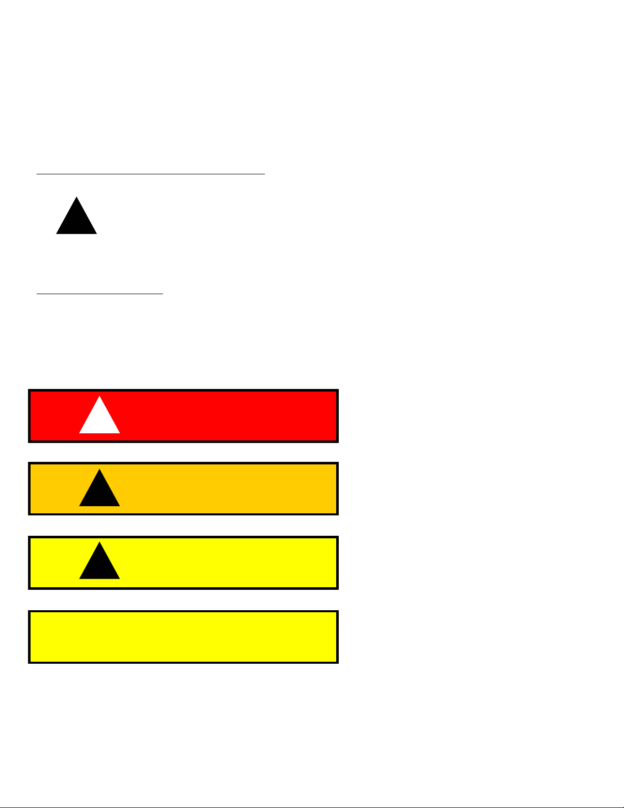
DANGER
!
WARNING
!
CAUTION
!
CAUTION
®
product.
Indicates an imminently hazardous
situation which, if not avoided, will
result in death or serious injury.
Indicates a potentially hazardous
situation which, if not avoided, could
result in death or serious injury.
Indicates a potentially hazardous
situation which, if not avoided, may
result in minor or moderate injury.
CAUTION used without the safety alert
symbol indicates a potentially hazardous
situation which, if not avoided, may
result in property damage.
October 15th, 2001 Help Line: 800-363-2488 4
Page 6
WARNING ELEMENTS (continued)
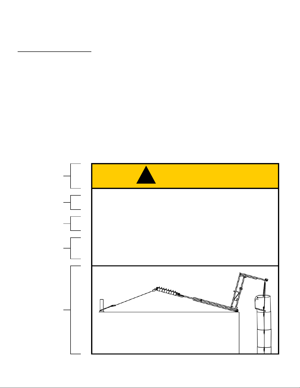
WARNING FORMAT
Warnings are usually displayed in a box to set them apart from other information. The box
consists of two or three panels, specifically:
• The signal word appears in the upper panel of the box.
• The hazard statement, consequence statement, and instruction statement(s) appear in the
lower panel of the box.
• In a warning that uses three panels, the third panel is pictorial, and identifies the hazard or
indicates how to avoid the hazard.
Here is an example of a Superchute
®
warning with three panels:
Signal word
with alert symbol
Hazard
Consequence
Instruction
Pictorial
(optional)
WARNING
!
• If the lifting device is overloaded it could fail and the
chute system could collapse.
• A falling chute system can seriously injure or kill.
• Do NOT overload the lifting device. Use the Forms and
Weight Charts of Section X to calculate the weight of
your chute system.
5 Help Line: 800-363-2488 October 15th, 2001
Page 7

3. IMPORTANT INFORMATION
• Planners, supervisors, installers and users of the chute system must be able
to refer to this manual at any time. Copies of this manual are available from
Superchute Ltd. free of charge, by mail or fax, and can be downloaded from
the Superchute® web site at: www.superchute.com
with the chute system on the job site, postpone installation and use of the
chute system until a manual is obtained.
• Before rigging or using the chute system, planners, supervisors, installers and
users should be familiar with applicable federal, state, and local safety
regulations.
• Use engineered rigging equipment to install and anchor chute sections (for
example, a Superchute® chute hoist).
. If this manual is not
• Do not replace original Superchute® parts with non-Superchute® parts.
• Do not mix Superchute® chute sections with chute sections of another brand.
• Superchute® equipment should only be used by workers who are fit to
operate it in a responsible manner.
• The Superchute
debris. Do not use as a permanent garbage or laundry chute, nor for any
other permanent application.
• This manual should not be taken as an overall survey on rigging technique,
fall protection, or structure appraisal. Whenever these considerations arise,
the planners, supervisors, installers and users of the chute system should
secure the services of trained professionals.
• A one-day training seminar is offered free of charge at the Superchute®
factory. The seminar examines the proper installation and use of
Superchute® chute sections and chute hoists. Call 1-800-363-2488 for
details.
system is designed to assist in the removal of construction
October 15th, 2001 Help Line: 800-363-2488 6
Page 8
4. CHUTE SECTIONS
Superchute
height. Two designs are available: Welded sections have a permanent tubular shape, while
Wraparound
removal solution.
®
chute sections are conical polyethylene tubes that measure 4 feet (1.2 meters) in
®
sections can be stored flat. Both designs provide an equally safe and easy debris
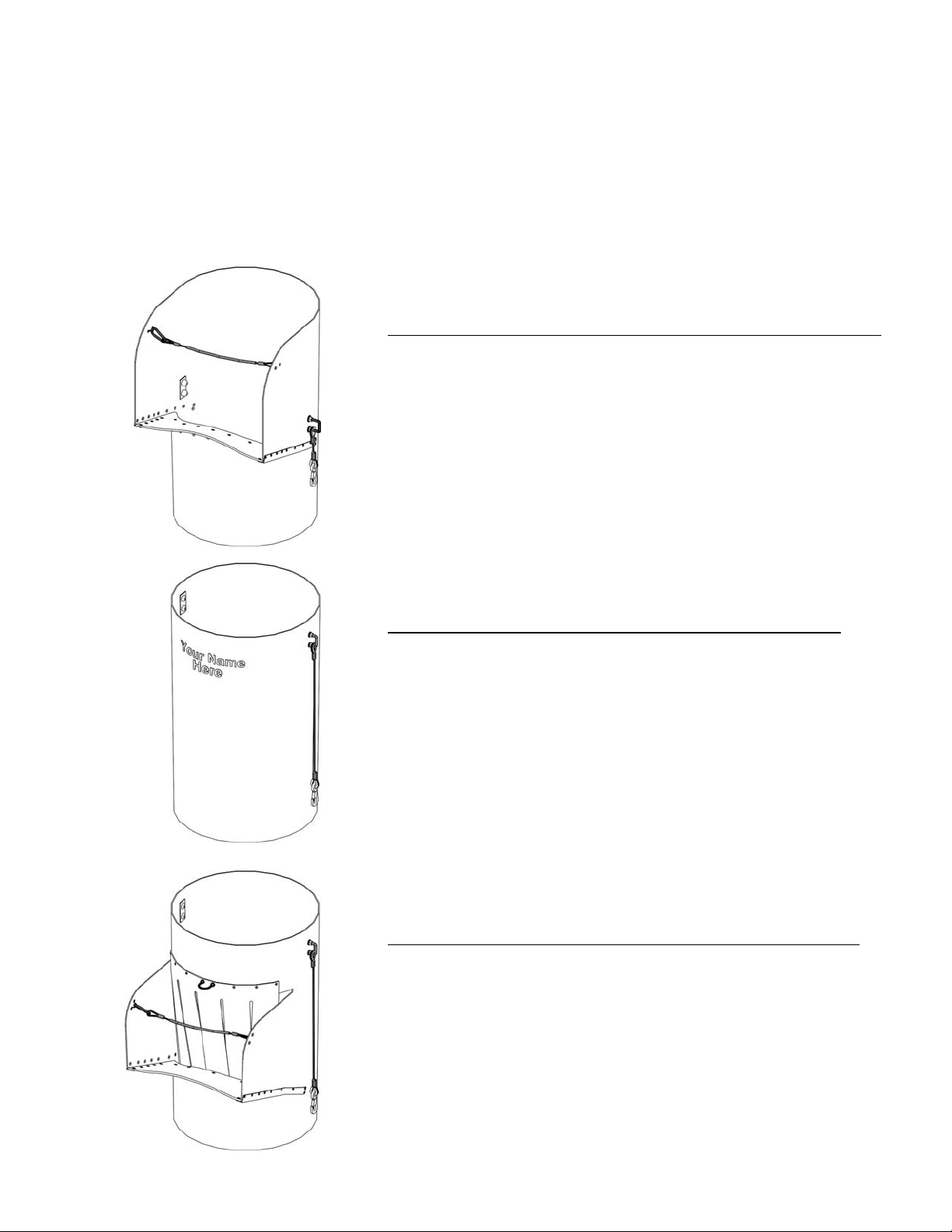
THE TOP HOPPER SECTION
• The Top Hopper is the uppermost section in a chute
• It is an entry point for debris
• Its scoop shape helps channel debris into the chute
• Must be used at the top of a chute
THE REGULAR SECTION
• The Regular Section is a tube
• A chute consists mainly of these sections
THE DOOR SECTION
• The Door Section is an entry point for debris
• It allows for debris removal from many levels
• A chute may contain many Door Sections
• The debris deflection curtain is replaceable
• Adjust the height using a Door Adjustment Kit
7 Help Line: 800-363-2488 October 15th, 2001
Page 9
5. THE CABLE ASSEMBLY
THE VITAL COMPONENT
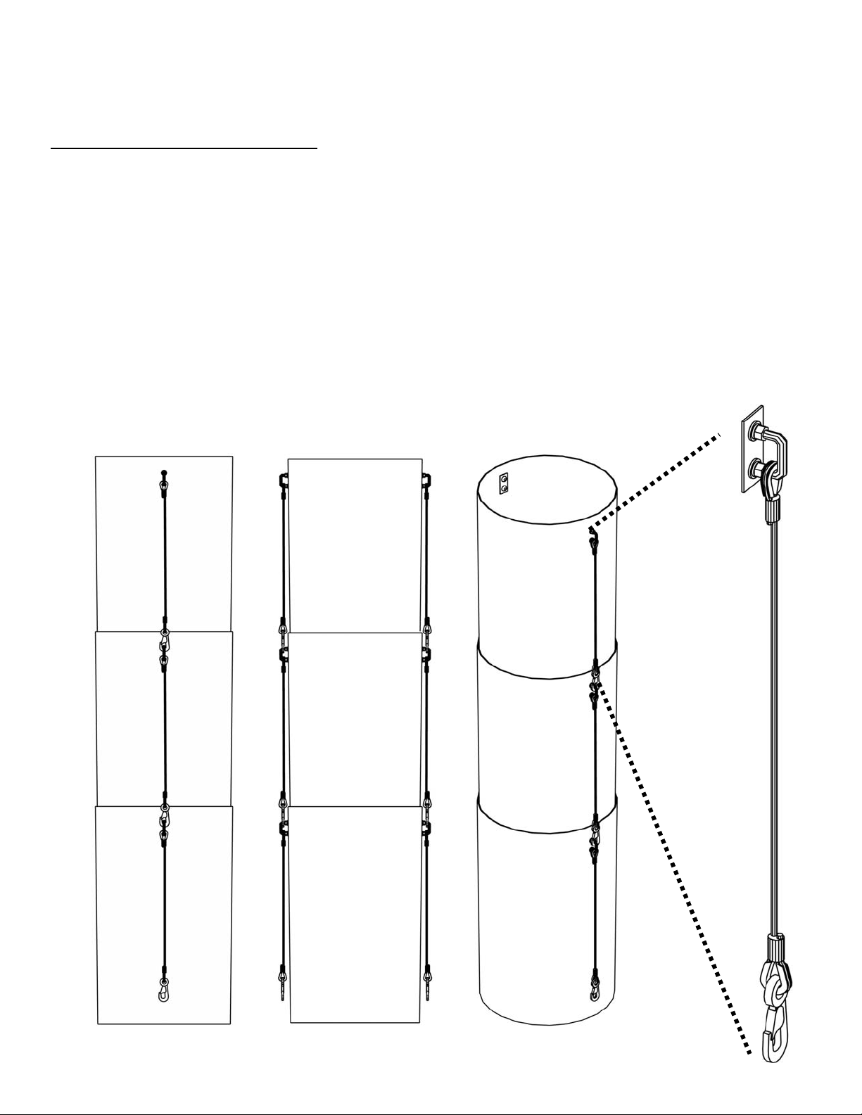
Every Superchute
are used to link one chute section to the next.
The cable assembly pair is the vital component of a chute section. Each pair supports the
weight of the chute sections beneath. Therefore, the uppermost pairs on a suspended chute
support more weight than cable assembly pairs located lower down on the chute.
Consequently, if your chute will mix Superchute
assemblies, plan to put the sections with the older cable assemblies at the base of the chute.
This action will put the stronger cable assemblies at the top of the chute, where they are most
needed.
Side View Front View Angled View
®
chute section is equipped with two strong, lightweight cable assemblies that
®
sections with older and newer cable
A
The cable assemblies
of chute section A
hold the weight of
chute sections B & C.
B
The cable assemblies
of chute section B
hold the weight of
chute section C.
C
Close-up view of
a cable assembly
October 15th, 2001 Help Line: 800-363-2488 8
Page 10
THE CABLE ASSEMBLY (continued)
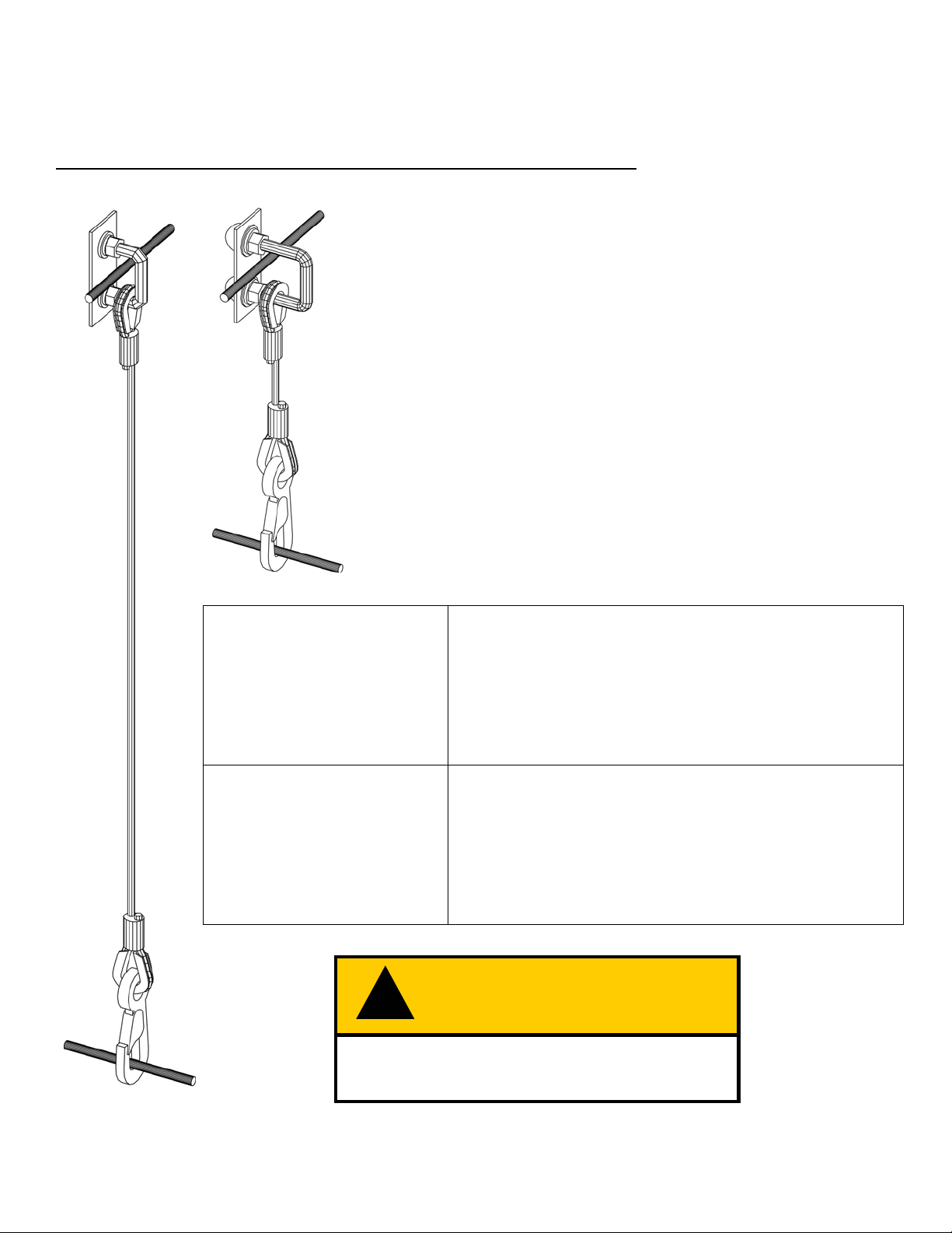
STRENGTH OF THE CURRENT CABLE ASSEMBLY
U-Bolt
New, undamaged cable assemblies that were manufactured
in February 1999 or later have the following specification*:
• The Breaking Strain of a cable assembly is 10,000 lb.
(4500 kg).
• The Working Load Limit of a cable assembly is 1000 lb.
Type 2 Type 1
(450 kg). The design factor is 10 to 1.
• Because there are two cable assemblies per chute section,
a chute section has a Working Load Limit of 2000 lb.
(900 kg).
Physical descriptions of the cable assembly types are
provided below:
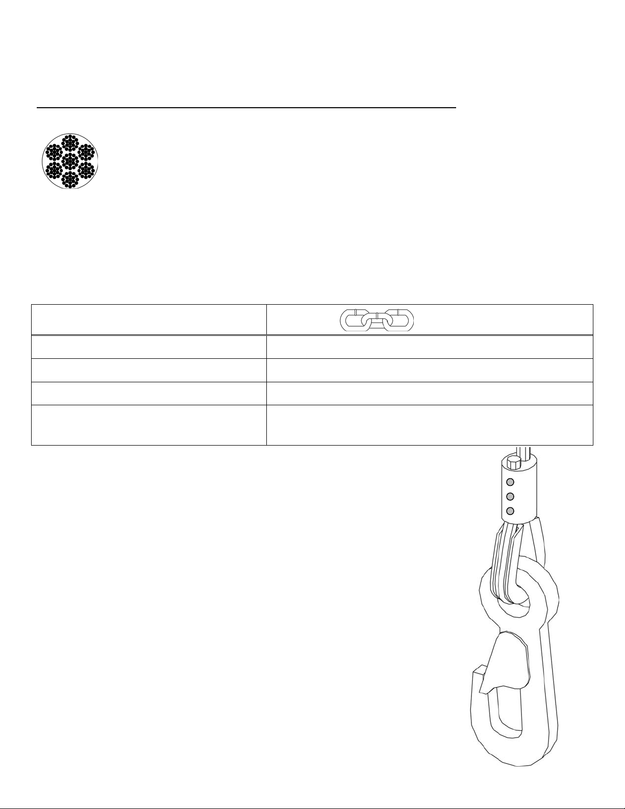
Wire
Rope
Type 1
For Regular and
Door Sections
• ½" (12.5 mm) diameter steel U-bolt
• Forged steel clip with gate
• 5/16" (8 mm) diameter galvanized wire rope
• Working length: 40” (102 cm) pin-to-pin (see sketch).
Î
Type 2
For Top Hopper
Sections
• 5/8” (15.5 mm) diameter steel U-bolt
• Forged steel clip with gate
• 5/16" (8 mm) diameter galvanized wire rope
• Working length: 16” (41 cm) pin-to-pin (see sketch).
Î
Clip
Measuring
Pin
* Height & weight limits for chute sections equipped with older cable assemblies are explained on the next page.
!
WARNING
Abuse or wear and tear will reduce the
strength of the cable assembly.
9 Help Line: 800-363-2488 October 15th, 2001
Page 11
THE CABLE ASSEMBLY (continued)
NEW HEIGHT & WEIGHT LIMITS OF CHUTE SECTIONS
Over time changes have been made to the cable assembly. As well, new height and weight
limits are in effect. Check the date stamp on every chute section to understand your new height
1
& weight limit:
a) If the chute section was manufactured in February 1999 or later, and is equipped with the original cable
assemblies, it can carry a maximum of 60 sections (200 feet, 60 meters) or 2000 lb. (900 kg) of chute,
whichever is reached first.2
b) If the chute section was manufactured between June 1996 and February 1999, and is equipped with the
original cable assemblies, it can carry a maximum of 30 sections (100 feet, 30 meters) or 1000 lb. (450 kg)
of chute, whichever is reached first.3 If you would like to be able to build a taller chute (up to the limits
described in “a)” above), contact the factory for retrofitting of the cable assemblies.
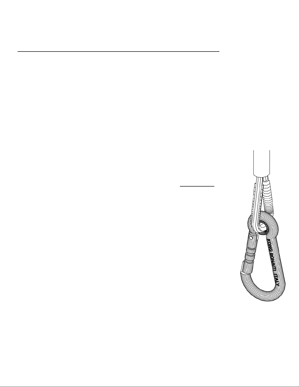
c) If the chute section was manufactured prior to June 1996, and is equipped with the
original cable assemblies, it can carry a maximum of 15 sections (50 feet, 15 meters) or
500 lb. (225 kg) of chute, whichever is reached first.4 The cable assemblies of these
sections feature lightweight, metal alloy clips stamped with the words “KONG –
BONAITI - ITALY” (shown on the right). The KONG clip is much weaker than the
forged ones currently used. The three possible colors of the KONG clip are:
If you have chute sections equipped with cable assemblies that use KONG clips, and
would like to be able to build a taller chute (up to the limits described in “a)” above),
contact the factory for retrofitting of the cable assemblies.
THE GATE OF THE “KONG” CLIP MUST CLOSE FULLY. If the gate is not fully
closed, its strength is greatly reduced. Oil the gate hinge and spring regularly. Discard
cable assemblies whose clip gates do not spring shut.
The above information applies to new, undamaged cable assemblies working
together in pairs. Abuse or wear and tear will reduce the strength of the cable
assembly. If you are unsure of the strength of your cable assemblies, please
call the Superchute
Notes:
1
As of June 1996 the month and year of manufacture have been branded into every chute section.
2, 3, 4
Superchute® makes 6 diameters of chute. The larger diameter chute sections weigh more, so they will
reach the weight limit before the height limit. Before each installation, calculate the precise weight of
your chute using the instructions and charts in Sections 7 and 8.
®
factory (800-363-2488).
1. blue frame with red gate
2. purple frame with blue gate
3. silver frame with silver gate
Gate
Frame
October 15th, 2001 Help Line: 800-363-2488 10
Page 12
THE CABLE ASSEMBLY (continued)
WHY IS WIRE ROPE USED IN THE CABLE ASSEMBLY?
"For general construction rigging never use a chain when it is
possible to use wire rope. The failure of a single link of chain can
result in a serious accident but wire rope on the other hand is
Cross sectional
view of a wire
rope
There are many advantages to wire rope:
frequently composed of 114 wires, all of which must fail before the
rope breaks. Wire rope gives you reserve strength and a chance to
notice a hazard, chains do not."
Rigging Manual, CSAO, 1996
Wire Rope Chain
Provides warning when worn No visible warning before failure
Consistent strength Inconsistent strength – except the high quality grades
Lightweight Heavy and bulky
The many strands create a multiple
point suspension system
Occasionally Superchute® will use chain in cases where adjustment is required. For
example: Door Adjustment Kits and chute hoists. However, only high quality Grade
70 and Grade 80 chains are ever used.
The three dots on the pressed sleeve
are Superchute’s
This mark has been in effect since
March 1998.
Close up view of the forged clip used
on cable assemblies since June 1996.
Single point suspension: Lose a link – lose it all.
Chain is only as strong as its weakest link.
®
identifying mark.
11 Help Line: 800-363-2488 October 15th, 2001
Page 13
THE CABLE ASSEMBLY (continued)
ATTACHMENT TO THE CHUTE WALL
Prior to installing a chute section, ensure that two cable assemblies are fastened securely to the
chute wall.
Please note that Wraparound
cable assemblies attached to the chute wall. This shipping method keeps the sections from
shifting in transport.
Attach cable assemblies to the chute wall using the instructions shown below and on the next
page (these instructions are included with every pair of packaged cable assemblies).
• A loosely attached U-Bolt could undo and cause the failure and
collapse of the chute.
• A falling chute system can cause serious injury and death.
• Attach each cable assembly to the chute wall, per the diagram
enclosed with every cable assembly bag (see next page).
• To further demonstrate the correct attachment, factory staff have
fitted the uppermost chute section in the crate with its cable
assemblies.
®
sections are usually shipped flat (from the factory), without the
WARNING
!
October 15th, 2001 Help Line: 800-363-2488 12
Page 14
THE CABLE ASSEMBLY (continued)
ATTACHMENT TO THE CHUTE WALL (continued)
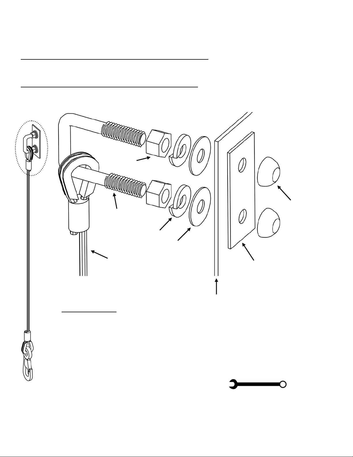
U-Bolt Installation Instructions
(EXTERIOR VIEW OF THE
Hex Nut
U-Bolt
Lock Washer
Washer
Wire Cable
INSTRUCTIONS:
1. Open the bag
2. Unravel the two cable assemblies – put one aside
3. Undo the 2 Dome Nuts
4. Remove the Backing Plate from the U-Bolt
5. Force U-Bolt through holes in the chute wall
6. Reach inside the chute to slip Backing Plate over the U-Bolt ends
7. Replace the 2 Dome Nuts – Hand tighten until flush with U-Bolts ends
8. Tighten the Hex Nuts using the supplied wrench
9. Repeat steps 3 to 8 with the second cable assembly
LEAVE CABLE ASSEMBLIES FASTENED TO THE CHUTE SECTION UNTIL THEY REQUIRE REPLACEMENT DUE TO WEAR & TEAR OR ABUSE
13 Help Line: 800-363-2488 October 15th, 2001
CHUTE)
(INTERIOR VIEW OF THE
CHUTE)
Dome Nut
Backing Plate
Chute Wall
Page 15
THE CABLE ASSEMBLY (continued)
MAINTENANCE
Check the condition of the cable assemblies on each chute section regularly:
• Replace cable assemblies that show signs of wear.
• Replace cable assemblies that have been strained.
• Oil the clip’s gate hinge and spring regularly. The gate must spring closed.
• For forged clips, spare gate springs can be purchased from Superchute
• Replace damaged cable assemblies with new, authentic Superchute
• Always change the full cable assembly, not just a part of it.
• Keep a written register, with dates and signatures, of all maintenance operations: record and
identify chute sections whose cable assemblies have been upgraded (or downgraded). Engrave a
code or date into the plastic chute wall adjacent the cable assembly, or attach a durable identifying
tag to the cable assembly.
Discard The Entire Cable Assembly If Any Of The Following Conditions Are Discovered:
THE WIRE ROPE:
• There are 3 or more protruding broken wires within a 2 inch (5 cm) interval.
• There are broken wires near attached fittings.
• The wire rope has kinks, birdcages, twists, or other distortions.
• The wire rope has been stretched.
• The wire rope is corroded.
• The wire has been damaged by heat, as evidenced by discolored wires.
2
1
®
Ltd.
®
cable assemblies.
THE CLIP:
• The gate is bent.
• The gate will not close.
• The frame is bent.
October 15th, 2001 Help Line: 800-363-2488 14
3
5
4
THE WIRE ROPE FITTINGS:
• The thimble is loose and rattles in cable eye.
• The pressed sleeve is cracked, loose, or damaged.
THE U-BOLT GROUP:
• The U-bolt is bent, cracked, or damaged. • Pieces are missing from the U-Bolt Group.
Page 16
THE CABLE ASSEMBLY (continued)
CAUTION!
Certain factors can be abusive and lessen the load that the cable assembly (and by extension, the
chute section) can withstand. Some examples are:
• twisting of the cable assembly
• disfigurement, deterioration by straining, usage, weathering, heat, and corrosion
• rapid application of load or jerking
• the application of excessive loads
Keep corrosive substances away from the cable assemblies, and do not weld near the chute
system.
Some types of damage may not be visible to the eye. Consider the following example:
Incident: A blockage occurred in a tall chute. The blockage went unnoticed and workers
continued to introduce debris into the chute. The installers had calculated the
weight of the unblocked chute to be 1500 lb. (680 kg).
Debris continued to accumulate in the chute until the blockage was finally
discovered by the inattentive safety monitor. A crane was called in and the
entire chute was lowered to the ground. The crane’s load indicator showed the
total weight of the chute and blocked debris to be 15,000 lb. (6800 kg).
Upon inspection of the cable assemblies, no obvious signs of strain were noted.
The chute sections were equipped with cable assembly pairs having a combined
working load limit of 2000 lb. (900 kg). The breaking strain of the cable
assembly pairs is 20,000 lb. (9000 kg).
Action: Although the cable assemblies showed no obvious sign of strain, the working
load limits were greatly exceeded. All the cable assemblies should be replaced.
Conclusion: If, during the course of your job, the working load limits of the cable assemblies
are accidentally exceeded, consult a structural engineer and the Superchute
factory to determine whether the chute sections in that system must be refitted
with new cable assemblies.
!
WARNING
®
15 Help Line: 800-363-2488 October 15th, 2001
Page 17
6. SELECT AN INSTALLATION AREA
Choose the installation area carefully. A poor choice can create a hazardous chute system.
Use the following guidelines when choosing the site for your chute installation.
1) SAFETY OF THE PUBLIC: The chute should be located in an area far from the public.
Always consider the consequences of a worst case scenario. For example:
• If the chute collapsed (due to a blockage that overloaded the cable assemblies)
would it fall across a high traffic area, over a road, over a pedestrian walkway?
• If a worker tossed a brick into a top hopper or door section, but missed, what could
be the consequence of the brick falling outside the chute?
• If a hole wore through the chute wall, and debris escaped from the chute, would the
debris shower the public below?
2) SHELTER FROM THE WIND:
• Select an area that provides shelter from the PREVAILING wind.
• Building corners that protrude outwards tend to accelerate the wind.
Due to this effect, do not place the chute within 20 feet (6 meters) of
a protruding building corner.
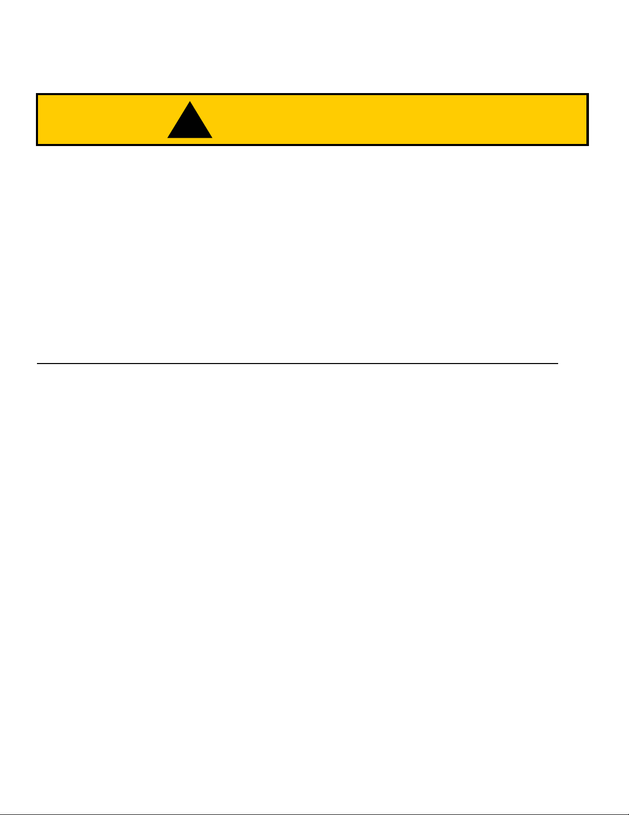
• Inset corners generally provide
excellent shelter from the wind.
Whenever possible, install the chute
in an inset corner (see sketch).
• The effect of wind on the chute is
discussed in Section 10: Installation,
under the heading: “Wind &
Restraint Issues”.
A chute shown installed in an inset corner
Note the protruding corners (circled)
October 15th, 2001 Help Line: 800-363-2488 16
Page 18
(
)
SELECT AN INSTALLATION AREA
(continued)
3) ELECTROCUTION: Prevent electrocution by choosing an area that is free of electric
cables. If cables are present, contact your local electrical authority before proceeding.
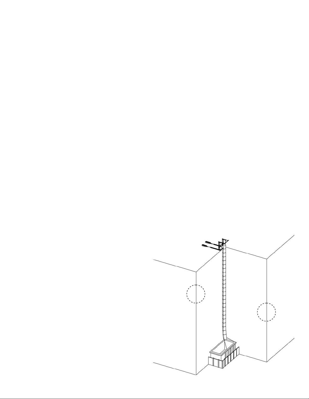
4) THE CHUTE MUST HANG VERTICALLY: To reduce the risk of a blockage, choose an
area where the chute will hang vertically. Horizontal displacement of the chute must not
exceed 20% of the chute’s height. See the sketch below.
If the chute does not hang vertically,
debris will rub against the chute wall.
This friction will cause the speed of the
moving debris to decrease, possibly to
the point where debris stops moving,
thereby creating a blockage.
50 ft
(15 m)
10 ft
3 m
5) PROTRUSIONS THAT CONSTRICT THE CHUTE: Choose an area that will not force
the chute to bend over balconies, ledges or any other kind of large structural protrusion that
will constrict the chute. The next page provides further information on this subject.
Right
50 ft x 20% = 10 ft
15 m x 20% = 3 m
17 Help Line: 800-363-2488 October 15th, 2001
Page 19

SELECT AN INSTALLATION AREA
(continued)
BLOCKAGE HAZARDS
• If the chute is not hung vertically, there will be a bend in it.
• If the bend is too sharp, when users introduce debris they will clog the chute. If
the blockage is not noticed and more debris is introduced, the total weight of the
chute will rapidly increase, and the chute system could collapse.
• A collapsing chute system can cause serious injury and death.
• Do not create a blockage hazard:
!
1. Choose a location that will allow the chute to hang vertically.
2. Choose a location that will not crimp or constrict the chute.
WARNING
CONSTRICTION
POINTS!
Right Wrong Wrong
October 15th, 2001 Help Line: 800-363-2488 18
Page 20

SELECT AN INSTALLATION AREA
(continued)
SPECIAL CASES
In cases where the building exterior is stepped or irregular, consider the following options:
1. Can the chute be installed in an unused elevator shaft, inside the building?
This option is usually feasible on new construction projects.
2. Can the chute be split into two or more vertical lengths? See the sketch below for
clarification.
Twin Containment Areas.
Empty one while the other fills.
19 Help Line: 800-363-2488 October 15th, 2001
Page 21

7. ASSESS CHUTE HEIGHT & WEIGHT
9
.
• The first step in undertaking a chute installation is to formulate an installation plan.
• This page is a planning tool, which is used here to illustrate an imaginary chute job.
• The next page is clean and is for your own use. Photocopy it and use it to plan your chute installations.
JOB NAME: __________________________ Measurements: Imperial or Metric?
1. What is the anticipated height of the chute? ________ feet or meters.
Measure or calculate the drop that your chute will cover.
2. How many chute sections will be needed?
Height in feet x 3 ÷ 10 = ________ sections needed.
When linked, 3 chute sections of any type will create a 10 foot drop.
or
Height in metres = ________ sections needed.
When linked, a chute section of any type creates a 1 meter drop.
3. How many entry sections will be needed? ________ sections.
Many chutes are designed with a Top opening only. However, you may want to use Door
sections if you will be working on several floors simultaneously.
4. What diameter of chute will be used? Circle:
Every chute section is branded with its diameter.
5. Calculate the total weight of the chute using the form below:
Every chute section is branded with its weight.
Section Weights are also provided on pages 22, 23.
Hotel On First Ave.
70 feet
70 feet x 3 divided by 10 = 21
21
3
[18"] [23"] [27"] [30"] [33"] [36"]
Chute Weight Calculation Form
Quantity Weight in lb. or kg. Weight in lb. or kg.
A) ______ Top Hopper x ______ each = ________________
B) ______ Door Sections x ______ each = ________________
C) ______ Regular Sections x ______ each = ________________
D) ______ Steel Liners x ______ each = ________________
1
Wraparound
2
Wraparound
18
Wraparound — 3/16” wall
2
41 lb.
50 lb.
39 lb.
40 lb.
SAMPLE
41 lb.
100 lb.
702 lb.
80 lb.
A+B+C+ D = TOTAL WEIGHT OF THE CHUTE = ________________
October 15th, 2001 Help Line: 800-363-2488 20
23 lb
Page 22

ASSESS CHUTE HEIGHT & WEIGHT (continued)
Before the chute is rigged it’s height and weight must be calculated. Photocopy this form and use it with the
weight charts provided on the next two pages. Knowing the total weight of the chute allows the installer(s) to
choose an appropriate lifting device and suitable anchors. If at any time you would like to discuss the
particulars of your job situation, please feel free to call the Superchute® factory: 1-800-363-2488.
JOB NAME: __________________________ Measurements: Imperial or Metric?
1. What is the anticipated height of the chute? ________ feet or meters.
Measure or calculate the drop that your chute will cover.
2. How many chute sections will be needed?
Height in feet x 3 ÷ 10 = ________ sections needed.
When linked, 3 chute sections of any type will create a 10 foot drop.
or
Height in metres = ________ sections needed.
When linked, a chute section of any type creates a 1 meter drop.
3. How many entry sections will be needed? ________ sections.
Many chutes are designed with a Top opening only. However, you may want to use Door
sections if you will be working on several floors simultaneously.
4. What diameter of chute will be used? Circle:
Every chute section is branded with its diameter.
5. Calculate the total weight of the chute using the form below:
Every chute section is branded with its weight.
Section Weights are also provided on pages 22, 23.
[18"] [23"] [27"] [30"] [33"] [36"]
Chute Weight Calculation Form
Quantity Weight in lb. or kg. Weight in lb. or kg.
A) ______ Top Hopper x ______ each = ________________
1
B) ______ Door Sections x ______ each = ________________
C) ______ Regular Sections x ______ each = ________________
D) ______ Steel Liners x ______ each = ________________
A+B+C+ D = TOTAL WEIGHT OF THE CHUTE = ________________
21 Help Line: 800-363-2488 October 15th, 2001
Page 23

8. CHUTE SECTION WEIGHT CHARTS
IMPERIAL WEIGHTS
THE WEIGHTS ON THIS PAGE ARE GIVEN IN POUNDS (LB).
• For metric weights, see the next page.
• An “X” signifies that no such section exists.
• If using steel liners, do not forget to account for their weight.
WELDED SECTION WEIGHTS (in lb.)
Diameter Wall Thickness Regular Top Hopper Door
18” 3/16” (5 mm)
23” 3/16” (5 mm)
27” 3/16” (5 mm)
30” 3/16” (5 mm)
30” 5/32” (4 mm)
30” 1/8” (3.2 mm)
33” 3/16” (5 mm)
36” 3/16” (5 mm)
WRAPAROUND® SECTION WEIGHTS (in lb.)
23 24 29
27 29 36
32 34 41
36 39 47
27 X X
X X X
X 40 50
X 46 57
Diameter Wall Thickness Regular Top Hopper Door
18” 3/16” (5 mm)
23” 3/16” (5 mm)
27” 3/16” (5 mm)
30” 3/16” (5 mm)
30” 5/32” (4 mm)
30” 1/8” (3.2 mm)
33” 3/16” (5 mm)
36” 3/16” (5 mm)
X X X
30 30 40
34 41 47
39 41 50
31 X X
28 X X
43 48 57
46 55 64
LINER WEIGHTS (in lb.)
For 18” dia. For 23” dia. For 27” dia. For 30” dia. For 33” dia. For 36” dia.
23 lb. 32 lb. 37 lb. 40 lb. 48 lb. 53 lb.
October 15th, 2001 Help Line: 800-363-2488 22
Page 24

WEIGHT CHARTS (continued)
METRIC WEIGHTS
THE WEIGHTS ON THIS PAGE ARE GIVEN IN KILOGRAMS (KG).
• For imperial weights, see the previous page.
• An “X” signifies that no such section exists.
• If using steel liners, do not forget to account for their weight.
WELDED SECTION WEIGHTS (in kg.)
Diameter Wall Thickness Regular Top Hopper Door
46 cm (18”) 5 mm
58 cm (23”) 5 mm
69 cm (27”) 5 mm
76 cm (30”) 5 mm
76 cm (30”) 4 mm
76 cm (30”) 3.2 mm
84 cm (33”) 5 mm
91 cm (36”) 5 mm
WRAPAROUND® SECTION WEIGHTS (in kg.)
10.5 11.0 13.0
12.5 13.0 16.5
14.5 15.5 19.0
16.5 18.0 21.5
12.5 X X
X X X
X 18.0 23.0
X 21.0 26.0
Diameter Wall Thickness Regular Top Hopper Door
46 cm (18”) 5 mm
58 cm (23”) 5 mm
69 cm (27”) 5 mm
76 cm (30”) 5 mm
76 cm (30”) 4 mm
76 cm (30”) 3.2 mm
84 cm (33”) 5 mm
91 cm (36”) 5 mm
X X X
14.0 14.0 18.0
15.5 19.0 21.5
18.0 19.0 23.0
14.0 X X
13.0 X X
19.5 22.0 26.0
21.0 25.0 29.0
LINER WEIGHTS (in kg.)
For 18” dia. For 23” dia. For 27” dia. For 30” dia. For 33” dia. For 36” dia.
10.5 kg. 14.5 kg. 17.0 kg. 18.0 kg. 22.0 kg. 24.0 kg.
23 Help Line: 800-363-2488 October 15th, 2001
Page 25

9. ON THE SITE
eet
PREPARATION OF WELDED STYLE SECTIONS FOR USE
Welded style sections are permanent tubes. Sketches are shown below. No assembly of this
section style is needed, providing the cable assemblies are properly attached.
Occasionally, Welded style regular sections that have been stacked for storage or transport can
get stuck together. To get them apart, lie the bundle on its side and have two people “row” the
chute sections apart.
Top Hopper Section Regular Section Door Section
Push with f
If this technique does not work, use a winch to pull the sections apart.
If all of the sections you will be using are of the Welded style, then please proceed to page 29.
October 15th, 2001 Help Line: 800-363-2488 24
Pull with hands
Page 26

ON THE SITE (continued)
PREPARATION OF WRAPAROUND® STYLE SECTIONS FOR USE
Wraparound
If all of the sections you will be using are of the Welded style, then please proceed to page 29.
Assembly Time:
The following three pages show the assembly procedure.
®
style sections have the ability to go flat for storage and job-to-job shipping.
• The assembly of a Regular section requires approximately 1 minute.
• The assembly of a Door or Top Hopper section requires approx. 10 minutes.
25 Help Line: 800-363-2488 October 15th, 2001
Page 27

ON THE SITE (continued)
ASSEMBLY OF THE WRAPAROUND® TOP HOPPER SECTION
Heavy Duty
Aluminum
Kickboard Edge
Heavy Duty
Aluminum
Clasp
Your Name
Here
Polyethylene
Plastic Wall
Thickness: 3/16” (5 mm)
TO USE:
Flat: Ready for Transport / Storage
1. Lay down section with U-bolts facing the ground
2. Wrap the aluminum clasp edges together
3. Fasten clasp with carriage bolts & wrench (supplied)
4. Attach kickboard with hexhead bolts & wrench (supplied)
Polyethylene Kickboard
Thickness: 3/8” (9 mm)
Assembled:
Ready for Use
October 15th, 2001 Help Line: 800-363-2488 26
Page 28

ON THE SITE (continued)
ASSEMBLY OF THE WRAPAROUND® REGULAR SECTION
Heavy Duty
Aluminum
Flat Bar
(on each side)
Flat: Ready for Transport / Storage
TO USE:
Your Name
Here
Saf ety
ice
Not
Your Name
Here
Polyethylene Plastic Wall
Thickness (inches): 1/8”, or 5/32”, or 3/16”
Thickness (metric): 3.2 mm, or 4 mm, or 5 mm
Red Rope
Eyebolts
(store on clips)
1. Remove 5 eyebolts from the cable assembly clip
2. Lay down section with U-bolts facing the ground
3. Wrap the ends of the section together
4. Align and mate the 5 studs with the 5 holes
5. Insert 5 supplied eyebolts into studs. Hand tighten
6. Pass the red elastic rope through all 5 eyebolts
7. Tie the elastic to the lowest eyebolt
8. With the elastic in place the eyebolts cannot vibrate out
Assembled: Ready for Use
27 Help Line: 800-363-2488 October 15th, 2001
Page 29

ON THE SITE (continued)
ASSEMBLY OF THE WRAPAROUND® DOOR SECTION
Your Name
Here
Heavy Duty
Aluminum
Clasp
Polyethylene
Plastic Wall
3/16” (5 mm)
Thickness:
Flat: Ready for Transport / Storage
TO USE:
1. Lay down section with U-bolts facing the ground
2. Wrap the aluminum clasp edges together
3. Fasten clasp with carriage bolts & wrench (supplied)
4. Attach kickboard with hexhead bolts & wrench (supplied)
Polyethylene Kickboard
Thickness: 3/8” (9 mm)
Assembled: Ready for Use
Heavy Duty Aluminum
Kickboard Edge
October 15th, 2001 Help Line: 800-363-2488 28
Page 30

10. INSTALLATION
CHUTE HOISTS
Safer chute installations can be achieved using engineered Superchute
Superchute® hoists are designed specifically for RAISING, ANCHORING, & LOWERING the
chute. Eleven models of hoist are available. The model name of a hoist refers to the max. weight
it can manage in pounds, for example: the SC-500-bd can raise, anchor, & lower 500 lb. (225 kg).
Bolt Down Frames*
For Concrete Slabs
model SC-250-bd
model SC-500-bd
model SC-750-bd
Loadspreaders
For Windows
model SC-350-w
model SC-600-w
®
chute hoists.
Roofer Hoists*
model SC-300-cb
model SC-605-cb
model SC-905-cb
• assemble in 10 minutes with locking pins
• easy to transport & install
• only to be used for lifting chute sections
• galvanized steel construction
Hoisters* for Flat Decks
model SC-610-cb
model SC-900-cb
model SC-2000-cb
• The support frames feature a design factor of 3:1
• all use a removable Fishpole
• all designs work with cranes
• a “*” indicates a patented design U.S. Pat. 5,934,437
29 Help Line: 800-363-2488 October 15th, 2001
Page 31

INSTALLATION (continued)
CHECK THE CONDITION OF THE COMPONENTS
Every time the chute is to be rigged or used, make sure the following items are in good
condition: Superchute
Superchute
equipment, such as Door Adjustment Kits and Tie-Back Kits. Thorough overhaul servicing is
available from Superchute
®
chute sections, Superchute® steel liners, and any other ancillary Superchute®
THE TWO INSTALLATION STEPS
The installation of a chute consists of two steps:
The following pages explain how to best accomplish these tasks.
®
hoist(s), Superchute® spreader bar, Superchute® cable assemblies,
®
Ltd.
Step 1: Raise the chute sections
Step 2: Anchor the chute sections
RAISE THE CHUTE SECTIONS
A chute can be raised using various devices. Although the sketches on the following pages
show a Superchute
lifts, may be appropriate as long as they can safely manage the chute load.
Respect the weight limitations of your lifting device – an accident may result if you attempt to
lift beyond your capacity.
All lifting devices require the procedure shown on the following pages.
October 15th, 2001 Help Line: 800-363-2488 30
®
Hoist in use, other lifting devices, such as cranes, material hoists, or boom
Page 32

INSTALLATION (continued)
Attach a Spreader Bar to the hoisting cable. Superchute
meet your needs: the Light Duty spreader bar, and the Heavy Duty spreader bar.
The Light Duty spreader bar has cables and features a working load limit of 1000 lb. (450 kg).
The Heavy Duty spreader bar has chains and features a working load limit of 2000 lb. (900 kg).
®
manufactures two spreader bars to
The Light Duty spreader bar
has cables, and a working load limit
(WLL) of 1000 lb. (450 kg).
The Heavy Duty spreader bar has
chains, and a working load limit
(WLL) of 2000 lb. (900 kg).
31 Help Line: 800-363-2488 October 15th, 2001
Page 33

INSTALLATION (continued)
WARNING
GROUND WORKERS MUST WEAR HARDHATS
• Cable assemblies could be strained and
• As well the chute could dig into the
• Do not assemble the chute on the
!
WARNING
!
damaged if the chute is first assembled
completely on the ground and then
hauled into the air.
ground and act like an anchor, which
could cause the lifting device to topple.
ground. Use the method shown on the
following pages.
The lifting device used in this
installation is a Superchute
Bolt-Down Frame.
®
• Attach a chute section
to the Spreader Bar.
GROUND
October 15th, 2001 Help Line: 800-363-2488 32
Page 34

INSTALLATION (continued)
Communication:
Ground-level workers and hoist level-workers
• Raise the section 4 feet.
(1.2 meter)
should use 2-way radios (walkie-talkies) to
communicate with each other.
4 feet
• Position another section
beneath the upper
section.
33 Help Line: 800-363-2488 October 15th, 2001
Page 35

INSTALLATION (continued)
• Lower the suspended section into the
• Connect the two sections with the upper
As you link Regular sections together, arrange them so
that the plastic weld or Wraparound
from side to side, as depicted in the sketch on the right.
Alternating the clasps will help the chute hang straight.
®
clasp alternates
section beneath it.
section’s cable assemblies.
Align chute sections
so that seams alternate
from left to right.
WARNING
!
Do NOT place hands between
chute sections.
October 15th, 2001 Help Line: 800-363-2488 34
Page 36

INSTALLATION (continued)
1
!
• If the chute were to become snagged on the building
face during the lifting operation, the lifting device and
cable assemblies could become overloaded.
• The overload could lead to a collapse of the chute
system. A collapsing chute system can seriously injure
or kill.
• As the chute is raised, have a spotter make sure the
chute does not become snagged on the building face.
WARNING
1. Raise the chute length.
2. Position another section below the suspended
chute.
3. Lower the suspended chute length into the
A
B
section.
4. Connect clip of cable assembly (A) to U-bolt (B).
5. Repeat with the cable assembly on opposite side.
3
6. Raise the chute length.
2
35 Help Line: 800-363-2488 October 15th, 2001
Page 37

INSTALLATION (cont’d)
• Repeat the instructions on the prior page
until the Top Hopper section arrives at
the hoist level.
The lifting device used in this
installation is a Superchute
Bolt-Down Frame.
!
• If the lifting device is overloaded it could fail and the
chute system could collapse.
• A falling chute system can seriously injure or kill.
WARNING
®
• Do NOT overload the lifting device. Use the Forms and
Weight Charts of Sections 7 and 8
weight of your chute system.
October 15th, 2001 Help Line: 800-363-2488 36
to calculate the
Page 38

INSTALLATION (continued)
ANCHOR THE CHUTE SECTIONS
Superchute
using your own method, please be advised of the following guidelines:
®
chute hoists can be used to safely anchor a chute. If you wish to anchor your chute
• A sufficiently strong anchorage must be present in order to anchor
the chute to the building. At the window, roof, or floor slab level,
locate structural members of the building that are strong enough to
anchor your chute.
• The anchors must be able to support at least three times the weight of
the chute.
• A structural engineer must verify the adequacy of the anchors and
supporting structure.
• Use rated rope to anchor the chute. 5/8” (16 mm) diameter nylon
rope, rated to 10,000 lbs. (4500 kg), works well for this task.
• Use recognized safety knots, such as the bowline or the figure eight,
for all rope work.
• Anchor the chute to structural members of the building according to
instructions provided in the sub-section: Wind & Restraint Issues.
In the sketch above, two “piggybacked” Bolt-Down Frames are used to anchor the chute.
Superchute
Don’t take chances. Use Superchute
®
hoists are simple to use, effective, and above all, engineered for safety.
®
hoists!
37 Help Line: 800-363-2488 October 15th, 2001
Page 39

INSTALLATION (continued)
USING A SCAFFOLD, STAGE, OR PLATFORM AS AN ANCHOR
• If a scaffold, suspended stage, platform or similar structure is
used to support the chute, and a blockage occurs in the chute,
the additional weight could cause the structure to topple or fail.
• The collapse of the support structure and chute could cause
serious injury or death.
• The support structure must be capable of holding at least five
times the weight of the chute, in addition to being able to hold the
weight of men, machinery, and materials with an adequate safety
factor.
• A structural engineer must verify the adequacy of the support
structure.
Additional Guidelines For Chutes Anchored To Scaffolds:
• The scaffold should be installed by professional scaffold
erectors.
!
WARNING
• The scaffold should be erected and tied in accordance with
government regulations and manufacturer’s instructions or
as designed by an engineer.
• The chute must be restrained to the scaffold at intervals of
less than 25 feet (8 meters), in order to prevent wind sway.
The sketch on the left shows the chute installed inside
the scaffold. This arrangement is best as it distributes
the weight of the chute evenly on the scaffold.
October 15th, 2001 Help Line: 800-363-2488 38
Page 40

INSTALLATION (continued)
WIND & RESTRAINT ISSUES
Because a chute installation may remain in place for days, weeks, or months, the installers must
consider how the chute will be affected by winds. Installers should also expect that strong winds
could arrive at times when there are no supervisors or workers on the job (ie: overnight or on the
weekend).
The way in which the chute will react to winds depends on how it was restrained, and the spacing
interval between restraints.
The installer can use either taut
restraints. The following two pages explain this concept further.
But first, take a look at the sketch below. It shows the potential effect of using the wrong type of
restraint. Why is the hoist pulled over? Note the hoist tie-backs, and their help in this instance.
Hoister
60 ft.
(18 m)
W
restraints or slack restraints based on the spacing between
WRONG
• The hoist is about to fail because
the chute installers did not
restrain the chute properly.
• The chute is acting like a sail
under tension.
• The proper way to restrain a
chute is shown on the next 2
pages.
Taut restraints
39 Help Line: 800-363-2488 October 15th, 2001
Page 41

INSTALLATION (continued)
TAUT RESTRAINTS
If the installer can access the entire length of the chute, use taut restraints. If the chute is
anchored to a scaffold, use taut restraints. Secure the chute tightly to the building structure, at
intervals of 25 feet (8 meters) or less, using a 5/8” (16 mm) diameter nylon rope or equivalent.
As the sketches show, the closely spaced restraints hold the chute tight to the building structure,
preventing the wind from moving the chute.
13 ft.
(4 m)
NO WIND WIND
• Spacing less than 25 ft. (8 m)
• Use TAUT restraints
• Because the interval between
restraints is less than 25 feet
(8 m) the wind does not affect
the chute.
W
Restraints
The sketches on this page show the correct application of restraints.
October 15th, 2001 Help Line: 800-363-2488 40
Page 42

INSTALLATION (continued)
SLACK RESTRAINTS
If the restraint intervals will be more than 25 feet (8 m), use slack restraints to secure the chute
to the building structure. Slack restraints keep the chute from acting like a taut sail by allowing
it the freedom to form an arc and move up and down. Do not mix slack and taut restraints.
The attachment of the chute’s discharge end to the container (or other anchor) must be
considered a restraint. Use Container Cord. Do not tie it tightly as the chute must be able to
move if heavy winds arise.
If the wind strengthens, the strain could cause the Superchute
beneficial, as the chute will be released and failure of the hoist will be avoided.
NO WIND WIND
35 ft.
(11 m)
• Spacing greater than 25 ft. (8 m)
• Use SLACK restraints.
®
Container Cord to fail, which is
• When subjected to wind, the
chute is able to move freely.
• The restraints allow the
chute to rise.
• Additional downward forces
are not exerted on the hoist.
• In this case, the Container
W
45 ft.
(14 m)
Cord was tied to the lamp
pole to provide more slack
for chute movement.
The sketches on this page show the correct application of restraints.
41 Help Line: 800-363-2488 October 15th, 2001
Page 43

INSTALLATION (continued)
USING LOAD CELLS TO DETECT A BLOCKAGE
If load cells are installed at the top of the chute, users will be able to monitor the
weight of the chute. An increase in the weight of the chute indicates that a
blockage has occurred. For further information on load cells and their use in a
chute system, please contact Superchute
Close up view of a load cell kit.
A pair of load cells
®
Ltd.
Shown on a Hoister
October 15th, 2001 Help Line: 800-363-2488 42
Page 44

INSTALLATION (continued)
USE A SAFETY ROPE
If a major problem arises and the chute collapses, it could fall away from the
building the way a tree falls when cut at the trunk. Prevent a chute from
falling this way by using a Safety Rope.
In the event of a collapse, a chute equipped with a Safety Rope is forced to fall
the length of the rope, thus keeping it close to the building.
Follow this procedure when installing a Safety Rope:
1. Secure the rope to a 5000 lb. (2250 kg) capacity anchor above the
anticipated height of the chute system. Do not secure the rope to a chute
hoist or to an anchor that is used or will be used for any other application.
If the rope must lie across a working floor, then consider using wire rope as
it will better resist people treading on it.
2. Lower the end of the rope to the ground.
3. Pass the rope through several clips (the number of clips will depend on the
length of the chute).
4. As the chute is raised and added to, attach a clip to the U-bolt of every third
chute section.
5. The clips will slide up the rope, rising with the chute sections to which they
were attached.
6. Tie the rope snugly and securely to the last chute section.
(Coil any unused rope on the side).
7. If the chute collapses, it will fall along the rope.
Superchute® Ltd. sells
Safety Rope Kits
43 Help Line: 800-363-2488 October 15th, 2001
Page 45

INSTALLATION (continued)
DAMAGE PREVENTION AND STEEL LINERS
Prevent damage to the chute by keeping the chute hanging straight.
Install Superchute
Hopper, the Door, and any part of the chute where there is a slight curve in the chute.
Note: Installed liners add considerable weight to the chute (see Section 8 for individual liner
weights).
®
steel liners in damage-susceptible areas of the chute, such as the Top
Steel Liner installed in a Regular chute section
October 15th, 2001 Help Line: 800-363-2488 44
Page 46

INSTALLATION (continued)
THE CONTAINER
• The debris exiting the chute will be directed into a suitable steel container. A dump-truck, or
similar loading vehicle, is not suitable because falling material can present a hazard to the
truck operator.
• Barricade the container area (see page 47 for details).
• Tie the chute’s discharge end to the container using one or two lengths of Superchute®
Container Cord (provided free of charge with every chute order). Unlike Regular cords and
ropes, Container Cord is designed to fail. If a full container is accidentally driven away
with the chute still attached, the Container Cord will fail and the chute system will not be
pulled from the building.
• Do not double up the Container Cord or use more than one or two lengths to attach the
chute’s discharge end to the container. The effect would be to increase the strength of the
attachment, which would make it less likely to fail if it should need to do so. See the
sketches below.
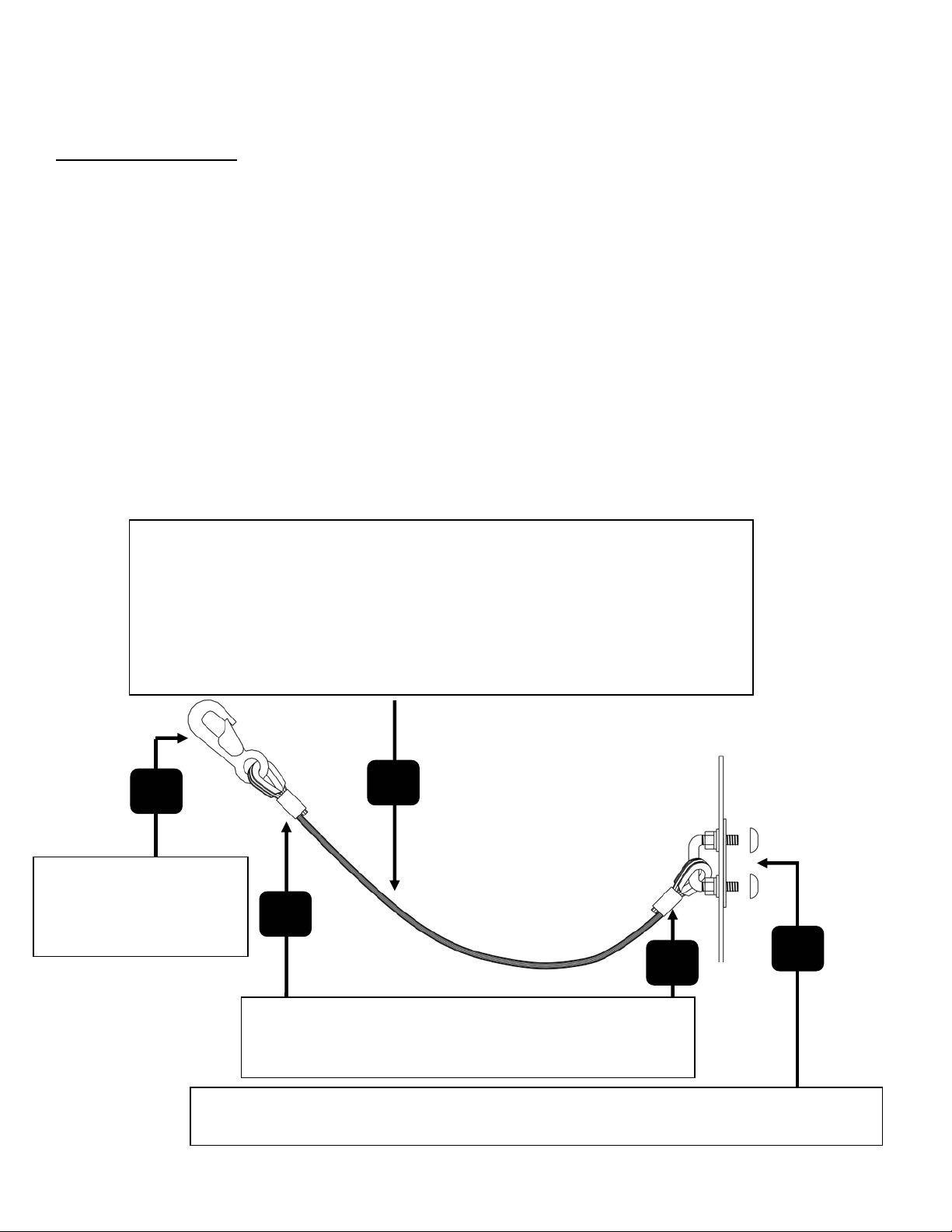
Å RIGHT
The chute is tied off to the far end of the
container. This arrangement allows the end of
the chute to be easily moved about the
container, and provides a desirable level of slack
for any strong winds.
WRONG Æ
The Container Cord has been applied in such a way
that it will not fail easily if undue stress is applied
.
45 Help Line: 800-363-2488 October 15th, 2001
Page 47

INSTALLATION (continued)
FIRE PREVENTION
To prevent a container from catching fire and subsequently setting fire to the building and/or the
suspended chute (which could also introduce smoke into the building), users and installers must
take all of the following precautions:
1. Keep the contents of the trash container wet at all times (the Superchute
Drencher is available for this purpose). Water application will also help control dust. Do
not apply water if the temperature drops below the freezing point, or if the container
contains hazardous debris (the runoff could be toxic).
2. Make provisions for water
application on all floors
with exposure to the chute.
3. Install the container at least
10 feet (3 meters) away
from the building (check
local by-laws).
4. Seal the container with a
fireproof lid (example:
metal sheets) at the end of
each workday.
5. Move the base of the chute 10 feet (3 meters) away from the container at the end of each
work day, or, disconnect the last 10 feet (3 meters) of chute at the end of each work day.
6. Post clear signs around the trash container and on all floors facing the chute. Indicate:
Superchute®
Container Drencher
®
Container
!
WARNING
No Smoking, No Open Flame, No Welding, No Ignition Source
Within 20 Feet (6 Meters) Of The Chute And Trash Container.
Do Not Introduce Any Flammables.
Keep Container Contents Wet. Apply Water Frequently.
October 15th, 2001 Help Line: 800-363-2488 46
Page 48

11. USAGE INSTRUCTIONS
GENERAL INSTRUCTIONS
Failure to adhere to these instructions could result in injury and/or death.
• Barricade the container area in order to protect
workmen and the public from any material that may
ricochet out of the container. Build the barricade
using plywood sheets, screens or similar materials.
In the event that debris is accidentally thrown into
the chute when the discharge end of the chute is not
directed into the container, or the container has been
removed, the barricaded area may help to prevent
injury.
• Do not introduce concrete blocks, spikes, flammables, or toxic dusts. Do not drop more than
50 lb. (23 kg) of debris at a time into chute. Do not use motorized loaders to introduce
debris into the chute (motorized loaders introduce too much debris, too quickly).
• Never stand under, or look up the discharge end of a chute.
• Never look into, or place body parts into the opening of a Door section.
®
• All Superchute
When the warning gate is fastened across the opening, debris must not be thrown into the
chute.
• Superchute
monitor before the container is moved.
• To prevent electrocution, stay away from the chute system during a lightning storm.
• Although all Superchute
debris particles escaping and causing injury. Therefore, protective eyewear must be worn
while introducing debris into Door sections.
• In the event that hurricanes, tornadoes, or strong storms are expected, dismantle the chute
system and warehouse it until the storm passes.
®
openings (i.e. Top Hopper and Door sections) feature a warning gate.
Top Hopper and Door warning gates must be closed by a designated safety
®
Door sections feature a deflection curtain, there is still a risk of
47 Help Line: 800-363-2488 October 15th, 2001
Page 49

USAGE INSTRUCTIONS (continued)
THE SAFETY MONITOR
Designate a Safety Monitor. The Monitor will keep an eye on all aspects of chute usage.
The Safety Monitor will ensure:
• The chute was installed and is used according to the instructions provided by Superchute® Ltd.
• The chute is tied properly to the container with Container Cord.
• The chute is untied from the container before the container is moved or changed.
• The container contents are kept wet to reduce airborne dust and the risk of a fire.
• The container is not overfilled.
• Any spaces between the chute openings and the building edge are covered over.
• Debris is seen to fall clear of the chute’s discharge end.
• Warning gates are used at the correct times.
• All components of the chute are kept in good working condition as the job progresses.
• A means of communication with other job site workers exists.
• Empty debris containers are readily available.
• All work is conducted in a safe and responsible manner.
• Fall protection safeguards are used.
!
• Chute blockages are the most frequent problem encountered by chute users.
• If a chute blockage is not noticed and more debris is introduced, the total weight
of the chute will rapidly increase, and the chute system could collapse. A
collapsing chute system can cause serious injury and death.
WARNING
• The Safety Monitor will takes steps to prevent blockages from occurring (as
explained in this manual), and will keep a constant lookout for chute blockages.
October 15th, 2001 Help Line: 800-363-2488 48
Page 50

USAGE INSTRUCTIONS (continued)
BLOCKAGE PREVENTION
In the event of a chute blockage, the chute system could
WRONG
The container is overfilled. This could
cause the chute to fill from the bottom and
collapse. Do not overfill the container.
WRONG
Falling debris cannot be seen to exit the
discharge end of the chute. This situation
prevents blockages from being noticed.
RIGHT
Falling debris can be seen to exit the
discharge end of the chute and enter the
container.
tear away from the building causing serious injury or
death. To prevent blockages follow these guidelines:
• Ensure falling debris can be seen to exit the chute and
enter the container (see the sketches on the left).
• Make sure the chute is hanging straight (vertically).
Horizontal displacement of the chute must not exceed
20% of the height. Have the chute reinstalled if it does
not meet this criteria.
• Make sure the chute is not bent over balconies, shelves,
or similar structural protrusions. These obstructions
could crimp the chute and lead to a blockage. Have the
chute reinstalled if it is bent or crimped.
• Only introduce debris with dimensions that are less
than half the diameter of the chute. For example: if
using a 30” (76 cm) diameter chute, the maximum
allowable dimensions of the debris are 15” x 15” x 15”
(38 cm x 38 cm x 38 cm).
• Do not use motorized loaders to introduce debris into
the chute (motorized loaders introduce too much debris,
too quickly).
• Break-up debris before throwing it into the chute.
• Move the discharge end around the container to prevent
it from clogging as the container fills.
• Inspect the chute for blockages frequently.
• Designate a safety monitor who will, in addition to
monitor for blockages, supervise the safety of the entire
debris removal operation.
• Use load cells to monitor the chute weight and detect
blockages (see page 42 for more load cell information).
49 Help Line: 800-363-2488 October 15th, 2001
Page 51

USAGE INSTRUCTIONS (continued)
IF A BLOCKAGE OCCURS
1. Stop putting debris into the chute.
2. The chute system could collapse without warning.
Evacuate the area below the chute of people. Consider that the path of
destruction created by a collapsing chute could be equivalent to its height.
3. Use a crane with ample capacity to lower the entire chute to the ground.
4. Separate the chute sections on the ground.
5. Remove the blockage.
6. Consult a structural engineer and the Superchute
®
factory to determine if the
anchors and cable assemblies were strained:
• If the engineer concludes the cable assemblies were strained, order new
cable assemblies from your Superchute
factory.
• If the anchors were strained, rig new anchors.
• If the engineer concludes the anchors and cable assemblies were not
strained, reinstall the chute system.
®
supplier or from the Superchute®
October 15th, 2001 Help Line: 800-363-2488 50
Page 52

12. A LETTER FROM OSHA
OSHA
March 25, 1992
Mr. Andrew Anson, President
Superchute
Dear Mr. Anson:
This is in response to your February 10 letter requesting the Occupational Safety
and Health Administration (OSHA) to review the design of a debris chute
manufactured by Superchute
As you know, it is the policy of the Occupational Safety and Health Administration
not to approve or endorse products. The variable working conditions at jobsites
and possible alteration or misapplication of an otherwise safe product could easily
create a hazardous condition beyond the control of the product manufacturer.
However, we have reviewed the information provided in your letter and evaluation
report and it appears that if properly installed and maintained and not used to load
trucks the Superchute
is being used to load trucks where falling material can present a hazard to the truck
operator then a substantial gate and employee to operate the gate would be required
by 29 CFR 1926.852(c).
If we can be of any further assistance, please contact Dale Cavanaugh of my staff
at (206) 553-5930.
Sincerely,
Patricia K. Clark, Director
Directorate of Compliance Programs
®
Ltd.
®
Ltd. I apologize for the delay of this response.
®
system would comply with OSHA requirements. If a chute
51 Help Line: 800-363-2488 October 15th, 2001
Page 53

13. OSHA REGULATIONS FOR CHUTES
From OSHA Regulations (Standards – 29 CFR)
Part 1926 Safety and Health Regulations for Construction
These are the OSHA regulations for chutes:
Subpart H - Materials Handling, Storage, Use, and Disposal
1926.252 - Disposal of waste materials (partial copy)
(a) Whenever materials are dropped more than 20 feet to any point lying outside the exterior walls of the
building, an enclosed chute of wood, or equivalent material, shall be used. For the purpose of this
paragraph, an enclosed chute is a slide, closed in on all sides, through which material is moved from a
high place to a lower one.
Subpart T - Demolition
1926.852 - Chutes (complete copy)
(a) No material shall be dropped to any point lying outside the exterior walls of the structure unless the area
is effectively protected.
____________________________________
(b) All materials chutes, or sections thereof, at any angle of more than 45 degrees from the horizontal, shall
be entirely enclosed, except for openings equipped with closures at or about floor level for the insertion
of materials. The openings shall not exceed 48 inches (122 cm) in height measured along the wall of the
chute. At all stories below the top floor, such openings shall be kept closed when not in use.
____________________________________
(c) A substantial gate shall be installed in each chute at or near the discharge end. A competent employee
shall be assigned to control the operation of the gate, and the backing and loading of trucks.
____________________________________
(d) When operations are not in progress, the area surrounding the discharge end of a chute shall be securely
closed off.
____________________________________
(e) Any chute opening, into which workmen dump debris, shall be protected by a substantial guardrail
approximately 42 inches (107 cm) above the floor or other surface on which the men stand to dump the
material. Any space between the chute and the edge of openings in the floors through which it passes
shall be solidly covered over.
____________________________________
(f) Where the material is dumped from mechanical equipment or wheelbarrows, a securely attached toeboard
or bumper, not less than 4 inches (10 cm) thick and 6 inches (15 cm) high, shall be provided at each chute
opening.
____________________________________
(g) Chutes shall be designed and constructed of such strength as to eliminate failure due to impact of
materials or debris loaded therein.
October 15th, 2001 Help Line: 800-363-2488 52
Page 54

14. FALL PROTECTION AND OSHA
The following three pages refer to OSHA Regulations (Standards – 29 CFR)
Part 1926 Safety and Health Regulations for Construction
Subpart M - Fall Protection
1926.500 to 1926.503
WARNING
!
WRONG RIGHT
NO FALL PROTECTION FALL PROTECTION IN PLACE
• A person can easily fall from a building if the floor edge they are working
near does not offer fall protection safeguards.
• A fall from a height of 6 ft. (1.8 meters) is enough to cause serious injury
or death.
• Use a personal fall arrest system (example: body harness and lanyard)
when working near a floor edge that does not offer proper fall protection.
• OSHA requires that fall protection barriers be at least 42” high, plus or
minus 3” (107 cm, plus or minus 8 cm). Guardrail systems, parapet
walls, and window sills may be acceptable fall protection barriers
provided they meet OSHA’s height and strength criteria.
• Read and understand the OSHA fall protection regulations (a few of the
regulations are provided on the next two pages).
53 Help Line: 800-363-2488 October 15th, 2001
Page 55

FALL PROTECTION (continued)
The Fall Protection System shown below incorporates the following features:
FALL PROTECTION FOR PEOPLE:
(1) TOPRAIL “shall be 42” (107 cm) plus or minus 3” (8 cm) above the walking/working level”
(2) MIDRAIL “shall be installed at a height midway between the top edge of the guardrail
system and the walking/working level, when there is no wall or parapet wall at
least 21” (53 cm) high”.
(3) OPENINGS “Other structural members shall be installed such that there are no openings in the
guardrail system that are more than 19” (48 cm) wide.
FALL PROTECTION FOR OBJECTS:
(4) TOEBOARD “shall be a minimum of 3.5” (9 cm) in vertical height from its top edge to the level
of the walking/working surface. It shall not have more than ¼” (6 mm) clearance
above the walking/working surface”.
(5) SCREENS Openings around Top Hopper and Door sections must be covered over using
screens, boards, or plywood to prevent debris from falling outside the chute.
(6) BUMPER A solid bumper, not less than 4” (10 cm) thick and 6” (15 cm) high, prevents
wheelbarrows from breaking through and falling over the edge.
“Guardrail systems, when used for falling object protection, shall have openings small enough to
prevent passage of falling objects”
3
1
2
5
4
6
October 15th, 2001 Help Line: 800-363-2488 54
Page 56

FALL PROTECTION (continued)
These are a few of the OSHA regulations for Fall Protection:
“The employer shall determine if the walking/working surfaces on which its employees are to
work have the strength and structural integrity to support employees safely. Employees shall be
allowed to work on those surfaces only when the surfaces have the requisite strength and
structural integrity.”
“Each employee on a walking/working surface ... with an unprotected side or edge which is 6 ft
(1.8 meters) or more above a lower level shall be protected from falling by the use of guardrail
systems, safety net systems, or personal fall arrest systems.”
“An unprotected side or edge means any side or edge ... where there is no wall or guardrail
system at least 39” (1 meter) high.”
“Each employee in a hoist area shall be protected from falling 6 feet (1.8 meters) or more to
lower levels by guardrail systems or personal fall arrest systems. If guardrail systems ... or
portions thereof, are removed to facilitate the hoisting operation ... and an employee must lean
through the access opening or out over the edge of the access opening (to receive or guide
equipment and materials, for example) that employee shall be protected from fall hazards by a
personal fall arrest system.”
For a more complete understanding of the OSHA Regulations you can:
• Consult OSHA’s excellent online documentation on the internet:
• Telephone the OSHA bookstore (206) 553-4270 and order the OSHA Regulations on CD-ROM (price $53).
• Telephone the OSHA bookstore (206) 553-4270 and order 29 CFR Part 1926
• Some states have their own regulations, which will differ from the U.S. Dept. of Labor’s OSHA regulations.
55 Help Line: 800-363-2488 October 15th, 2001
www.osha.gov.
in print (price $30).
Page 57

15. AUXILIARY ITEMS & PARTS
d
Door Adjustment Kit
Warning Gate
Debris Deflection
Curtain for Doors
Come Alongs
Kickboar
Red Rope
Eyebolts
October 15th, 2001 Help Line: 800-363-2488 56
Page 58

AUXILIARY ITEMS & PARTS (description)
DOOR ADJUSTMENT KIT
• For the adjustment of Door sections
• Use to nestle Regular sections within one another, thus raising the Door(s) below
• Increases the chute section overlap by up to 12” (30 cm), in addition to the usual 8” (20 cm) of overlap
• Each chain length has a Working Load Limit of 1000 lb. (450 kg).
• The design factor is 10 to 1
COME ALONGS
• Use in conjunction with the Door Adjustment Kit
• Working Load Limit of one come along: 1000 lb. (450 kg).
• The design factor is 8 to 1
• Leverage 18:1, 6’ (1.8 m) lift, 3/16” (5 mm) diameter galvanized cable
• Model 72-AP, Made by POWER PULL in the USA
WARNING GATE
• For Top Hopper and Door Sections
• Wire rope with red plastic sheath
• Sheath stamped with warning
• OSHA requirement
• When re-ordering specify chute diameter (includes 2 mounting brackets & 4 blind rivets)
DEBRIS DEFLECTION CURTAIN
• Deflection curtain for the Door section
• Prevents falling debris from escaping through the Door opening
• Includes 6 blind rivets and 6 washers
• When re-ordering specify chute diameter
EYEBOLT
• For Wraparound® Regular sections
• Five required per section
RED ROPE
• For Wraparound® Regular sections
• Red elastic shock cord with clip and toggle
• Prevents fastened eyebolts from unscrewing
KICKBOARD
• For Wraparound® Top Hopper & Door sections
• Replaceable
• When re-ordering specify: Top or Door / diameter
ROPE BAG (not shown)
• Complete set-up for 1 Wraparound® Regular
• Includes two 40” (102 cm) long cable assemblies, 5 eyebolts, 1 red rope, 1 instruction sheet.
All of the above items are available for purchase.
57 Help Line: 800-363-2488 October 15th, 2001
Page 59

16. WARRANTY
Superchute® trash chutes are made for heavy wear, but like all tools, time and use will take its
®
toll. There is no warranty for wear and tear, or misuse of the chute. Superchute
products against manufacturing defects, which must be reported in writing to Superchute
upon receipt of goods. Thorough overhaul servicing is offered by Superchute
warrants all
®
Ltd.
®
Ltd.
17. STAY INFORMED
The Superchute® factory sends out regular notices regarding new products, changes, recalls, and
upgrades. Stay informed by filling out the form below and sending it in. Please feel free to
enclose any other comments. Thank you for choosing Superchute
Your Name: _______________________________ E-mail address:
Company: _______________________________
Address: _______________________________ Website:
Phone: _______________________________
Fax: _______________________________
Number of chute sections owned: _______________________________
Diameter(s) of the chute sections: _______________________________
Date(s) of purchase: _______________________________
Name of the Supplier: _______________________________
Number of chute hoist(s) owned: _______________________________
Models and Serial Numbers: _______________________________
Date(s) of purchase: _______________________________
Name of the Supplier: _______________________________
Fax to: 514-365-8987, or mail to: Superchute
®
Ltd., 8810 Elmslie Road, Montreal, QC, Canada, H8R 1V6
®
Ltd.
October 15th, 2001 Help Line: 800-363-2488 58
 Loading...