

Page 1
rev. 1/23/2013 Product manual, operation instructions.doc
VESTIL MANUFACTURING CORP.
2999 North Wayne Street, P.O. Box 507, Angola, IN 46703
Telephone: (260) 665-7586 -or- Toll Free (800) 348-0868
Fax: (260) 665-1339
www.vestilmfg.com e-mail: sales@vestil.com
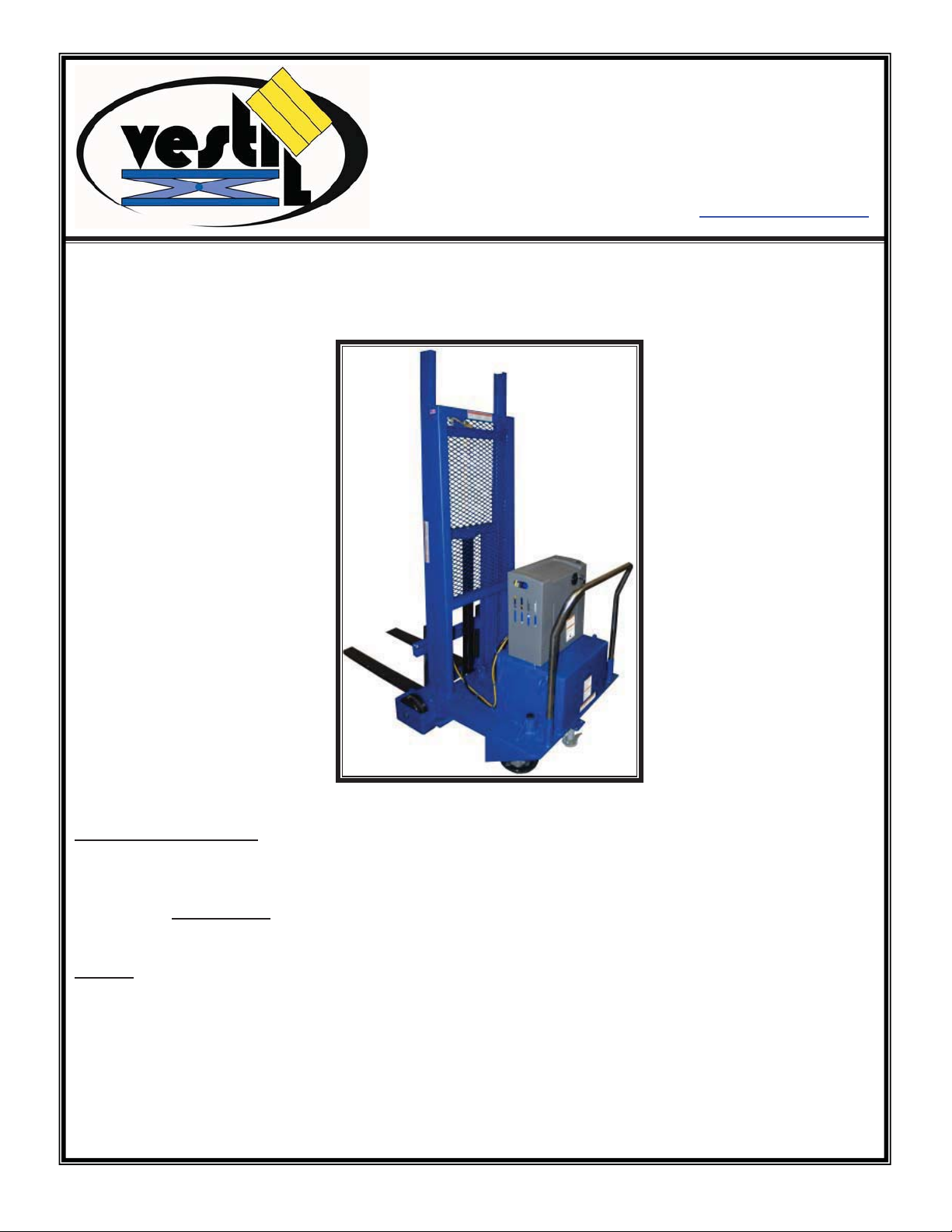
INSTRUCTION MANUAL
Receiving instructions:
After delivery, IMMEDIATELY remove the packaging from the product in a manner that preserves the
packaging and maintains the orientation of the product in the packaging; then inspect the product closely
to determine whether it sustained damage during transport. If damage is discovered during the
inspection, immediately record a complete description of the damage on the bill of lading. If the
product is undamaged, discard the packaging.
NOTES:
1) Compliance with laws, regulations, codes, and non-voluntary standards enforced in the location where
the product is used is exclusively the responsibility of the owner/end-user.
2) VESTIL is not liable for any injury or property damage that occurs as a consequence of failing to apply either: a)
the instructions in this manual; or b) information provided on labels affixed to the product.
responsible for any consequential damages sustained as a result of failing to exercise sound judgment
while assembling, installing, using or maintaining this product.
Neither is Vestil
Page 2
rev. 1/23/2013 Product manual, operation instructions.doc
SIGNAL WORDS
This manual uses SIGNAL WORDS to indicate the likelihood of personal injuries, as well as the probable
seriousness of those injuries, if the product is misused in the ways described. Other signal words call attention to
uses of the product likely cause property damage.
The signal words used appear below along with the meaning of each word:
Identifies a hazardous situation which, if not avoided, WILL result in DEATH or
SERIOUS INJURY. Use of this signal word is limited to the most extreme
situations.
Identifies a hazardous situation which, if not avoided, COULD result in DEATH or
SERIOUS INJURY.
Indicates a hazardous situation which, if not avoided, COULD result in MINOR or
MODERATE injury.
Identifies practices likely to result in product/property damage, such as operation that
might damage the product.
Each person who assembles, installs, uses, or maintains this product should read the entire manual and fully
understand the directions in advance. If after reading the manual you do not understand an instruction, ask
your supervisor or employer for clarification, because failure to adhere to the directions in this manual
might result in serious personal injury.
SAFETY GUIDELINES
Vestil diligently strives to identify foreseeable hazards associated with the use of its products. However, material
handling is inherently dangerous and no manual can address every conceivable risk. The end-user ultimately is
responsible for exercising sound judgment at all times.
Electrocution might result if any part of the product contacts electrified wires. Reduce the likelihood of
electrocution by applying common sense:
¾ DO NOT contact electrified wires with any part of this device, your body, or clothing.
¾ DO NOT use or store the product where contact with electrified wires is likely.
¾ Always inspect the usage area before using the product & implement precautions that account for conditions.
If this product is used improperly or carelessly, the operator and/or bystanders might sustain serious
personal injuries or even be killed. To reduce the likelihood of injury:
x Failure to read and understand the entire manual before assembling, installing, using or servicing the
product is a misuse of the product.
x Read the manual to refresh your understanding of proper use and maintenance procedures.
x DO NOT attempt to resolve any problem(s) with the product unless you are both authorized to do so and certain that
it will be safe to use afterwards.
x DO NOT modify the product in any way UNLESS you first obtain written approval from Vestil. Unauthorized
modifications might make the lift unsafe to use.
x DO NOT exceed the maximum rated load (see Label 287 on product).
x Inspect the product before each use.
A. DO NOT use this product if the inspection reveals structural damage. Examples of structural damage include,
but are not limited to, the following: 1) Cracked, broken or significantly deformed load-bearing members; 2)
cracked welds; 3) missing, or deformed safety chain/strap; 3) corrosion, severe wear, or other condition that
affects the ability of the product to support weight or itself. Replace each part that fails to pass an inspection,
and DO NOT use the product until it is fully restored to normal condition.
B. DO NOT use the product if any unusual noise or movement is observed. If a malfunction occurs, remove the
unit from service and notify your supervisor & maintenance personnel about the issue.
x DO NOT use this device UNLESS all product labels (see “Label Placement Diagram”) are readable and undamaged.
Proper use, maintenance, and storage are essential for this product to function properly.
o Always use this product in accordance with the instructions in this manual and consistent with any training relevant
to machines, devices, etc. used in conjunction with this product.
o Keep the product clean & dry. Lubricate moving parts.
o FOR HYDRAULIC UNITS: Do not use brake fluid or jack oils in the hydraulic system. If oil is needed, use an anti-
wear hydraulic oil with a viscosity grade of 150 SUS at 100°F, (ISO 32 cSt @ 40°C), or Dexron transmission fluid.
o Contact the manufacturer for MSDS information
Page 3
Page 4
Page 5

Page 6

Page 7

DRAWING NUMBER
E
E
DWG #:
REV.
073003JY-1A
REV.
ECR #
DATE
REVISIONS
INITIAL
073003JY-1A
25
REV.
*
16 17 19 20
26
14
10
12
3 13
27
23
11
24
22
8
16 17 18
25
21
9
6
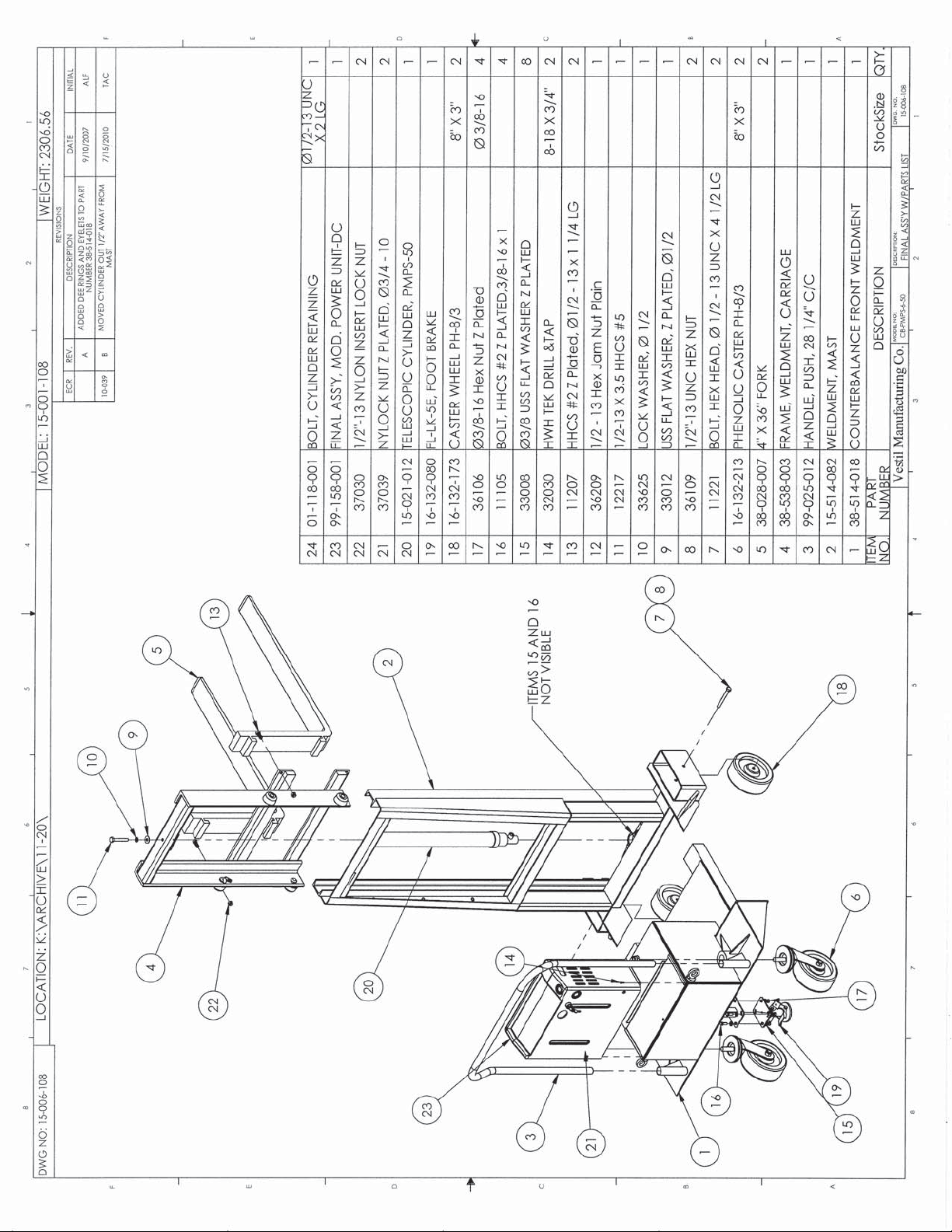
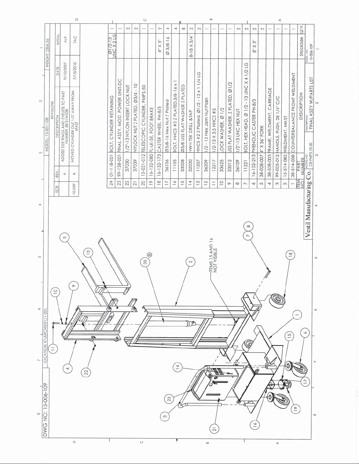
ITEM REQ PART NO. DESCRIPTION
ITEM REQ PART NO. DESCRIPTION
1 1 4JY1119 BASE
1 1 4JY1119 BASE
2 1 1212SR BATTERY CHARGER
2 1 1212SR BATTERY CHARGER
3 1 01-033-024 18/3 W/4 PIN PLUG
3 1 01-033-024 18/3 W/4 PIN PLUG
4 4 37927 TINNERMAN CLIP
4 4 37927 TINNERMAN CLIP
5 1 99- 023-001 RESERVOIR
5 1 99- 023-001 RESERVOIR
6 1 99-034-013 BATTERY STRAP
6 1 99-034-013 BATTERY STRAP
7 1 24DC36 BATTERY
7 1 24DC36 BATTERY
8 1 BV-48 BREATHER
8 1 BV-48 BREATHER
9 1 15-533-013 CABLE, BATTERY 23" BLACK
9 1 15-533-013 CABLE, BATTERY 23" BLACK
10 1 15-533-014 CABLE, BATTERY 23" RED
10 1 15-533-014 CABLE, BATTERY 23" RED
11 2 23305 SHCS UTILITY GRADE
11 2 23305 SHCS UTILITY GRADE
HIGH COLLAR LOCK WAS HER
2 33688
2 33688
2 33008 USS FLAT WASHER Z PLATED
2 33008 USS FLAT WASHER Z PLATED
12 1 99-135-011 MOTOR,12VDC
12 1 99-135-011 MOTOR,12VDC
13 1 15-022-004 RELAY, START SOLENOID
13 1 15-022-004 RELAY, START SOLENOID
14 1 HS64 CLAMP, WORM GEAR
14 1 HS64 CLAMP, WORM GEAR
15 1 BG-12V GAUGE, BATTERY INDICATOR
15 1 BG-12V GAUGE, BATTERY INDICATOR
16 3 ZB2BZ009 BASE,CONTACT BLOCK
16 3 ZB2BZ009 BASE,CONTACT BLOCK
17 3 ZB2BE101 CONTACT BLOCK N.O.
17 3 ZB2BE101 CONTACT BLOCK N.O.
18 2 ZB2BA2C
18 2 ZB2BA2C
19 1 KEY SWITCH, 2 POSITION
19 1 KEY SWITCH, 2 POSITION
20 1 01-134-007 LEGEND, ON - OFF
20 1 01-134-007 LEGEND, ON - OFF
21 1 091802JY FIBERGLASS COVER
21 1 091802JY FIBERGLASS COVER
22 1 HS52 CLAMP, WORM GEAR
22 1 HS52 CLAMP, WORM GEAR
23 1 01-143-906 PUMP
23 1 01-143-906 PUMP
24 1 01-627- 010 MANIFOLD ASSM ( SEE PAGE 2)
24 1 01-627- 010 MANIFOLD ASSM ( SEE PAGE 2)
25 2 29201 TPHMS, Z PLATED
25 2 29201 TPHMS, Z PLATED
26 2 29185 TPHMS, Z PLATED
26 2 29185 TPHMS, Z PLATED
27 4 23255 SHCS UTILITY GRADE
27 4 23255 SHCS UTILITY GRADE
4 33687 HIGH COLLAR LOCK WASHER
4 33687 HIGH COLLAR LOCK WASHER
28 1 152400-03 MOLDED CORD
28 1 152400-03 MOLDED CORD
29 1 150CCTM.OEM CONNECTOR, CHARGE
29 1 150CCTM.OEM CONNECTOR, CHARGE
30 10" 3MT ST3540 1"HOOK&LOOPPRESS SENSITIV
30 10" 3MT ST3540 1"HOOK&LOOPPRESS SENSITIV
HIGH COLLAR LOCK WAS HER
OPERTOR, BLACK, NON-ILLUM.
OPERTOR, BLACK, NON-ILLUM.
1
4
THIS PRINT IS CONFIDENTIAL AND IS
THE PROPERTY OF
THIS PRINT SHALL NOT BE USED, COPIED OR REPRODUCED
BE REVEALED ANY MANNER TO ANYONE UNLESS WRITTEN
T & S EQUIPMENT CO.
IN WHOLE OR IN PART NOR SHALL THE CONTENTS
PERMISSION IS OBTAINED FROM
T & S EQUIPMEN T CO.
REMOVE ALL BURRS AND SHARP EDGES
CONCENTRICCONCENTR
ANGLES
DECIMALS
FRACTIONSFRACTIONS
.006 TIR
+/- 0° 30'
x.xxx +/- .005
x.xx +/- .010
x.x +/- .025
+/- 1/32 +/- 1/16
.060 TIR
+/- 1° 0'
+/- .015
TOLERANCE MACHINE WELDMENT
4
7
5
28 29
30
2
T & S EQUIPMENT COMPANY
SCALE:
DATE:
MATERIAL:
NTS
07/30/03
APPROVED BY:
DC MODULAR POWER UNIT
DRAWN BY:
J.YOUNG
SIZE: A
DRAWING NUMBER:
073003JY-1A
REV:
Page 8

DRAWING NUMBER
073003-JY-1B
REV.
*
DWG #:
REV.
REV.
073003JY-1B
ITEM REQ PART NO. DESCRIPTION
ITEM REQ PART NO. DESCRIPTION
31 1
31 1
32 1 568-011-BN70
32 1 568-011-BN70
33 1 99-153-015 VALVE,CARTRIDGE,NC
33 1 99-153-015 VALVE,CARTRIDGE,NC
34 1 99-034-010 COIL, WEATHER TITE PLUG
34 1 99-034-010 COIL, WEATHER TITE PLUG
35 1 99-153-006 VALVE, PRESSURE RELIEF
35 1 99-153-006 VALVE, PRESSURE RELIEF
36 1 568-334-BN70
36 1 568-334-BN70
37 1 99-531-005 FILTER
37 1 99-531-005 FILTER
38 1
38 1
39 1 01-127-010 MANIFOLD
39 1 01-127-010 MANIFOLD
40 1 6801--06-06-NOW MJ-MAORB 90 DEG.
40 1 6801--06-06-NOW MJ-MAORB 90 DEG.
41
41
ECR #
568-015-BN70 O-RING
568-015-BN70 O-RING
99-153-038 FLOW CONTROL, 1.0 GPM
99-153-038 FLOW CONTROL, 1.0 GPM
1 99-153-011 VALVE, CHECK
1 99-153-011 VALVE, CHECK
DATE
O-RING
O-RING
O-RING
O-RING
REVISIONS
INITIAL
35
34
38
32
33
31
40
41
39
36
37
THIS PRINT IS CONFIDENTIAL AND IS
THE PROPERTY OF
THIS PRINT SHALL NOT BE USED, COPIED OR REPRODUCED
BE REVEALED ANY MANNER TO ANYONE UNLESS WRITTEN
T & S EQUIPMENT CO.
IN WHOLE OR IN PART NOR SHALL THE CONTENTS
PERMISSION IS OBTAINED FROM
T & S EQUIPMEN T CO.
REMOVE ALL BURRS AND SHARP EDGES
CONCENTRICCONCENTR
ANGLES
DECIMALS
FRACTIONSFRACTIONS
.006 TIR
+/- 0° 30'
x.xxx +/- .005
x.xx +/- .010
x.x +/- .025
+/- 1/32 +/- 1/16
.060 TIR
+/- 1° 0'
+/- .015
TOLERANCE MACHINE WELDMENT
T & S EQUIPMENT COMPANY
SCALE:
NTS
DATE:
07/30/03
MATERIAL:
APPROVED BY:
DC MODULAR POWER UNIT
DRAWING NUMBER:
073003JY-1B
DRAWN BY:
J.YOUNG
SIZE: A
REV:
Page 9

DRAWING NUMBER
REV.
DWG #:
073003JY-2A
REV.
ECR #
DATE
REVISIONS
INITIAL
073003JY-2A
REV.
9
7
21
12
10
11
14
16 17 18
16 17 19 20
ITEM REQ PART NO. DESCRIPTION
10
15
13
3
22
8
2
ITEM REQ PART NO. DESCRIPTION
1 1 4JY1119 BASE
1 1 4JY1119 BASE
2 1 ELECTRIC BOX (SEE PAGE 2)
2 1 ELECTRIC BOX (SEE PAGE 2)
3 1 21-034-005 AC ADAPTER PLUG
3 1 21-034-005 AC ADAPTER PLUG
4 4 37927 TINNERMAN CLIP
4 4 37927 TINNERMAN CLIP
5 1 99-023-001 RESERVOIR
5 1 99-023-001 RESERVOIR
6 1 MOTOR BRACE
6 1 MOTOR BRACE
4 23255 SHCS UTILITY GRADE
4 23255 SHCS UTILITY GRADE
7
7
4 33687 HIGH COLLAR LOCK WASHER
4 33687 HIGH COLLAR LOCK WASHER
8 1 BV-48 BREATHER
8 1 BV-48 BREATHER
2 29185 TPHMS, Z PLATED
2 29185 TPHMS, Z PLATED
9
9
2 29201 TPHMS, Z PLATED
2 29201 TPHMS, Z PLATED
10
10
11 2 23305 SHCS UTILITY GRADE
11 2 23305 SHCS UTILITY GRADE
2 33688
2 33688
2 33008 USS FLAT WASHER Z PLATED
2 33008 USS FLAT WASHER Z PLATED
12 1 01-627-010 MANIFOLD ASSM (SEE PAGE 2)
12 1 01-627-010 MANIFOLD ASSM (SEE PAGE 2)
13 1 01-143-906 PUMP
13 1 01-143-906 PUMP
14 1 HS52 CLAMP, WORM GEAR
14 1 HS52 CLAMP, WORM GEAR
15 1 091802JY FIBERGLASS COVER
15 1 091802JY FIBERGLASS COVER
16 3 ZB2BZ009 BASE,CONTACT BLOCK
16 3 ZB2BZ009 BASE,CONTACT BLOCK
17 3 ZB2BE101 CONTACT BLOCK N.O.
17 3 ZB2BE101 CONTACT BLOCK N.O.
18 2 ZB2BA2C
18 2 ZB2BA2C
19 1 ZB2BG4C SWITCH, KEY, 2 POSITION
19 1 ZB2BG4C SWITCH, KEY, 2 POSITION
20 1 01-134-007 LEGEND, ON - OFF
20 1 01-134-007 LEGEND, ON - OFF
21 1 99-135-003 MOTOR, ELECTRIC, 1PH
21 1 99-135-003 MOTOR, ELECTRIC, 1PH
22 6 11005 HHCS, Z PLATED
22 6 11005 HHCS, Z PLATED
6 33004 USS FLAT WASHER, Z PLATED
6 33004 USS FLAT WASHER, Z PLATED
6 33618 LOCK WASHER, Z PLATED
6 33618 LOCK WASHER, Z PLATED
6 36102 HEX NUT, Z PLATED
6 36102 HEX NUT, Z PLATED
HIGH COLLAR LOCK WASHER
HIGH COLLAR LOCK WASHER
OPERATOR, BLACK, NON-ILLUM.
OPERATOR, BLACK, NON-ILLUM.
22
22
1
6
22
4
THIS PRINT IS CONFIDENTIAL AND IS
THE PROPERTY OF
THIS PRINT SHALL NOT BE USED, COPIED OR REPRODUCED
T & S EQUIPMENT CO.
IN WHOLE OR IN PART NOR SHALL THE CONTENTS
BE REVEALED ANY MANNER TO ANYONE UNLESS WRITTEN
PERMISSION IS OBTAINED FROM
T & S EQUIPMENT CO.
REMOVE ALL BURRS AND SHARP EDGES
CONCENTRICCONCENTR
ANGLES
DECIMALS
FRACTIONSFRACTIONS
x.xxx +/- .005
x.xx +/- .010
x.x +/- .025
.006 TIR
+/- 0° 30'
+/- 1/32 +/- 1/16
.060 TIR
+/- 1° 0'
+/- .015
TOLERANCE MACHINE WELDMENT
5
4
T & S EQUIPMENT COMPANY
SCALE:
NTS
DATE:
07/30/03
MATERIAL:
APPROVED BY: DRAWN BY:
J.YOUNG
SIZE: A
AC MODULAR POWER UNIT
DRAWING NUMBER:
073003JY-2A
REV:
Page 10

DRAWING NUMBER
REV.
DWG #:
073003JY-2B
REV.
ECR #
DATE
REVISIONS
INITIAL
073003JY-2B
REV.
17
14
12
13
10
18
19
16
20
15
ITEM REQ PART NO. DESCRIPTION
ITEM REQ PART NO. DESCRIPTION
1 4 71616 TSHMS, SS
1 4 71616 TSHMS, SS
2 1 01-129-001 TRANSFORMER
2 1 01-129-001 TRANSFORMER
3 1 132560 CONTACTOR, MOTOR
3 1 132560 CONTACTOR, MOTOR
4 4 27531 PHSMS, Z PLATED
4 4 27531 PHSMS, Z PLATED
5 4 32028 HWH TEK DRILL & TAP
5 4 32028 HWH TEK DRILL & TAP
6 3" TB-TRACK RAIL, DIN
6 3" TB-TRACK RAIL, DIN
7 1 01-029-006 JUCTION BOX
7 1 01-029-006 JUCTION BOX
8 1 AB66JP PANEL, JUNCTION BOX
8 1 AB66JP PANEL, JUNCTION BOX
9 4 C500 CONNECTOR, ROMEX, 2 SCREW
9 4 C500 CONNECTOR, ROMEX, 2 SCREW
10 1 01-127-010 MANIFOLD
10 1 01-127-010 MANIFOLD
11 1 6801-06-06-NOW MJ-MAORB 90 DEG.
11 1 6801-06-06-NOW MJ-MAORB 90 DEG.
12 1 99-153-011 VALVE, CHECK
12 1 99-153-011 VALVE, CHECK
568-015-BN70 O-RING
13 1
13 1
14 1 568-011-BN70
14 1 568-011-BN70
15 1 99-153-015 VALVE,CARTRIDGE,NC
15 1 99-153-015 VALVE,CARTRIDGE,NC
16 1 99-034-008 COIL, 24V AC
16 1 99-034-008 COIL, 24V AC
17 1 99-153-006 VALVE, PRESSURE RELIEF
17 1 99-153-006 VALVE, PRESSURE RELIEF
18 1 568-334-BN70
18 1 568-334-BN70
19 1 99-531-005 FILTER
19 1 99-531-005 FILTER
20
20
568-015-BN70 O-RING
O-RING
O-RING
O-RING
O-RING
1
1
99-153-038 FLOW CONTROL, 1.0 GPM
99-153-038 FLOW CONTROL, 1.0 GPM
9
4
5
2
7
1
5
3
REMOVE ALL BURRS AND SHARP EDGES
CONCENTRICCONCENTR
THIS PRINT IS CONFIDENTIAL AND IS
THE PROPERTY OF
THIS PRINT SHALL NOT BE USED, COPIED OR REPRODUCED
T & S EQUIPMENT CO.
IN WHOLE OR IN PART NOR SHALL THE CONTENTS
BE REVEALED ANY MANNER TO ANYONE UNLESS WRITTEN
PERMISSION IS OBTAINED FROM
T & S EQUIPMENT CO.
ANGLES
DECIMALS
FRACTIONSFRACTIONS
TOLERANCE MACHINE WELDMENT
.006 TIR
+/- 0° 30'
x.xxx +/- .005
x.xx +/- .010
x.x +/- .025
+/- 1/32 +/- 1/16
.060 TIR
+/- 1° 0'
+/- .015
9
7
8
6
9
T & S EQUIPMENT COMPANY
SCALE:
NTS
07/03/03
DATE:
MATERIAL:
APPROVED BY: DRAWN BY:
J.YOUNG
SIZE: A
AC MODULAR POWER UNIT
DRAWING NUMBER:
073003JY-2B
REV:
Page 11

Page 12

rev. 1/23/2013 Product manual, operation instructions.doc
Label Placement Diagram
LIMITED WARRANTY
Page 13

rev. 1/23/2013 Product manual, operation instructions.doc
Vestil Manufacturing Corporation (“Vestil”) warrants this product to be free of defects in material and workmanship
during the warranty period. Our warranty obligation is to provide a replacement for a defective original part if the part is
covered by the warranty, after we receive a proper request from the warrantee (you) for warranty service.
Who may request service?
Only a warrantee may request service. You are a warrantee if you purchased the product from Vestil or from an
authorized distributor AND Vestil has been fully paid.
What is an “original part”?
An original part is a part used to make the product as shipped to the warrantee.
What is a “proper request”?
A request for warranty service is proper if Vestil receives: 1) a photocopy of the Customer Invoice that displays the
shipping date; AND 2) a written request for warranty service including your name and phone number. Send requests
by any of the following methods:
Mail Fax Email
Vestil Manufacturing Corporation (260) 665-1339 sales@vestil.com
2999 North Wayne Street, PO Box 507 Phone
Angola, IN 46703 (260) 665-7586
In the written request, list the parts believed to be defective and include the address where replacements should be
delivered.
What is covered under the warranty?
After Vestil receives your request for warranty service, an authorized representative will contact you to determine
whether your claim is covered by the warranty. Before providing warranty service, Vestil may require you to send the
entire product, or just the defective part or parts, to its facility in Angola, IN. The warranty covers defects in the following
original dynamic components: motors, hydraulic pumps, electronic controllers, switches and cylinders. It also covers
defects in original parts that wear under normal usage conditions (“wearing parts”): bearings, hoses, wheels, seals,
brushes, batteries, and the battery charger.
How long is the warranty period?
The warranty period for original components is 1 year. The warranty period begins on the date when Vestil ships the
product to the warrantee. If the product was purchased from an authorized distributor, the period begins when the
distributor ships the product. Vestil may extend the warranty period for products shipped from authorized distributors
by up to 30 days to account for shipping time.
If a defective part is covered by the warranty, what will Vestil do to correct the problem?
Vestil will provide an appropriate replacement for any covered part. An authorized representative of Vestil will contact
you to discuss your claim.
What is not covered by the warranty?
1. Labor;
2. Freight;
3. Occurrence of any of the following, which automatically voids the warranty:
x Product misuse;
x Negligent operation or repair;
x Corrosion or use in corrosive environments;
x Inadequate or improper maintenance;
x Damage sustained during shipping;
x Collisions or other incidental contacts causing damage to the product;
x Unauthorized modifications: DO NOT modify the product IN ANY WAY without first receiving written
authorization from Vestil. Modification(s) might make the product unsafe to use or might cause excessive and/or
abnormal wear.
Do any other warranties apply to the product?
Vestil Manufacturing Corp. makes no other express warranties. All implied warranties are disclaimed to the extent
allowed by law. Any implied warranty not disclaimed is limited in scope to the terms of this Limited Warranty.
 Loading...