

Page 1
INSTRUCTION MANUAL
FOR PREMIUM SCISSOR LIFT CARTS
MODELS COVERED: CART-300-S-FR,
CART-300-D-FR, CART-600-S-FR,
CART-600-D-FR, CART-1000-S-FR,
CART-1000-D-FR
Note:
instruction manual before using the lift table.
Owner/Operator must read and understand this
Page 2

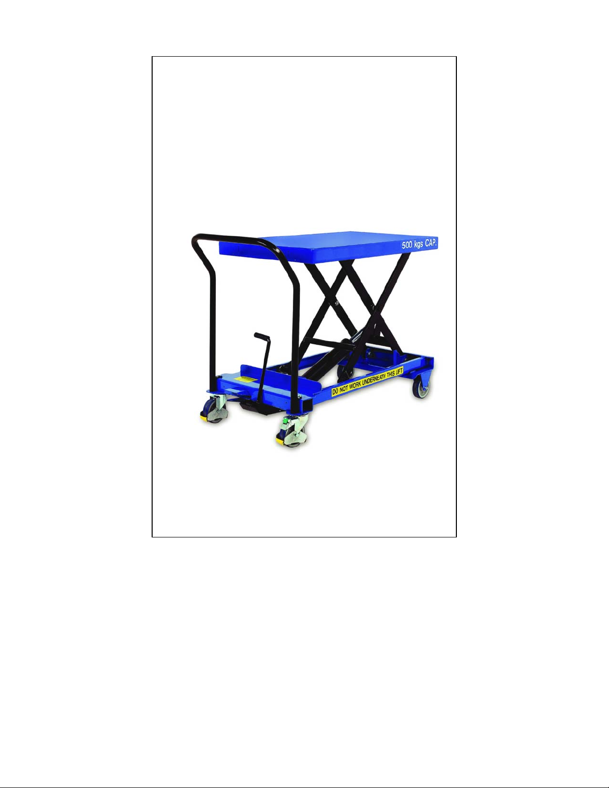
This product is a hydraulically powered lifting device
mounted on wheels. The lifting platform lifts by the
action of the scissor arms. The product is designed to
be manually positioned and operated, and to lift
goods of no more than the rated capacity in total
weight at any one time.
BEFORE USE OF THE TABLE:
~ This booklet should be read thoroughly;
~ This booklet should be passed to the safety officer to keep for
future reference;
~ Any supplied test certificates should be passed to those
responsible for your register of lifting equipment and be retained
for scrutiny by a factory inspector, insurance company etc;
~ Familiarized yourself with the table.
SAFETY:
N.B. This table has been built to EN 1570 and is accompanied by a
Test Certificate. It should be read and kept in a safe place as you
may be asked to present it by your insurance company or factory
inspector.
This table has been designed to give:
~ 30mm gap between the scissor arms to reduce risk of trapping;
~ 50mm gap between the scissor arms and the frame to reduce
risk of trapping;
~ A safe descent speed governed by an oil flow control cartridge in
the ram (even if the hydraulic hose is accidentally cut the table will
still descend at a safe speed);
~ Automatic stop lowering even if the pedal is released.
Only authorized personnel should be allowed to operate this
table. Please see section entitled USAGE for instructions for safe
usage and warnings against possible misuse.
It is dangerous to work under the platform when raised. The
table is designed for maintenance whilst in the fully lowered
Page 3

position with the platform hinged open, therefore THERE IS NO
MECHANICAL LOCKING DEVICE to stop the platform from
lowering. Please see section entitled MAINTENANCE before
attempting any kind of maintenance to the table.
If the table is damaged, deformed or performs incorrectly this
should be reported and usage discontinued. After any major
repair the table must be re-tested according to EN 1570 Annex C.
MAINTENANCE:
N.B. After any major repair the table must be re-tested according
to EN 1570 Annex C.
N.B. The only maintenance that the table usually needs is topping
up of oil and checking for damage.
Maintenance Instructions:
When the table is fully lowered the platform hinges open to allow
access to the hydraulics for topping up the oil. All hinge points
have nylon bearings and all the ball races are sealed, requiring
little maintenance. When topping up the hydraulic oil only fill with
enough oil to allow the table to lift to full height, as overfilling will
cause leakage. The hydraulic oil used in the pump ISO VG22.
The pump and ram can be removed together with the hose for
replacement or service.
Maintenance Periods:
Daily: table should be checked for obvious damage and oil leaks.
Faults should be reported.
Monthly: oil should be checked for serious leaks (oil may escape
from cylinder or from the reservoir, particularly if table is tipped,
tilted or overturned. If in doubt, check with engineer).
Annually: table should be re-tested (see EN 1570 Annex C).
Occasionally: it may be necessary to top up the hydraulic oil (e.g.
after leakage).
Page 4
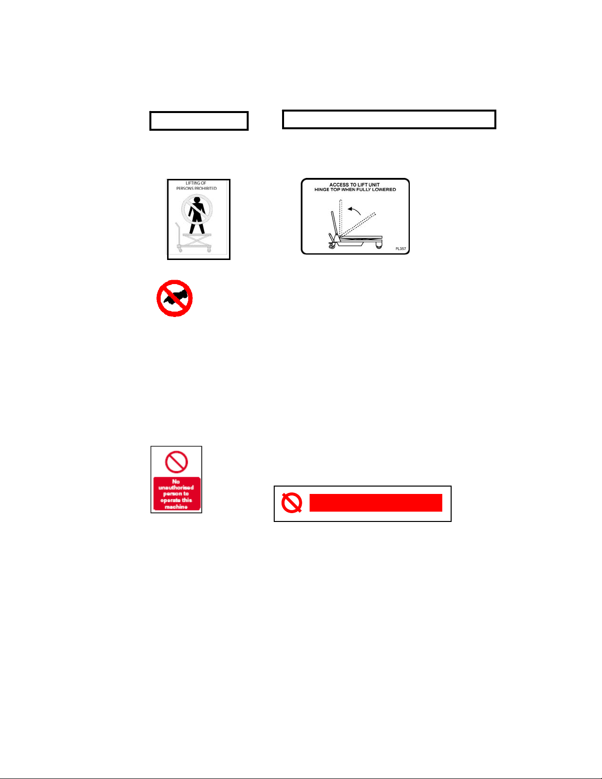
SAFETY NOTICES:
The table is labeled with the following safety notices:
300 lbs Capacity
rated capacity of the table no entry (inc. for maintenance)
DO NOT WORK UNDER THIS PLATFORM
whilst platform raised
lifting of
persons
prohibited
do not touch the
scissor arms
The table also has a serial plate, including:
~ The rated load and distribution
~ Manufacturer name and address
~ Type and serial number
~ Self weight of the table
ADDITIONAL SAFETY NOTICES:
The notice: “ONL Y AUTHORISED PERSONS ARE
ALLOWED TO OPERATE THE LIFTING TABLE”
or similar must be permanently and visibly fixed at
the control position.
access for
maintenance
by hinging
platform open
DO NOT OVERLOAD
Page 5

The notice: “DO NOT OVERLOAD” must be provided in positions
where overloading is possible.
USAGE:
Summary:
This product is a mobile scissor lift table, designed to lift goods of
no more than the rated capacity in weight, and to be pushed only
when fully lowered. This table is designed for use indoors and on a
smooth level surface.
General Instructions:
N.B. Care must always be taken when handling heavy loads or
moving a loaded table and especially if over a poor surface.
When manually handling loads the appropriate manual handling
procedures must be adhered to. Failure to do so can result in
serious injury.
Loading the platform
This table is designed to:
~ in one case lift half the rated load distributed over half the length
of the platform;
~ in another case lift a third of the rated load distributed over half
the width of the platform.
It is the responsibility of the user and operator to ensure that this
loading is not exceeded and that the load being lifted by the scissor
table is sufficiently secure as not to fall during operation of the table.
The load should be secured to table if lifting above 2000mm.
Raising the platform
Raise the platform by repeatedly operating of the foot pedal.
N.B. The brake must be applied prior to raising the table.
Lowering the platform
Lower the table by pressing and holding the lowering pedal. (The
oil flow control cartridge ensures that the designed descent is not
exceeded irrespective of the load.) The operator must ensure
that nothing and no person is in the way of the platform or the
scissor arms.
:
:
:
Page 6

Moving the table
When fully lowered, push and steer using the foldable handle.
The table is designed to be pushed only with the platform in the
fully lowered position.
The table is designed to be pushed only along a level surface.
N.B. Safety shoes must be worn by persons moving the table (to
avoid toes being crushed by the wheels).
Folding/Unfolding the handle (CART-300-S-FR)
To fold the handle down: push down on the horizontal bar at the
handle end of the table (which retains the handle) far enough for
the end of the tube to be freed and then fold the handle forward.
To raise the handle: lift the handle and depress the retaining bar to
allow the handle to click into position.
N.B. The handle must be fully locked into the vertical position prior
to use.
:
:
NOT RECOMMENDED:
DO NOT USE on ramps, hills or slopes.
DO NOT USE in wet or damp conditions.
DO NOT USE foot pedal when platform is hinged open.
DO NOT USE to lift more than the rated capacity.
DO NOT USE to lift persons. This table is not designed to lift
persons and it is the responsibility of the user and operator to
ensure that such use is prohibited.
DO NOT USE IF DAMAGED, DEFORMED OR PERFORMING
INCORRECTLY. If the table is damaged, deformed or performs
incorrectly this should be reported immediately and use should be
discontinued.
Page 7

ASSEMBLY INSTRUCTIONS:
Figure 1
1. Attach the pedal bar (Part No.4-65) to the pump unit (see
Figure 1);
● Loosen the bolt(4-64) and nut(4-39) on the pedal bar ;
● Hitch up the pedal bar assy. to the pedal bar , then rotate it to
make sure that the holes of them are in line;
● Insert the bolt across the holes, then fasten them by nut.
Figure 2
Page 8

2. Assemble the handle (Part No.3-1) (see Figure 2);
● Loosen the bolt and nut;
● Insert the bolt into the holes of the handle and chassis, then
fasten them by nut.
WARNINGS:
DO NOT work underneath the platform when raised.
DO NOT overload the table.
DO NOT exceed the load distribution limits (see USAGE section).
DO NOT adjust the overload valve.
DO NOT remove warning labels.
DO NOT invert the table or put it on its side.
DO NOT jack with the platform hinged open.
ALWAYS check for damage before use.
ALWAYS apply the brake when stationary.
ALWAYS ensure people are clear of the table before lowering.
ALWAYS beware that fingers could be trapped when raising or
lowering.
ALWAYS ensure table is fully secure during maintenance as it may
fall knocked or moved.
ALWAYS take care when handling heavy loads.
ONLY AUTHORISED PERSONS SHOULD BE ALLOWED TO
OPERATE THIS TABLE.
Page 9

TROUBLE SHOOTING:
FAULT CAUSE REMEDY
Foot pedal
will not
raise
platform.
If fault
remains.
If fault
remains.
If fault
remains.
If fault
remains.
If fault
remains.
Platform
will not
lower.
If fault
remains.
Air in hydraulics. Press and hold lowering pedal and
operate foot pedal twenty times.
Release lowering pedal.
Release plunger
remains in (causing
release ball to not
seat properly).
Table overloaded Check weight of load is within table
Oil level low. Check oil level and top up if necessary.
Insufficient air in
reservoir (oil level
too high).
Seal blown. Check by looking for leaking oil.
Platform has been
over-raised and load
is insufficient to
lower the platform.
Flow control
cartridge valve is
jammed.
Check that release plunger is not
stuck, if so lightly lubricate and attempt
to operate pedal.
Check release plunger is not damaged
or deformed and jammed. Attempt to
straighten if necessary.
capacity.
DO NOT OVERFILL (see directly
below).
Remove reservoir cap, remove excess
so that oil level is no higher than 8mm
below the bottom of the filler tube,
operate pedal to raise platform to full
height and replace cap.
Replace seal if necessary.
Whilst holding release pedal apply
additional load onto the platform to aid
its descent.
Unscrew hose connection, remove
flow control cartridge and check that its
plunger is still movable.
Page 10

EXCLUSIONS FROM STANDARD EN 1570:
The standard EN 1570 does not apply to the following
equipment:
~ Permanently installed lifting tables, serving specific levels of a
building and fitted with a car.
~ Permanently installed lifting tables, serving specific levels of a
building, not fitted with a car but with vertical travel of more than
2,0m
~ Power operated lifting platforms for persons with impaired
mobility.
~ Lifting tables for Airport Ground Equipment.
~ Lifting tables for marine use.
~ Mobile elevating work platforms.
~ Vehicle lifts (for maintenance.)
~ Mobile lifting tables used for fire fighting.
~ Mobile lifting tables used as fork lift trucks, pallet trucks and order
pickers.
~ Mobile lifting tables with a travelling speed of more than 1,6 m/s.
~ Rail dependent storage and retrieval equipment.
~ Theatre stage lifts.
Page 11

The standard EN 1570 does not establish the
additional requirements for:
~ Operation in severe conditions (e.g. extreme climates, freezer
applications, strong magnetic fields.).
~ Operation subject to special rules (e.g. potentially explosive
atmospheres, mines).
~ Handling of loads, the nature of which could lead to dangerous
situations (e.g. molten metal, acids, radiating materials, especially
brittle loads).
~ Hazards occurring during construction, transportation and
disposal.
~ Equipment installed on the load platform or replacing it.
~ Integration into systems or other machines, control from more
than two control stations etc.
~ Cable-less controls.
~ Lifting tables where the hydraulic pressure is derived directly
from gas pressure.
TECHNICAL DETAILS:
Hydraulic Fluid: ISO VG22
Hydraulic Hoses:
TRACTOR 1T EN 853 1SN
Insert: MF2000 – Multifit Type
Tube: Oil resistant synthetic rubber
Reinforcement: One high tensile steel braid
Cover: Environmental resistant synthetic rubber
Max. working pressure: 225 bar (3260 psi)
Page 12

MODEL NO. CART-300-S-FR CART-300-D-FR CART -60 0-S-F R CART-600-D-FR CART-1000-S-FR CART-1000-D-FR
Built to: EN1570 EN1570 EN1570 EN1570 EN1570 EN1570
Operation: Manual Manual Manual Manual Manual Manual
Max Capacity: 300 lbs 300 lbs. 600 lbs. 600 lbs. 1000 lbs. 1000 lbs.
Platform Size: 17¾” x 30” 19⅝” x 33” 20” x 31⅞” 23¼” x 33” 24” x 40½” 24” x 40½”
Lowered Height: 10” 17” 13 3/16” 11¾” 13⅜” 11⅝
Raised Height: 30 11/16” 55⅞” 33” 53” 35 7/16” 61”
Handle Height: 37” 33⅞” 33⅞” 33⅞” 36 7/16” 36 7/16”
Weight: 95 190 190 210 250 320
Scissor Arms: Single Double Single Double Single Double
Page 13

Parts List
REF PART DESCRIPTION QTY REF PART DESCRIPTION QTY
1 Table assembly 1 5 Chassis assembly 1
2 Scissor assembly 1 6 Universal wheel assembly 2
3 Handle assembly 1 7 Fixed wheel assembly 2
4 Pump Unit 1
Page 14

Scissor Assembly:
REF PART DESCRIPTION QTY REF PART DESCRIPTION QTY
2-1
2-2
2-3 Self-locking nut M16 12 2-11 Tension pin 5×30 2
2-4 Nylon bush 2 2-12 Retainer ring 4
2-5 Bolt 4 2-13 Ball bearing 4
2-6 Nylon washer 24 2-14
2-7 Nylon bush 16 2-15
2-8 Hexagon head bolt M16×75 8 2-16 Washer 20 2
Outside scissor assembling
(upper)
Inside scissor assembling
(upper)
2 2-9 Nylon bush 2
2 2-10 Piston rod 1
Outside scissor assembly
(lower)
Inside scissor assembly
(lower)
2
2
Note: Items 2-1 to 2-16 available only as complete kit;
Page 15

Handle assembly:
REF PART DESCRIPTION QTY
3-1 Handle assy. 1
3-2 Hexagon head bolt M10×25 2
3-3 Self-locking nut M10 2
Note: Items 3-1 to 3-3 available
only as complete kit;
Pump Unit:
Page 16

REF PART DESCRIPTION QTY REF PART DESCRIPTION QTY
4-1 Dust cover φ30×φ38×5
4-2 "O" ring φ30×2.65
4-3 Cylinder Cover
4-4 "O" ring φ67×2.65
4-5 Piston bar
4-6 Positioning bush
4-7 Nylon washer
4-8 Oil-sealing for UN-hole
4-9 Retainer ring
4-10 Retainer for guiding ring
4-11 Guiding ring
4-12 Retainer ring
4-13 Cylinder welding
4-14 "O" ring φ10.6×2.65
4-15 Bolt for oil feeder
4-31 Torsion spring
4-32 Tension pin 4x32
4-33 Self-locking nut M5
4-34 Guiding bush for bar
4-35 Lever
4-36 Bar
4-37 Dropping pedal
4-38 Washer
4-39 Self-locking nut M8
1
4-16 Speed control valve
1
4-17 Composite packing washer
1
4-18 Bolt of speed control valve
1
4-19 Bolt of single-way valve
1
4-20 Composite packing washer
1
4-21 Spring for single-way valve
1
4-22 Single-way valve
1
4-23 Steel ball φ8
1
4-24 Bolt
1
4-25
1
4-26 Inner Hexagon Bolt M10
1
4-27 Spring for control valve
1
4-28 Spring base
1
4-29 Steel ball φ5
1
4-30 Bolt M6
1
4-49 Pin for Hydraulic cylinder
1
4-50 Split pin
1
4-51 Composite packing washer
1
4-52 Pump
1
4-53 "Y" sealing φ24×φ16
1
4-54 "O" ring φ16×2.65
1
4-55 Dust cover φ24×φ16
1
4-56 Spring
1
4-57 Plunger assy.
USS composite packing
washer
1
1
1
1
1
2
1
1
1
1
1
1
1
1
2
1
1
1
1
1
1
1
1
1
Page 17

4-40 Returning oil bar
4-41 "O" ring φ7.1×1.8
4-42 Spring
4-43 Guiding bush
4-44 "O" ring φ10×1.8
4-45 Composite packing washer
4-46 Steel ball φ6.5
4-47 Tension pin 5×18
4-48 Tension pin 5×30
Note: Items 4-1 to 4-66 available only as complete kit;
Universal wheel assembly:
REF PART DESCRIPTION QTY REF PART DESCRIPTION QTY
6-1 Self-locking nut M12 2 6-2 Castor with brake 2
Note: Items 6-1 to 6-2 available only as complete kit;
1
4-58 Retainer ring
1
4-59 Pin
3
4-60 Nylon bush
1
4-61 Lifting-rod welding assembly
1
4-62 Spring
1
4-63 Pedal bar
1
4-64 Hexagon head bolt M8×35
1
4-65 Pedal bar
2
4-66 Protecting sleeve
2
1
2
1
1
1
1
1
1
Page 18

Fixed wheel assembly:
REF PART DESCRIPTION QTY REF PART DESCRIPTION QTY
7-1 Hexagon head bolt M10x70
7-2 Outside positioning bush
7-3 Dust cover
Note: Items 7-1 to 7-6 available only as complete kit;
2
7-4 Bearing bush
4
7-5 Roller (PU)
4
7-6 Self-locking nut M10
2
2
2
 Loading...