

Page 1
08/05 01-126-106.doc
O
VESTIL MANUFACTURING CORP.
2999 N. Wayne St., Angola, IN 46703
Ph: 260-665-7586 · Fax: 260- 6 65-1339
E-mail: sales@vestil.com · Website: www.vestil.com
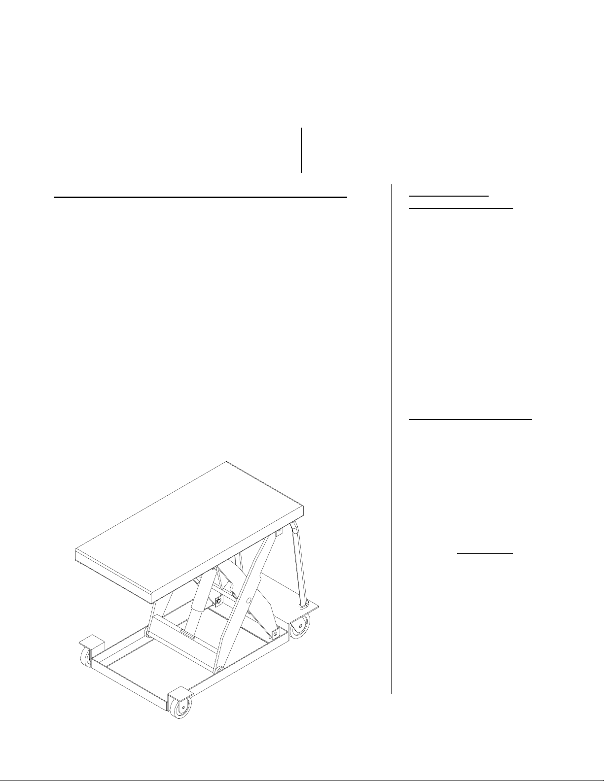
CART-23 & -24, ALL MODELS
Serial number ____________
Operation Instructions ……………………….……… 2-3
Routine Maintenance & Safety Checks ……………… 4
Exploded Power Unit Drawing & BOM ………......... 5-6
Electrical & Hydraulic Diagrams …………................ 7-8
IMPORTANT NOTES, WARNINGS AND SAFETY INSTRUCTIONS
Ensure that all employees understand and follow the following.
* Failure to read and understand this owner’s manual before using or
servicing the cart constitutes a misuse of the product. All persons who
will use or care for this product must be familiar with this material.
o The load must be removed and the platform fully lowered before any
work is performed on the cart.
o Ensure that all safety and warning labels stay in place and are legible.
o Do not use the cart if any damage or unusual noise is observed.
o Always watch the platform and the load carefully when the cart is in
operation.
o The cart is intended for use only on compacted, improved surfaces.
o Do not use brake fluid or jack oils in the hydraulic system. If oil is
needed, use an anti-wear hydraulic oil with a viscosity grade of
150 SUS at 100°F, (ISO 32 cSt @ 40°C), or Dexron transmission fluid.
o Contact the manufacturer for any needed MSDS information.
♦ Do not perform any modifications to the cart without the manufacturer’s
approval. Failure to receive authorization for changes to the equipment
could void the warranty.
♦ Maintenance and repairs are to be done only by personnel qualified to
perform the required work. Consideration will not be given for warranty
repair charges without prior written authorization by the manufacturer.
Power Unit’s Operation ………………...…..………..... 9
Troubleshooting …………………………....………… 10
Safety Label Identification .............................................11
Warranty …………………………………….……..…. 12
WNER’S
MANUAL
WHEN ORDERING
REPLACEMENT PARTS:
We take pride in using quality
parts on the equipment we
manufacture. We are not
responsible for equipment
problems resulting from the use
of unapproved replacement
parts.
To order replacement or
spare parts for this equipment,
contact the factory.
In any communication with
the factory please be prepared
to provide the machine’s serial
number, which is indicated on
the machine dataplate.
RECEIVING INSTRUCTIONS
Every unit is thoroughly
tested and inspected prior to
shipment. However, it is
possible that the unit could
incur damage during transit.
Inspect the unit closely when
it arrives. If you see evidence
of damage or rough handling to
either the packaging or to the
product when it is being
unloaded, immediately
note of it on the Bill Of Lading!
It is important that you
remove the product’s packaging
upon its arrival to ensure that
there is no concealed damage
or to enable a timely claim with
the carrier for freight damage.
Also verify that the product
and its specifications are as
ordered.
make a
ESTIL MFG. CO. 1
V
Page 2

11/13/02 08/17/05 CART manual, power unit operation.doc
OPERATION INSTRUCTIONS – CART-23, -24
o Ensure that all employees involved in the operation of this cart understand and follow these instructions!
The standard model CART is suitable for use in most industrial and commercial locations. It is intended to be
used to transport and lift stable, evenly-distributed, non-hazardous loads and containers with rigid sides having a
size or footprint approximately the same size as the platform.
Loading:
The load rating, in pounds, is shown on the machine dataplate located on the left corner of the push handle
end of the platform. It indicates the net capacity of the CART with a static load that is centered and evenly
distributed on the platform.
Warning: The platform’s rollers are not captured. Therefore, do not overhang any load at the hinged end of the
platform – that could cause the roller end of the platform to tip up and dump the load. For applications
involving side or end edge loading, consult the factory.
Note: The addition of any ancillary equipment to the cart by third parties must be taken into account when
determining the maximum working load to be placed on the platform.
Warning: Do not exceed the cart’s load ratings. Injury to personnel or permanent damage to the cart could
result from exceeding the listed capacity.
Operation:
Inspect the perimeter pinch point guards’ operation daily (DC units).
Warning: Keep all personnel clear of the machine when it is in operation. Be certain no part of any pers on or
object is under any part of the platform before lowering the unit.
Caution: Always carefully watch the platform and any load on it when it is in operation.
Do not exceed a rate of two feet per second when transporting a load with the cart.
o The standard manually-powered CART is furnished with a two-speed foot pump. Under empty or low load
conditions, the pump pushes a higher volume of fluid to the cylinder and thus lifts the platform with fewer foot
strokes. With a moderate to full load, the pump will automatically reduce its output in order to generate the
required hydraulic pressure.
To lift the platform, simply repeatedly press the foot pump’s foot treadle. To lower the platform, press the
small lever at the left corner of the pump with your toe. The unit will hold its position when the lowering lever
is released.
o The standard DC-powered CART is furnished with a constant-pressure (dead-man style) pushbutton control.
Pressing the “UP” pushbutton will turn on the power unit to raise the platform. The platform will raise only
while the control is pressed. Upon releasing the control, the platform will stop and hold its position.
Pressing the “DOWN” pushbutton will energize the lowering valve to allow the platform to descend by gravity
(the motor does not run). Again, releasing the control will stop the platform movement, and the unit will hold
its position.
Caution: Never use the cart if any damage or unusual noise is observed, if it is in need of repair s, or if it seems
to be malfunctioning. Notify your supervisor or maintenance personnel if you notice anything out of the
ordinary.
On DC-powered units, attempting to raise the lift when the battery is low will cause the motor relay
protection to prevent the motor’s operation. Adequate battery voltage is indicated by a green LED on the motor
relay. See the next page for more notes regarding operation of battery-powered units.
Ensure that all safety and warning labels stay in place and are legible. Refer to the labels page in this manual.
2 of 12
Page 3

11/13/02 08/17/05 CART manual, power unit operation.doc
ADDITIONAL INSTRUCTIONS FOR BATTERY-POWERED UNITS
Note: If this product has the 24V powered traction-drive option, consult that option’s information for more
specific details regarding the batteries and battery charger.
Warning!
! Working with or near lead acid batteries is dangerous. Batteries contain sulfuric acid and produce explosive
gases. A battery explosion could result in loss of eyesight or serious burns.
! Do not smoke or allow a spark or flame near batteries. Charge batteries in locations that are clean, dry, and
well ventilated. Do not lay tools or anything metallic on top of any battery. All repairs to a battery must be
made by experienced and qualified personnel.
! When working with batteries, remove personal items such as rings, bracelets, necklaces, and watches.
Batteries can produce enough energy to weld jewelry to metal, causing a severe burn.
! Always have fresh water and soap nearby in case battery acid contacts skin, clothing, or eyes.
! Operating the battery with a low battery voltage can cause premature motor contact failure.
! Do not expose the lift or the charger to rain or adverse conditions.
! Replace defective cords or wires immediately.
! Check the battery’s water level frequently.
Battery Charger Operating Instructions
Never operate the charger with either of the cables coiled. Operating a battery charger with the cord either
coiled or wrapped around itself could cause the cord to overheat, melt, and cause a short-circuit or a fire.
Connection: the ribbed wire of the charger’s output cord must be connected to the battery’s negative (-)
terminal. The non-ribbed wire (with words printed on it) must be connected to the battery’s positive (+)
terminal.
When properly connected, the charger will indicate the status of its output:
Flashing green LED – the charger is not seeing a good connection to the battery.
Solid yellow LED – the charger is providing charging current to the battery.
Solid green LED – the charger is maintaining a fully charged battery.
Plug the charger into a standard 115V receptacle. If an extension cord must be used, keep it as short as
possible.
Caution: Remember to unplug the charger before moving the equipment. Failure to do so could cause
damage to cords, receptacles, and other equipment.
The battery charger can be left connected to the battery indefinitely without risk of harming the battery.
Troubleshooting:
If the unit does not operate, check all of the wiring connections to make sure they’re both mechanically and
electrically sound – specifically at the battery, the motor, and at any location a wire is connected to the chassis.
Also, make sure the quick-connect plug on the end of the pendant control cord is plugged in correctly (if
applicable).
A fully charged lead acid battery in good condition at room temperature should read 12.65 volts. At 11.9
volts it is considered to be fully discharged and in need of charging. When checking battery voltage, wait at
least 1/2 hour after the charger has been turned off before checking the batter y ’s voltage.
If the batteries don’t seem to be taking a charge, check the charger’s 115V supply circuit and the
charger’s output with a voltmeter. If all check okay, confirm the battery’s state of charge using a hydrometer or
a voltmeter.
3 of 12
Page 4

11/13/02 08/17/05 CART manual, power unit operation.doc
ROUTINE MAINTENANCE & SAFETY CHECKS, CART-23, -24
o Warning: Care should be taken to identify all potential hazards and comply with applicable safety
procedures before beginning work.
o Warning: Remove any load, raise the platform, and install maintenance props before beginning any
inspections or work on the unit.
o Only qualified individuals trained to understand mechanical devices and their associated electrical and
hydraulic circuits should attempt troubleshooting and repair of this equipment
(A) Inspect daily for:
1.) Frayed wires (DC units).
2.) Oil leaks.
3.) Pinched or chafed hoses.
4.) Damage or structural deformation to the structural members, the cylinder brackets, etc.
5.) Unusual noise or binding, or evidence thereof.
6.) Proper functioning of all limit switches, including those on the perimeter pinch point guard (DC units).
(B) Inspect monthly for:
1.) The oil level. Oil should be 1” to 1½” below the reservoir’s fill hole with the lift in the fully lowered
position.
2.) Oil leaks.
3.) Worn or damaged electrical wires (DC units) or hydraulic hoses.
4.) Pivot point wear.
5.) Rollers’ looseness and wear.
6.) Integrity of the retaining hardware on all rollers and on all pivot point pins.
7.) Looseness, wear, or damage to the casters’ bearings, mounting hardware, or su rface material.
8.) Proper water level in the battery (DC units only.)
9.) Unusual noises.
10.) All the information, safety, and warning labels being in place and in good condition.
11.) The need to clean off dirt and debris.
(C) Yearly inspection
The oil should be changed if the oil darkens, becomes gritty, or turns a milky color (indicating the presence
of water). Replace with an anti-wear hydraulic oil with a viscosity grade of 150 SUS at 100°F, (ISO 32 at
40°C). Ex: AW 32 or HO 150 hydraulic oil, or a non-synthetic transmission fluid. You may use a synthetic
transmission fluid if you flush the system with the synthetic fluid before filling the reservoir.
4 of 12
Page 5

11/13/02 08/17/05 CART manual, power unit operation.doc
MODULAR POWER UNIT PARTS BREAKDOWN -- DC-1
Note: Motors, cylinders, and pumps can vary by model. Consult the manufacturer to determine the exact
part numbers for these items.
5 of 12
Page 6

11/13/02 08/17/05 CART manual, power unit operation.doc
MODULAR POWER UNIT PARTS BREAKDOWN -- DC-2
Note: Motors, cylinders, and pumps can vary by model. Consult the manufacturer to determine the exact
part numbers for these items.
6 of 12
Page 7

11/13/02 08/17/05 CART manual, power unit operation.doc
ELECTRICAL DIAGRAM -- MODULAR POWER UNIT
o Warning: Care should be taken to identify all potential hazards and comply with applicable safety procedures
before beginning work. Fully lower or secure the forks, and ensure that all system pressure and power have
been removed, before attempting to work on the electrical or hydraulic systems.
o Fully lower the forks before beginning any inspections or work on the unit.
o Only qualified individuals trained to understand mechanical devices and their associated electrical and
hydraulic circuits should attempt troubleshooting and repair of this equipment
7 of 12
Page 8

11/13/02 08/17/05 CART manual, power unit operation.doc
HYDRAULIC DIAGRAM – LIFT-HOLD-LOWER CIRCUITS
o Warning: Care should be taken to identify all potential hazards and comply with applicable safety
procedures before beginning work. Fully lower or secure the for k s, and ensure that all system pressure and
power have been removed, before attempting to work on the electrical or hydraulic systems.
o Fully lower the unit before beginning any inspections or work.
o Only qualified individuals trained to understand mechanical devices and their associated electrical and
hydraulic circuits should attempt troubleshooting and repair of this equipment
o Caution: Do not use brake fluid or jack oils in the hydraulic system. If oil is needed, use an anti-wear
hydraulic oil with a viscosity of 150 SUS at 100°F (ISO 32 @ 40°C), or non-synthetic transmission fluid.
8 of 12
Page 9

11/13/02 08/17/05 CART manual, power unit operation.doc
THE POWER UNIT’S OPERATION – CART-23, -24
The electric / hydraulic scissor lift utilizes an electric motor directly coupled to a gear-type hydraulic pump
to produce the needed fluid pressure and flow to allow the cylinders to perform the work of lifting the platform
load.
A hydraulic manifold houses the hydraulic control components, and is bolted directly onto the gear pump.
The power unit’s hydraulic components are all rated for 3,000 psi working pressure.
¬ Important parts of the power unit include:
• The electric motor. Operates on a 12 VDC battery.
• The gear pump. Its shaft is coupled directly to the shaft of the electric motor.
• The check valve. Its purpose is to prevent the backflow of fluid through the pump. In this way it allows the
platform to be held at a given elevation indefinitely.
• The pressure relief valve. Its job is to open a path for fluid to flow back to the reservoir in the event that
the fluid pressure built up by the pump exceeds 3,000 psi.
• The lowering solenoid valve. This is an electrically-operated cartridge valve. It contains a screen to keep
contaminants from entering the valve.
• The pressure-compensated flow control spool. This rests under the lowering valve, and regulates the fluid
flow back to the reservoir when the valve opens. It allows the table to always lower at the same rate
regardless of whether there is a load on the platform or not.
• The hydraulic lift cylinder(s). These are single-acting cylinders.
• The safety velocity fuse. This is a device that is installed in the cylinder’s hose port. It closes quickly in the
event of a catastrophic hose failure to prevent the lift from collapsing down. The platform remains
stationary until pressure is reapplied to the system.
• The hydraulic fluid. The system uses HO150 hydraulic fluid. Any anti-wear hydraulic fluid with an SUS
viscosity of 150 - 200 at 100°F (SAE viscosity grade of 32) such as AW-32 or Dexron transmission fluid are
acceptable.
When the platform is to be raised, press the “UP” pushbutton. The motor turns, which in turning spins the
hydraulic gear pump. Oil is drawn from the reservoir through the suction filter and into the pump. The pump
pushes the then-pressurized oil through the check valve and out to the lift cylinders.
When the platform is to be lowered, press the “DOWN” pushbutton. The lowering valve opens, bypassing the
check valve and allowing the oil in the cylinders to return back to the reservoir through the return hose. The
rate at which the platform lowers is regulated by the internal pressure-compensated flow spool.
¬ In the event that the platform creeps down slowly after releasing the “DOWN” control, it will be necessary
to remove the lowering cartridge valve for inspection and cleaning, as follows:
♦ Remove any load from the platform.
♦ Raise the lift and then lower the maintenance props. Guide the props into the cylinder push assembly as you
lower the platform. Hold the DOWN pushbutton until the lift rests on the props.
♦ Remove the nut holding the solenoid coil on the valve stem, the n remove the coil, and then unscrew the
valve from the manifold.
Inspect the valve for contaminants, and the valve’s o-rings and back-up washers for cuts, tears, or other
♦
damage.
♦ With the valve immersed in mineral spi rits or kerosene, use a thin tool such as a small screwdriver or a small
hex wrench to push the poppet in and out several times from the bottom end of the valve. The valve should
move freely, about 1/16” from closed to open position. If it sticks in, the valve stem could be bent and will
need to be replaced if it doesn’t free up after cleaning. Blow the valve off with a compressed-air gun while
again pushing the poppet in and out.
♦ Inspect the bottom of the manifold’s valve cavity for contaminants.
♦ Again with the thin tool, press on the middle of the flow control spool located in the bottom of the cavity. It
should move down and back up freely.
♦ Reinstall the valve into the manifold, tightening the valve with approximately 20 lb-ft of torque.
¬ If the platform lowers extremely slowly, or not at all, the cylinder’s velocity fuse could be closing. This can
be caused by air in the hydraulic cylinders. To bleed the air from the system:
♦ Remove any load from the platform.
♦ Raise the lift and then lower the maintenance props. Guide the props into the cylinder push assembly as you
lower the platform. Hold the DOWN pushbutton until the lift rests on the props.
♦ Pull the bottom of the cylinder out of the push assembly and raise the end up higher than any other part of
the hydraulic system. Rotate the cylinder so the hose port is pointing up.
♦ Loosen the hose fitting ½ turn, then “jog” the motor. Oil and air will sputter from the loose fitting – once
no air is observed, tighten the fitting and replace the cylinder into the push assembly.
9 of 12
Page 10

11/13/02 08/17/05 CART manual, power unit operation.doc
TROUBLESHOOTING GUIDE -- CART-23, -24
Warning: Before performing any task, always remove any load and lower the platform fully to the floor.
* Check the DC notes page for troubleshooting other problems specific to batt ery-powered units.
Consult the factory for problems at time of installation, or for any problems not addressed below.
Problem:
Power unit doesn’t run when
“UP” button is pressed (DC
units).
Motor runs, platform doesn’t
move (DC units).
Motor hums or pump squeals,
but the platform does not
move, or the platform moves
only slowly (DC units).
Spongy or jerky platform
movement.
Platform won’t lower. Solenoid coil is bad or connector
Platform lowers too slowly. Pinched hose.
Platform raises, then drifts
down.
Possible cause(s): Action:
Upper-travel limit switch is
engaged or bad.
Bad motor relay coil.
Battery voltage low.
Control cable’s connector is
loose.
Test with meter; replace if bad.
Test with meter; replace if bad.
If LED on motor relay is not on,
check battery voltage with
meter.
Check quick-connect plug.
Pump has gone bad. Consult factory.
Platform overloaded.
Pressure relief opening at full
pressure.
Verify that the load doesn’t
exceed the table’s capacity.
Check for structural damage or
binding of the scissor legs,
etc.
Check for platform overload
condition.
Excessive air in the hydraulic
cylinders.
Bleed air per procedure
described in this manual.
Check with meter. Check quickis loose (DC units).
Solenoid valve or suction hose
screen plugged (DC units).
Physical blockage of the
structure.
connect plug.
Remove and inspect. Clean per
instructions in this manual.
Inspect for foreign material or
objects that might block the
leg set or its rollers.
Check pressure, supply, and
Flow control spool sticking.
Velocity fuse locking (platform
only slowly creeps down).
Contamination holding open the
lowering valve or the check
return hoses for kinks.
Remove plug from FC port; push
on flow spool to ensure it is
fully pressed into the cavity.
Same as for jerky platform
movement.
Remove and inspect. Clean per
instructions in this manual.
valve.
10 of 12
Page 11

11/13/02 08/17/05 CART manual, power unit operation.doc
SAFETY LABEL IDENTIFICATION
* Product safety signs or labels should be periodically inspected and cleaned by the product users as necessary to
maintain good legibility for safe viewing distance -- ANSI 535.4 (10.21). Contact the manufacturer for
replacement labels.
CART-2x-1x-DC
CART-2x-1x-M
11 of 12
Page 12

11/13/02 08/17/05 CART manual, power unit operation.doc
POWERED PRODUCTS’ WARRANTY
ONE YEAR LIMITED WARRANTY
The manufacturer warrants for the original purchaser against defects in materials and workmanship under
normal use one year after date of shipment (not to exceed 15 months after date of manufacture). Any part that
is determined by the manufacturer to be defective in material or workmanship and returned to the factory,
shipping costs prepaid, will be, as the exclusive remedy, repaired or replaced at our option. Labor costs for
warranty repairs and/or modifications are not covered unless pre-approved by the manufacturer or done at the
manufacturer’s facilities. Any modifications performed without prior written approval of the manufacturer may
void warranty. This limited warranty gives purchaser specific legal rights which vary from state to state.
All specifications are subject to change without notice.
LIMITATION OF LIABILITY
To the extent allowable under applicable law, the manufacturer’s liability for consequential and incidental
damages is expressly disclaimed. The manufacturer’s liability in any event is limited to, and shall not exceed,
the purchase price paid. Misuse or modification may void warranty.
Warranty does not cover labor or consequential damages including, but not limited to, business interruption
costs, lost profits, or lost business opportunities.
WARRANTY DISCLAIMER
The manufacturer has made a diligent effort to accurately illustrate and describe their products. However, such
illustrations and descriptions are for the sole purpose of identification, and do not express or imply a warranty
that the products are merchantable or fit for a particular purpose, or that the products will necessarily conform
to the illustrations or descriptions.
The provisions of the warranty shall be construed and enforced in accordance with the Uniform Commercial Code
and laws as enacted in the State of Indiana.
DISPOSITION
Our company will make a good faith effort for prompt correction or other adjustment with respect to any
product that proves to be defective within the Limited Warranty Period. Warranty claims must be made in
writing within said year.
12 of 12
 Loading...