

Page 1
INSTRUCTION
MANUAL
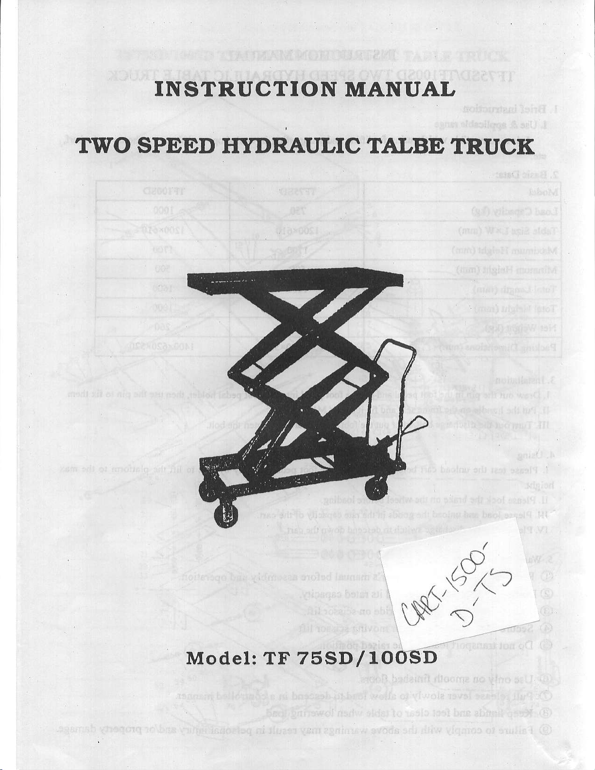
TWO SPEED
ITYDRAULIC TALBE
TRUCK
Model: TF 7sSD/TOOSD
Page 2
INSTRUCTIONMANUAL
TF?sSDIFIOOSD
L Brief
I. Usc
atc.
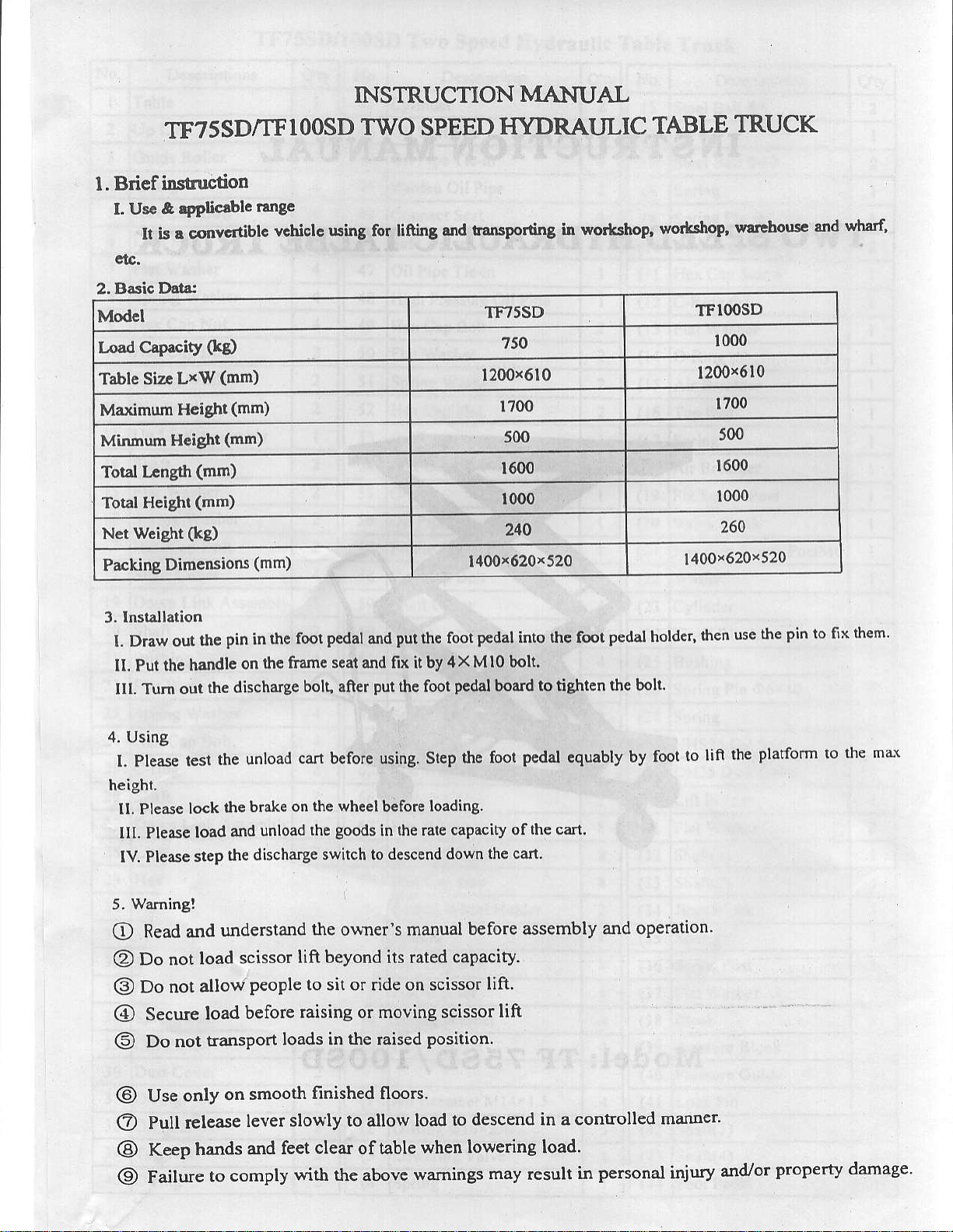
2. Basic Dda:
Modcl
Losd Clpacity
Table Siz.
Maximum
Minmum
Tot3l
Total Height
Net Weight
Packing Dimensions
instruction
& lpplicdblc
It is s cqrvc
(kg
(!tln)
LxW
Hcight
Height
lrngth
(mm)
(mm)
(k8)
(mm) 1700
(mm)
FTYDRAI.JLIC
TF75SD
r.ng.
v.hicla uting fot linilg
ibl.
TWO SPEED
.trd tansPorting
750
1200x610
500
1600
1000
240
(mm) 1400r 620
in wo*shoP,
x
520
TABLE
wortslpP,
TRUCK
watlhous'
TFIOOSD
1000
1200x610
1700
500
1600
1000
260
1400x620x520
snd
wharf,
3. lnslallation
I. Draw out
Il. Put the handlc
IIl. Tum
4. Using
l. Please
height.
tl. Pledre
lll. Please
lv. Please
Warning!
5.
Read and
O
Do not
@
Do not
@
Secure
@
Do
@
the
the
out
tesl
lock
load
slep
load
allow
load
not transport
pin
the foot
in
framc scal and fix it by 4
the
on
discharge
unload
the
brake on
the
and
discharge
lhe
bolt, aner
can before using. Step
unload
understand
scissor
lift beyond its rated
people to sit
before
raising or moving scissor
loads
pedal
the wheel
goods
the
swilch
the
o\rner's manual
put
and
put
thc foot
before
the rate capacity ofthe
in
to descend
or ride on
in the
raised
foot
the
x
Pcdal
lhe foot
loading.
down the
befo.e assembly
capacity.
scissor
position
p€dal
into the foot
Mlo bolt.
board to tighten
pcdal
cafi.
can
lift.
lift
pedal
thc bolt.
equably
by fool
and operation
holder,
to
then
lifi
pin
the
use
platform to the
the
to fix lhem'
ma\
@
@
@
@
only
Use
release
Pull
Keep
hands
Failure
smooth
on
lever sloely
and
comply
to
finished floors.
to
allolv
feet clear oftable
with the above
load to
descend in a conEolled
when lowering load.
wamings
may
result
personal
in
manner
injury
and/or
property damage
Page 3

TT'7sSD/IOOSD
TWO
SPEED EYDRAT'LIC
6
7
TABI.E TRUCI(
3!
.4.
(::
t<2
36
'-.\
F#A
(11t9(e
h{tK
(l
r!5
ll
r
r6l
7.
'/.';
i!
Jo
js
ir
rii"
gn
a:s--r
-73
*75
ii
il
li
li
Page 4

TF75SD/I00SD
Two Speed
Hydrautic
Table
Truck
No.
2 Up
Descriplions
laDte
Link
Assembly
3 Cuide Roller
4
C-ring
5
llex Cap Bolt 4
6 Link
7 Flat
l0 Hex
ll
t2 Big
ll
l4 Shaft 2
l6 Spring Washer 2
l7 Hex
IE
I9
Seat
Washer 4
Spring Washer
Hex
Nut 4
Cap
Bolt
Cap
Spring Washer 2
Washer 2
Up Link Assembly
Flat
Washer 2
Bolr 2
Cap
Shaft Cover
Dorvn Link Assembly I
20 Shaft
:l Bushing 4
Flat Washer
Spring Washer +
?l Hex
C-ring
26
Shaft
7i Do\}n
23
Link Seat
:9
Hex Cap Bolt
t0 Fi\ing
il Flat Washer
Bolt J
Cap
Link Assembly I
Seat
3: Spring Washer
He\ Cap Nut
j.{
Spring Pin
i5 Lift Piston z
Dust
Cover
3i
O-ring
i3
OilSeal :
i9
Top
Nu!
r0
O-ring
Q'ry
4
t
4
2
4
No.
4l
Cylinder
42
Oil
43
Oil Pipc Tie.in
44
Harden
45
Connect
46
Safe Valve
47
Oil Pipe
48
High Pressure
49
Hex
50 Flat
5l
Spring
Hex Cap
Descriptions
Seal Sets
Oil Pipe
Seat
Tie-in
Oil Pipe
Cap Bolt
Washer
Washer
Nut
OilBox
5.1 Hex
55
58
Cap Bolt
O-ring
OilPipe
Frame
Hex Cap
Shaft Cover
Seat
Bolt
60
6l
Wheel
Her Cap Nut
Semicircle Screrv
Spring
FIat \\'asher
Protect
67 Flat Washer
68
Spring
69 Hex
70
S\\ivel \\'heel
7l
Handle
12
Hex Cap Bolt l
FIat \\'asher 4
Spring Washer
1i Hex
Air Breather
(2
O-Ring
(3
Lowering Valve
(.1
Spring
\\'asher
Co\er
Washer
Cap Bolt
Holder
Cap N"ut {
IvI l4!
Ol6x2.4 )
L5
Q'ty
2
t
2
2
2
2
2
+
4
E
'+
2
2
8
8
8
I
-l
4
No.
(6
(r
(e
(10
(l
I Hex Cap Screw
(t2
(13
(14
(15
(16
(t7
(16
(19
(20
(21
(ll
(23
Descriptions
Ball OE
Steel
Spring I
Ball Ol0
Steel
Spring I
(D5x
Spring
Dischalge
C-Ring O7
Flat
O-Ring I
Air Breather I
Pin
Washer
l6
Block
Top Rod I
Spring I
Breather
Air
Fix
Screw Post I
Valve Block
He\ Cap Screw Postll6 I
Washer I
Cylinde. I
(24
Bushing
(?6
Spring
(27
Spring I
(18
UHS25
trftl) ljusl Lo\ea
(30
Lift Piston
(il
Flat Washer
Shaft(l)
(33
Shaft(?)
(ll
Jiont Block
(i5
Spring
(i6
Screw
(37
Flar \! asher
(18
Block
(39
Pressure
(10
Pressure Guide
(tI
(42
Shaft(3)
(Jl
Shaft(4)
(ll
Fool
Pin 06x.10 I
Oil Seal
Post
Block
Pedal I
Q'ty
z
.,
I
2
I
I
I
I
I
I
I
Page 5

Vestil
Quality
Assurance and
Cart 400, 6501T, 800D,
Cart Model
Manufacture
Inspectors Narne
Inspection Date
Empty Tests
Numbe r
Down Timc
Maximunr Fleight
Mirinun l-teight
Weight Tiists
Number stlokes I{S
Nunber
shifr weight
Test Weight
Down Tinre
Date
strokes
of str0kes I..S
up
Deviation Inspection Sheet
1000, 1500
Lrro
),rlJ,'l
W^/
f\t
Seconds
I7
iDches
67,0
7')
J
kl.J
l.!
Inches
Pounds
Pounds
Seconds
14,[
l[5r
Leak Test
(hold full load for 15min w/out
dlift down)
Acceptable
(Reasons if Not)
Deviations from Norur
#sno
\lzs/No
Page 6

LIMITED WARRANTY
Vestil Manufacturing Corporation (“Vestil”) warrants this product to be free of defects in material and workmanship
during the warranty period. Our warranty obligation is to provide a replacement for a defective original part if the part is
covered by the warranty, after we receive a proper request from the warrantee (you) for warranty service.
Who may request service?
Only a warrantee may request service. You are a warrantee if you purchased the product from Vestil or from an
authorized distributor AND Vestil has been fully paid.
What is an “original part”?
An original part is a part used to make the product as shipped to the warrantee.
What is a “proper request”?
A request for warranty service is proper if Vestil receives: 1) a photocopy of the Customer Invoice that displays the
shipping date; AND 2) a written request for warranty service including your name and phone number. Send requests
by any of the following methods:
Mail Fax Email
Vestil Manufacturing Corporation (260) 665-1339 sales@vestil.com
2999 North Wayne Street, PO Box 507 Phone
Angola, IN 46703 (260) 665-7586
In the written request, list the parts believed to be defective and include the address where replacements should be
delivered.
What is covered under the warranty?
After Vestil receives your request for warranty service, an authorized representative will contact you to determine
whether your claim is covered by the warranty. Before providing warranty service, Vestil may require you to send the
entire product, or just the defective part or parts, to its facility in Angola, IN. The warranty covers defects in the
following original dynamic components: motors, hydraulic pumps, electronic controllers, switches and cylinders. It also
covers defects in original parts that wear under normal usage conditions (“wearing parts”): bearings, hoses, wheels,
seals, brushes, batteries, and the battery charger.
How long is the warranty period?
The warranty period for original components is 90 days. The warranty period begins on the date when Vestil ships the
product to the warrantee. If the product was purchased from an authorized distributor, the period begins when the
distributor ships the product. Vestil may extend the warranty period for products shipped from authorized distributors
by up to 30 days to account for shipping time.
If a defective part is covered by the warranty, what will Vestil do to correct the problem?
Vestil will provide an appropriate replacement for any covered part. An authorized representative of Vestil will contact
you to discuss your claim.
What is not covered by the warranty?
1. Labor;
2. Freight;
3. Occurrence of any of the following, which automatically voids the warranty:
Product misuse;
Negligent operation or repair;
Corrosion or use in corrosive environments;
Inadequate or improper maintenance;
Damage sustained during shipping;
Collisions or other incidental contacts causing damage to the product;
Unauthorized modifications: DO NOT modify the product IN ANY WAY without first receiving written
authorization from Vestil. Modification(s) might make the product unsafe to use or might cause excessive
and/or abnormal wear.
Do any other warranties apply to the product?
Vestil Manufacturing Corp. makes no other express warranties. All implied warranties are disclaimed to the extent
allowed by law. Any implied warranty not disclaimed is limited in scope to the terms of this Limited Warranty.
Copyright 2016 Vestil Manufacturing Corp.
 Loading...