

Page 1
Vestil Manufacturing Corporation
2999 North Wayne St., Angola, IN 46703
Ph: 260-665-7586 • Fax: 260-665-1339
E-mail: sales@vestil.com
Website: www.vestil.com
Contents
Receiving Instructions .......................................... 1
Warranty ............................................................... 1
Specification Chart ............................................... 1
Revised 0
A company dedicated to solving ergonomic
and material handling problems since 1955.
OWNER'S
MANUAL
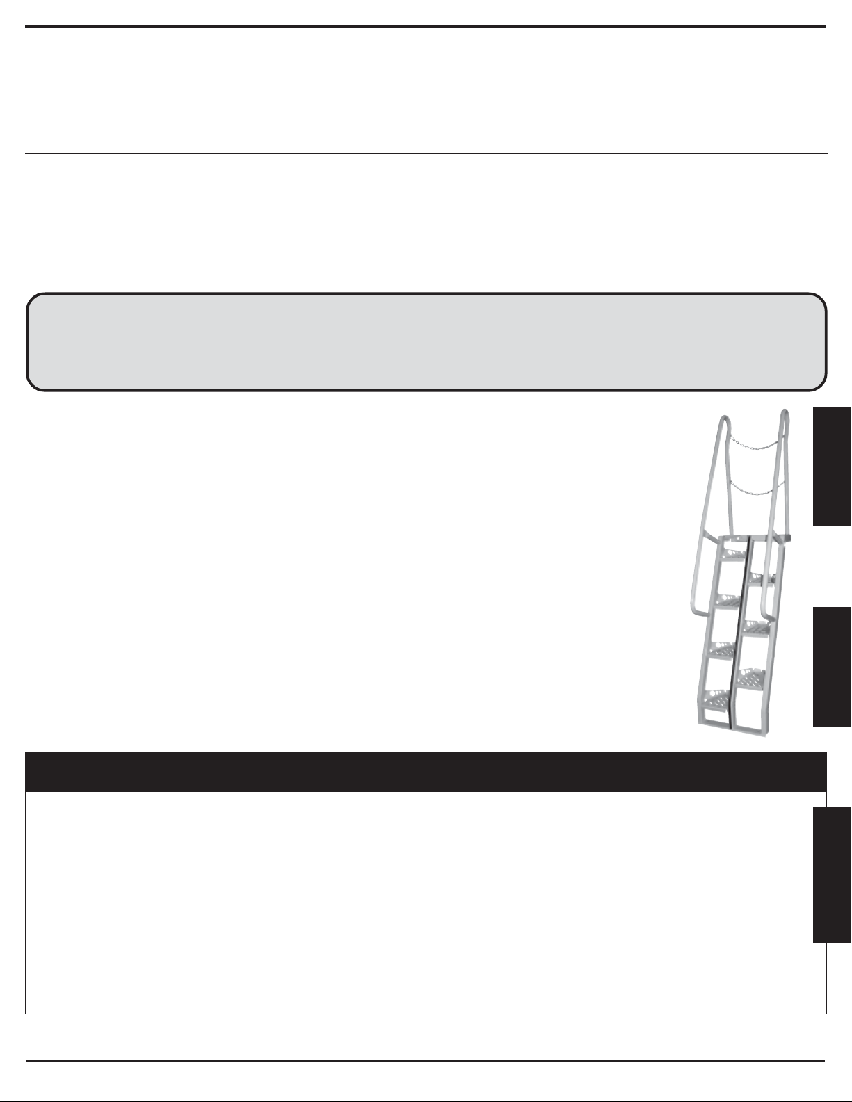
ALTERNATING-TREAD STAIR • Series ATS
Specification Drawing ...........................................2
Assembly/Installation Instructions .........................3
RECEIVING INSTRUCTIONS
Every unit is thoroughly tested and inspected prior to
shipment. However, it is possible that the unit may incur damage
during transit. If damage is noticed when unloading, make a note
of it on the BILL OF LADING. Remove all packing and strapping
material, then inspect the unit again for damage. IF DAMAGE IS
EVIDENT, FILE A CLAIM WITH THE CARRIER
IMMEDIATELY!
WARRANTY
This product is warranted for 90 DAYS from date of purchase to
be free of manufacturing defects in material and workmanship.
This warranty does not cover normal wear of parts or
damage resulting from any of the following: negligent use or
misuse of the product, a use or application contrary to
installation instructions, or the disassembly, repair or alteration
by any person prior to authorization from a factory
representative.
SPECIFICATIONS (for Drawing on Back)
Model
Number
ATS-4-56
ATS-5-56
ATS-6-56
ATS-7-56
ATS-8-56
ATS-9-56
ATS-10-56
ATS-4-68
ATS-5-68
ATS-6-68
ATS-7-68
ATS-8-68
ATS-9-68
ATS-10-68
Number
of Steps
7
8
10
12
13
15
16
6
7
9
10
11
13
14
Height
(A)
48"
60"
72"
84"
96"
108"
120"
48"
60"
72"
84"
96"
108"
120"
Length
(B)
36-5/8"
44-11/16"
52-13/16"
60-7/8"
69"
77-1/16"
85-3/16"
26"
30-13/16"
35-11/16"
40-9/16"
45-3/8"
50-1/4"
55-1/16"
Step Height
(C)
6-7/8"
7-1/2"
7-3/16"
7"
7-3/8"
7-3/16"
7-1/2"
6-7/8"
7-1/2"
7-3/16"
7"
7-3/8"
7-3/16"
7-1/2"
ALTERNATING-TREAD STAIR
Series ATS
Angle
(D)
56°
56°
56°
56°
56°
56°
56°
68°
68°
68°
68°
68°
68°
68°
Handrail
Height (E)
17-3/16"
17-3/16"
17-3/16"
17-3/16"
17-3/16"
17-3/16"
17-3/16"
10-13/16"
10-13/16"
10-13/16"
10-13/16"
10-13/16"
10-13/16"
10-13/16"
Usable Step
Length (F)
9-1/4"
10-1/8"
9-11/16"
9-7/16"
9-15/16"
9-11/16"
10-1/8"
5-9/16"
6-1/16"
5-13/16"
5-11/16"
5-15/16"
5-3/16"
6-1/16"
Bottom Handrail
Height (G)
27-1/2"
27-1/2"
27-1/2"
27-1/2"
27-1/2"
27-1/2"
27-1/2"
34"
34"
34"
34"
34"
34"
34"
E
N
G
L
I
S
H
E
S
P
A
N
O
L
F
R
A
N
Ç
A
I
S
Page 2
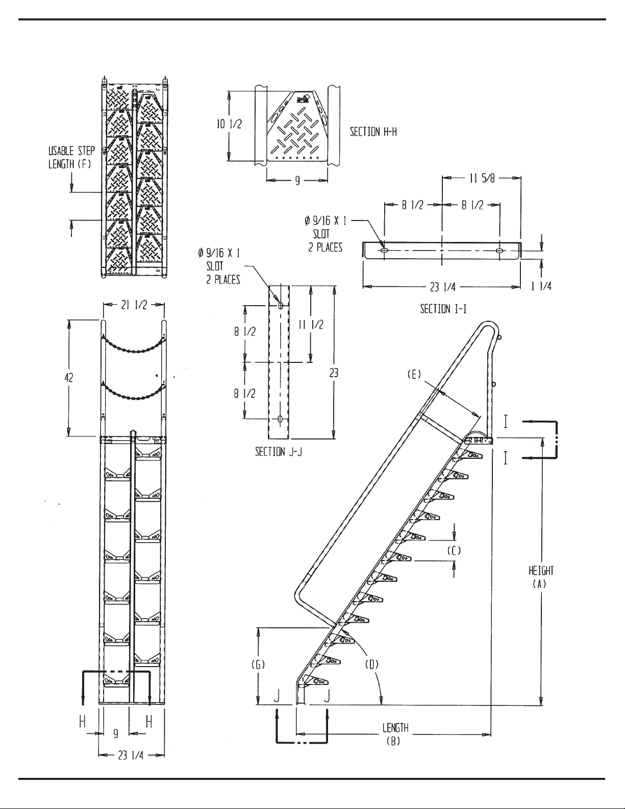
SPECIFICATION DRAWING
Page 3
ASSEMBLY / INSTALLATION INSTRUCTIONS
Review this entire page before installing the stair. Consult
the factory in the event there are any questions or
problems at the time of installation.
¨ The alternating-tread stair is intended for
installations requiring a stair having an angle of
inclination of 56° to 68° to the horizon. It has a
maximum load capacity of 300 pounds.
• Modifications to the stair without prior
manufacturer's authorization may void the
stair's warranty.
• The stair must be appropriately
anchored at the top and bottom
before use.
• The installation must be made so that
it complies with all the building
regulations applicable to the location.
The end-user must verify that the
stair is installed so it will be suited for
the application in which it will be
used.
• Installation must be performed by
suitably trained personnel with
access to the appropriate equipment.
TOOLS FOR INSTALLATION:
1. A fork truck or hoisting means to
unload the lift from the freight truck. It
will also be advantageous to have the
lifting device to help set the stair into
place.
2. Tools and hardware appropriate for
the selected method of installation.
Consult the building's architect or
facility engineer to determine the best
type of hardware with which to anchor
the stair.
ASSEMBLY:
1. Turn the stair on its side.
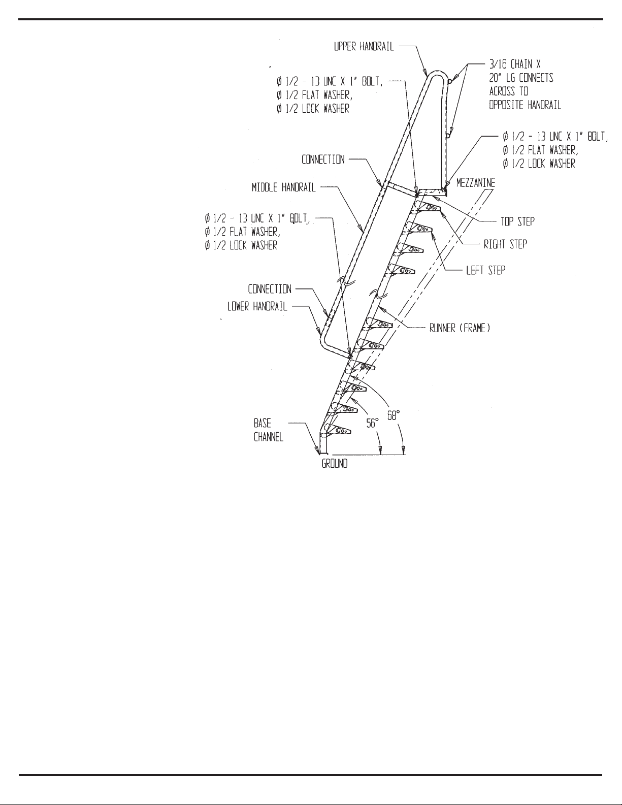
2. Secure the lower handrail (consult the included assembly drawing for identification of the handrails) to the lower end of the tread
runner using a 1/2" flat washer, lock washer, and bolt.
3. Slide the upper handrail onto the lower handrail.
4. Secure the end of the upper handrail and its support bracket using 1/2" flat washers, lock washers, and bolts.
5. Turn the unit on the opposite side and repeat steps 2 - 4.
INSTALLATION:
1. Stand the stair upright, wit the highest step resting against the side of, and the top step even with, the upper floor level.
2. Attach the top of the stair by installing appropriate hardware through the hole and slot located in the edge of the top step.
3.
Warning!
4. Attach the bottom of the stair to the lower floor level using appropriate hardware through the slots in the base channel.
5. Align the bottom and top ends of the stairs so the stair is perpendicular to the wall it is being mounted against, and tighten all
hardware wrench-tight.
6. There are snap hooks on the ends of each of the two included safety chains. Attach one end of each chain to a d-ring on one of
the upper handrail's vertical posts. Attach the other end of each chains to a d-ring on the opposite post. Keep the chains secured
across the top stair opening when the stairs is not being used.
Do not stand on the stair until the installation is complete.
Periodically check that all the stair fasteners are maintained wrench tight.
Page 4

Vestil Manufacturing Corporation
2999 North Wayne St., Angola, IN 46703
Ph: 260-665-7586 • Fax: 260-665-1339
E-mail: sales@vestil.com
Website: www.vestil.com
Contenido
Instrucciones de recibo ........................................ 1
Garantia................................................................ 1
Gráfica de especificaciones ................................. 1
INSTRUCCIONES DE RECIBO
Cada unidad está inspeccionada a fondo y probada
antes del envio. Aun asi, es posible que la unidad se dañe
durante el envio. Si ve algún daño durante la descarga anótelo
en el RECIBO DE ENVIO. Quite todo el material de
empaquetado y las correas, inspeccione por daños. SI HAY
DAÑOS EVIDENTES, ARCHIVE UNA RECLAMACION CON EL
TRANSPORTISTA IMMEDIATAMENTE.
Revisado 01-05
Una compañia dedicada a resolver problemas ergonómicos
y de manejo del material desde 1955.
MANUAL DEL
PROPIETARIO
ESCALERA DE PELDAÑOS ALTERNATIVOS
Dibujos de especificaciones .................................2
Instrucciones de instalación ..................................3
GARANTIA
Este producto está garantizado durante 90 DIAS desde la
fecha de compra de estar libre de defectos de material y mano de obra.
Esta garantia no cubre el gasto normal de partes o daños
que resulten de lo siguiente: uso negligente o mal uso del producto,
uso o aplicación contraria a las instrucciones de instalación, o
desensamble, reparaciones o alteraciones por cualquier persona
antes de la previa autorización de un representante de la fábrica.
ESPECIFICACIONS (Para el dibejo en el reverso)
Número
de modelo
ATS-4-56
ATS-5-56
ATS-6-56
ATS-7-56
ATS-8-56
ATS-9-56
ATS-10-56
ATS-4-68
ATS-5-68
ATS-6-68
ATS-7-68
ATS-8-68
ATS-9-68
ATS-10-68
Número de
escalones
7
8
10
12
13
15
16
6
7
9
10
11
13
14
Altura
(A)
48"
60"
72"
84"
96"
108"
120"
48"
60"
72"
84"
96"
108"
120"
Largo
(B)
36-5/8"
44-11/16"
52-13/16"
60-7/8"
69"
77-1/16"
85-3/16"
26"
30-13/16"
35-11/16"
40-9/16"
45-3/8"
50-1/4"
55-1/16"
Altura del
escalón (C)
6-7/8"
7-1/2"
7-3/16"
7"
7-3/8"
7-3/16"
7-1/2"
6-7/8"
7-1/2"
7-3/16"
7"
7-3/8"
7-3/16"
7-1/2"
ESCALERA DE PELDAÑOS
ALTERNATIVOS
Series ATS
Ángulo
(D)
56°
56°
56°
56°
56°
56°
56°
68°
68°
68°
68°
68°
68°
68°
Altura de la
barandilla (E)
17-3/16"
17-3/16"
17-3/16"
17-3/16"
17-3/16"
17-3/16"
17-3/16"
10-13/16"
10-13/16"
10-13/16"
10-13/16"
10-13/16"
10-13/16"
10-13/16"
Largo de la
parte usable del
escalón (F)
9-1/4"
10-1/8"
9-11/16"
9-7/16"
9-15/16"
9-11/16"
10-1/8"
5-9/16"
6-1/16"
5-13/16"
5-11/16"
5-15/16"
5-3/16"
6-1/16"
E
S
P
A
N
O
L
Altura de la
barandilla
inferior (G)
27-1/2"
27-1/2"
27-1/2"
27-1/2"
27-1/2"
27-1/2"
27-1/2"
34"
34"
34"
34"
34"
34"
34"
Page 5

DIBUJO DE ESPECIFICATIONES
Page 6

ENSAMBLE E INSTRUCCIONES DE INSTALACIÓN
Revise est página completamente antes de instalar la escalera.
Consulte con el fabricante en caso de que tenga preguantas o
problemas al momento de la instalación.
¨ La escalera de peldaños alternativos está intencionada
para instalaciones que requieran una escalera con un
ángulo de inclinación de 56" a 68" hacia el horizonte.
Tiene una capacidad máxima de 300 libras.
• Modificaciones de la escalera sin la autorización
previa del fabricante podria anular la garantía de la
escalera.
• La escalera debe de estar correctamente
anclada al extremo superior e iferior antes del
uso.
• La instalación debe de ser de tal manera que
cumpla con todas las regulaciones del edificio
que sean aplicables a ese lugar. El usuario
debe verificar que la escalera está instalada de
manera que pueda ser compatible con la
aplicación con la que se va a usar.
• La instalación se debe hacer por personal
entrenado y calificado con acceso al equipo
necesario.
1/2 - 13 UNC X 1" BOLT
1/2 - ARANDÉLA PLANA
1/2 ARANDELA DE CIERRE
BARANDILLA
INFERIOR
BARANDILLA
SUPERIOR
1/2 - 13 UNC X 1" BOLT
1/2 - ARANDÉLA PLANA
1/2 ARANDELA DE CIERRE
CONEXIÓN
3/16 CADENA X 18"
LG. CONECTA HASTA
LA BARANDILLA
OPUESTA
1/2 - 13 UNC X 1" BOLT
1/2 - ARANDÉLA PLANA
1/2 ARANDELA DE CIERRE
ESCALÓN SUPERIOR
ESCALÓN DERECHO
ESCALÓN IZQUIERDO
ARMAZÓN
HERRAMIENTAS DE INSTALACIÓN:
1. Una transpaleta or grúa para descargar el
elevador del camión. También tendra ventajas
el tener una maquinaria de elevación para
ayudar a poner la escalera en su lugar.
2. Herramientas y ferreterías para el método
selecto de instalación. Consulte con el
CANEL
DE BASE
arquitecto del edificio o con el ingeniero del
lugar para determinar la mejor ferreteria con la
SUELO
que anclar la escalera.
ENSAMBLE:
1. Gire la escalera a su lateral.
2. Asegure la barandilla inferior (consulte los dibujos de ensamble incluidos para la identificación de las barandillas) al extremo
inferior del peldaño usando una arandela plana del 1/2", una arandela de cierre y un tornillo.
3. Deslice la barandilla superior a la barandilla inferior.
4. Asegure el extremo de la barandilla superior a la repisa de soporte usando arandelas planas de 1/2", atandelas de cierre, y
tornillos.
5. Gir la unidad hacia la posición opuesta y repita los pasos 2-4.
INSTALACIÓN:
1. Ponga la escalera en la posición derecha, ponga el escalón más alto descansando contra el lado, y el escalón superior a nivel
con el piso superior.
2. Asegure el extremo superior de la escalera instalando la ferreteria a través del agujero localizado en el extremo del escalón
superior.
3.
Aviso!
No se ponga en la escalera hasta que la instalación este completa.
4. Asegure el extremo inferior de la escalera al piso de abajo usando la ferreteria adecuada a través de los agujeros en la base del
canal.
5. Alinie los extremos inferior y superior de la escalera para que la escalera esté perpendicular a la pared a la que se va a montar, y
apriete toda la ferreteria con una llave.
6. Hay unos ganchos de cierre en los extremos de cada una de las dos cadenas de seguridad incluidas. Asegure un extremo de
cada cadena a la anilla de d y a un extremo a los postes verticales de la barandilla superior. Asegure el otro extremo de cada
cadena a la anilla de d en el poste opuesto. Mantenga las cadenas aseguradas a través de la abertura superior de la escalera
cuando la escalera no este en uso.
Compruebe periodicamente que todos los seguros de la escalera están apretados.
Page 7

Vestil Manufacturing Corporation
2999 North Wayne St., Angola, IN 46703
Ph: 260-665-7586 • Fax: 260-665-1339
E-mail: sales@vestil.com
Website: www.vestil.com
Table des Matières
Instructions pour réception ................................... 1
Garantie................................................................ 1
Table de spécifications ........................................ 1
INSTRUCTIONS POUR RÉCEPTION
Chaque unité est soigneusement calibrée et inspectée
avant expédition. Néanmoins, il est possible que l'unité puisse être
endommagée pendant transport. Si vous voyez des dommages
pendant le déchargement, notex-les sur le CONNAISSEMENT.
Enlever toute matière d'emballage ou de cerclage et inspecter
encore pour des dommages. SI DES DOMMAGES SONT
EVIDENTS, DÉPOSER UN RÉCLAMATION AVEC LE
TRANSPORTEUR IMMÉDIATEMENT!
GARANTIE
Ce produit est garanti pendant 90 JOURS après la date d'achat
d'être sans défauts de manufacture en matières ou en construction.
Cette garantie ne comprend pas l'usure normale des pièces ou des
dommages résultant des actions suivantes: utilisation négligente
ou abus du produit, utilisation ou application contraire aux instructions
d'installation ou démontage, réparations ou altérations par toute
personne avant d'obtenir l'autorisation d'un reprentant de l'usine.
Revised 01-05
A company dedicated to solving ergonomic
and material handling problems since 1955.
GUIDE
D'UTILISATION
ÉCHELLE À GIRON ALTERNANT • série ATS
Dessin de spécifications .......................................2
Instructions pour installation ..................................3
ÉCHELLE À GIRON
ALTERNANT
série ATS
SPECIFICATIONS (pour dessin)
Modèle
ATS-4-56
ATS-5-56
ATS-6-56
ATS-7-56
ATS-8-56
ATS-9-56
ATS-10-56
ATS-4-68
ATS-5-68
ATS-6-68
ATS-7-68
ATS-8-68
ATS-9-68
ATS-10-68
Nombre de
marches
7
8
10
12
13
15
16
6
7
9
10
11
13
14
Hauteur
(A)
48"
60"
72"
84"
96"
108"
120"
48"
60"
72"
84"
96"
108"
120"
Longueur
(B)
36-5/8"
44-11/16"
52-13/16"
60-7/8"
69"
77-1/16"
85-3/16"
26"
30-13/16"
35-11/16"
40-9/16"
45-3/8"
50-1/4"
55-1/16"
Hauteur de
marche (C)
6-7/8"
7-1/2"
7-3/16"
7"
7-3/8"
7-3/16"
7-1/2"
6-7/8"
7-1/2"
7-3/16"
7"
7-3/8"
7-3/16"
7-1/2"
Angle
(D)
56°
56°
56°
56°
56°
56°
56°
68°
68°
68°
68°
68°
68°
68°
Hauteur
de main
courante (E)
17-3/16"
17-3/16"
17-3/16"
17-3/16"
17-3/16"
17-3/16"
17-3/16"
10-13/16"
10-13/16"
10-13/16"
10-13/16"
10-13/16"
10-13/16"
10-13/16"
Longueur
de marche
disponible (F)
9-1/4"
10-1/8"
9-11/16"
9-7/16"
9-15/16"
9-11/16"
10-1/8"
5-9/16"
6-1/16"
5-13/16"
5-11/16"
5-15/16"
5-3/16"
6-1/16"
Hauteur de
bas de main
courante (G)
27-1/2"
27-1/2"
27-1/2"
27-1/2"
27-1/2"
27-1/2"
27-1/2"
34"
34"
34"
34"
34"
34"
34"
F
R
A
N
Ç
A
I
S
Page 8

LONGUEUR DE
MARCHE
DISPONIBLE (F)
SPECIFICATION DRAWING
FENTE
FENTE
LONGUEUR
HAUTEUR
Page 9

ASSEMBLAGE / INSTRUCTIONS D'INSTALLATION
Relire cette page entière avant d'installer léchelle. Consulter l'usine s'il
y a des questions ou des problèmes au temps d'installation.
¨ L'escalier au giron alternant est destiné pour des
installations ayant besoin d'un escalier avec un angle
d'inclinaison de 56° à l'horizon. Il a une capacité de
charge maximum de 300 livres (136 kg).
• Des modifications à l'escalier sans l'autorisation du
fabricant peuvent invalider la garantie de l'escalier.
• L'escalier doit être convenablement ancré par le haut
er en bas avant utilisation.
• L'installation doit être effectuée pour qu'elle
satisfasse toutes les régulations de
construction applicables à l'emplacement.
L'utilisateur final doit vérifier que l'escalier est
installé pour qu'il soit convenable pour
l'application dans laquille il sera utilisé.
• Installation doit être effctuée par un personnel
instruit avec de léquipement approprié.
OUTILS POUR INSTALLATION:
1. Un chariot élévateiur à fourche ou autre
disposifif de levage pour décharger l'élévateur
du camion de transport. Il sera aussi
avantageux d'avoir le dispositif de levage pour
aider à mettre l'escalier en place.
2. Des outils et des ferrures nécessaires et
convenables pour la méthode d'installation
choisie. Consulter l'architecte du bâtiment ou
l'ingénieur pour déterminer les meilleures
ferrures avec lesquelles d'ancrer l'escalier!
1/2 - 13 UNC X 1" BOULON
1/2 RONDELLE PLATE
1/2 RONDELLE FREIN
PIÈCE
INTERMÉDIAIRE
MAIN COURANT
INFÉRIEURE
MAIN
COURANTE
RAINURE
DE BASE
MAIN COURANTE
SUPÉRICURE
1/2 - 13 UNC X 1" BOULON
1/2 RONDELLE PLATE
1/2 RONDELLE FREIN
PIÈCE
INTERMÉDIAIRE
CHAINE 3/16 X 18 LONG
AVEC CONNEXION Á LA
MAIN COURANTE EN FACE
1/2 - 13 UNC X 1" BOULON
1/2 RONDELLE PLATE
1/2 RONDELLE FREIN
MEZZANIE
MARCHE SUPÉRIEURE
MARCHE À DROITE
MARCHE À GAUCHE
MONTANT (CHASSIS)
ASSEMBLAGE:
1. Mettre l'escalier sur un de ses cotés.
SOL
2. Attacher la main courante inférieure (consulter le
dessin d'assemblage ici pour l'identification des
mains courantes) au bout inférieur du cadre-support en utilisant une rondelle plate d'1/2 pouce, une rondelle frein et un boulon.
3. Glisser la main courante supérieure sur la main courante inférieure.
4. Attacher la bout de la main courante supérieure et son support en utilisant des rondelles plates 1/2, des roundelles frein et des
boulons.
5. Retourner l'unité sur son coté opposé et répéter les instructions 2 à 2 ici.
INSTALLATION:
1. Lever l'escalier verticalement avec la marche la plus haute inclinant contre le coté de et au miveau de l'étage supérieur.
2. Attacher le haut de l'escalier un insérant des ferrures appropriées à travers le trou et la fente situés au bord de la marche
supérieure.
3.
Attention!
Ne vous mettez pas sur l'escalier avant que l'installation soit finie!
4. Attacher le bas de l'escalier ou sol du niveau inférieur en insérieur en insérant des ferrures appropriées par les fentes dans la
gorge de base.
5. Aligner les bouts inférieurs et supérieurs des escaliers pour que l'escalier soit perpendiculaire au mur contre lequel il est installé
et serrer fort toutes les ferrures avec une clé.
6. Il y a des mousquetons sur les bouts de chacune des deux chaînes de sécurité. Attacher un bout de chaque chaîne à un anneau
ne D sur un des montants verticaux de la main courante supérieure. Attacher l'autre bout de chaque chaîne à un anneau en D sur
le montant en face. Garder les chaînes attachées à travers l'ouverture en haut de l'escalier quand lescalier n'est pas en train
d'être utilisée.
Vérifier périodiquement que toutes les attaches de l'escalier sont serrées aussi fort que possible avec une clé.
 Loading...