

Page 1
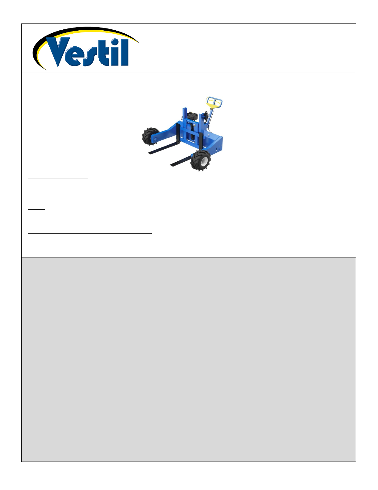
Table of Contents Rev. 2/28/2020 ALL-T-2/4-GPT MANUAL
Vestil Manufacturing Corp.
Table of Contents
ALL-T-(2 or 4)-GPT
ALL-T-(2 or 4)-GPT-PT
ALL-T-(2 or 4)-GPT-L
ALL-T-(2 or 4)-GPT-10HP
ALL-T-(2 or 4)-GPT-L-10HP
Receiving instructions:
After delivery, remove the packaging from the product. Inspect the product closely to determine whether it
sustained damage during transport. If damage is discovered, record a complete description of it on the bill of lading. If
the product is undamaged, discard the packaging.
NOTE:
The end-user is solely responsible for confirming that product design, use, and maintenance comply with laws,
regulations, codes, and mandatory standards applied where the product is used.
Replacement Parts and Technical Assistance:
If you have questions that are not addressed in these instructions and to order replacement parts, labels, and
accessories, call (260) 665-7586 and ask for the Service and Parts Department. The department can also be
contacted online at http://www.vestilmfg.com/parts_info.htm.
Specifications…………………...…………................................................................................................................... 2, 3
Applicable National Standards…………………………………………………………………………………………………4
Signal Words……….……………….............................................................................................................................. 4
Safety Instructions.................................................................................................................................................... 4
Operating the Truck…………………….………............................................................................................................ 5
Fork Carriage Controls……...……………………………………………………………………………………................... 5 - 6
Lifting and Transporting Loads………….……………………………………………………………………………………. 6
Parking Brake………………………………................................................................................................................... 7
Disengaging the Transmission (Neutral Mode)...…………………………………………………………………………… 7
Record of Satisfactory Condition……………………………………………………………………………………………… 7
Inspections and Maintenance…………………………………………………………………………………………………. 7 - 8
Complete Exploded Views & Bill of Materials………………………………………………………………………………..9 - 16
ALL-T-2-GPT; ALL-T-4-GPT; ALL-T-2-GPT-L; & ALL-T-4-GPT-L…………………………………………………….. 9 - 10
ALL-T-2-GPT-10HP; ALL-T-4-GPT-10HP; ALL-T-2-GPT-L-10HP; & ALL-T-4-GPT-L-10HP…………................... 11-12
ALL-T-2-GPT-PT; ALL-T-4-GPT-PT; ALL-T-2-GPT-L-PT; & ALL-T-4-GPT-L-PT…………………………………… 13-14
ALL-T-2-GPT-PT-10HP; ALL-T-4-GPT-PT-10HP; ALL-T-2-GPT-L-PT-10HP; & ALL-T-4-GPT-L-PT-10HP…….. 15-16
Rear Wheel Axle Assemblies (1) and (2) Exploded Views and Bills of Materials………………………..……………... 17
Steering Handle Subassembly Exploded View and Bill of Materials……………………………………………………... 18
Power Unit Subassembly Exploded Views and Bills of Materials…………………………………………………………. 19-22
ALL-T-2-GPT & ALL-T-4-GPT…………………………………………………………………………………………….. 19
ALL-T-2-GPT-10HP; ALL-T-4-GPT-10HP; ALL-T-2-GPT-L-10HP; & ALL-T-4-GPT-L-10HP………………………. 20
ALL-T-2-GPT-PT; ALL-T-4-GPT-PT; ALL-T-2-GPT-L-PT; & ALL-T-4-GPT-L-PT…………………………………… 21
ALL-T-2-GPT-PT-10HP; ALL-T-4-GPT-PT-10HP; ALL-T-2-GPT-L-PT-10HP; & ALL-T-4-GPT-L-PT-10HP…….. 22
Sprocket Drive Subassemblies, Right Side, Exploded Views and Bills of Materials……………………………………. 23
Sprocket Drive, Subassemblies, Left Side, Exploded Views and Bills of Materials..…………………………………… 24
Labeling Diagram…….……………………………………………………………………………………………………..….. 25
Limited Warranty……………………………………………………………………………………………………………….. 26
2999 North Wayne Street, P.O. Box 507, Angola, IN 46703
Telephone: (260) 665-7586 -or- Toll Free (800) 348-0868
http://www.vestilmfg.com/ e-mail: info@vestil.com
All Terrain Pallet Truck
Instruction Manual
Fax: (260) 665-1339
ALL-T-(2 or 4)-GPT-L-PT
ALL-T-(2 or 4)-GPT-PT-10HP
ALL-T-(2 or 4)-GPT-L-PT-10HP
Table of Contents Copyright 2019 Vestil Manufacturing Corp. Page 1 of 26
Page 2
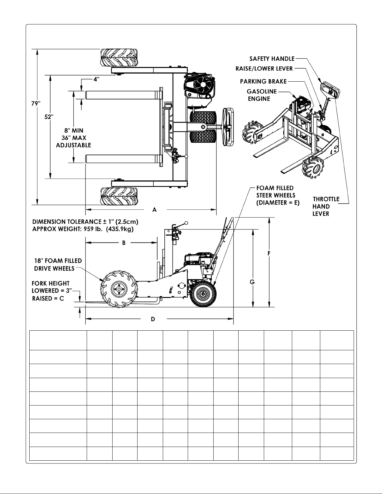
Table of Contents 2/28/2020 ALL-T-2/4-GPT MANUAL
13” to 24”
(33.0cm to 61.0cm)
12,000 lb.
(5,454.5 kg)
1,000 lb.
(454.5kg)
549 lb.
(249.5 kg)
Engine
ment
653/4”
167cm
36”
91.4cm
12”
30.5cm
745/16”
188.8cm
13”
33.0cm
451/8”
114.6cm
391/16”
99.2cm
953 lb.
433.2kg
2000 lb.
909.1kg
7011/16”
179.5cm
36”
91.4cm
12”
30.5cm
7713/16”
197.6cm
16”
40.6cm
483/8”
122.9cm
395/16”
99.9cm
1051 lb.
477.7kg
2000 lb.
909.1kg
773/4”
197.5cm
48”
121.9cm
12”
30.5cm
865/16”
219.2cm
13”
33.0cm
453/8”
115.3cm
395/16”
99.9cm
997 lb.
453.2kg
2000 lb.
909.1kg
8211/16”
210.0cm
48”
121.9cm
12”
30.5cm
8913/16”
228.1cm
16”
40.6cm
489/16”
123.3cm
397/16”
100.2cm
1094 lb.
497.3kg
2000 lb.
909.1kg
661/2”
168.9cm
36”
91.4cm
12”
30.5cm
751/16”
190.7cm
13”
33.0cm
453/8”
115.3cm
395/16”
99.9cm
1012 lb.
460kg
4000 lb.
1818.2kg
717/16”
181.5cm
36”
91.4cm
12”
30.5cm
789/16”
199.5cm
16”
40.6cm
481/2”
123.2cm
395/16”
99.9cm
1056 lb.
480kg
4000 lb.
1818.2kg
781/2”
199.4cm
48”
121.9cm
12”
30.5cm
871/16”
221.1cm
13”
33.0cm
453/8”
115.3cm
395/16”
99.9cm
1065 lb.
484.1kg
4000 lb.
1818.2kg
837/16”
211.9cm
48”
121.9cm
12”
30.5cm
909/16”
230.0cm
16”
40.6cm
481/2”
123.2cm
395/16”
99.9cm
1162 lb.
528.2kg
4000 lb.
1818.2kg
SPECIFICATIONS: UNITS WITHOUT POWERED TILT
Dimensions, capacity, net weight, and other attributes appear in the diagrams and table below.
Model
PMT-GPT
Service Range of
Ball Hitch
Uniform Pulling
Capacity
Hitch Lifting Capacity
(Max. Tongue Weight)
Net Weight
Model A B C D E F G
ALL-T-2-GPT
ALL-T-2-GPT-10HP
ALL-T-2-GPT-L
ALL-T-2-GPT-L-10HP
ALL-T-4-GPT
ALL-T-4-GPT-10HP
ALL-T-4-GPT-L
ALL-T-4-GPT-L-10HP
Net
weight
Table of Contents Copyright 2019 Vestil Manufacturing Corp. Page 2 of 26
Capacity
displace-
190cc
344cc
190cc
344cc
190cc
344cc
190cc
344cc
Page 3
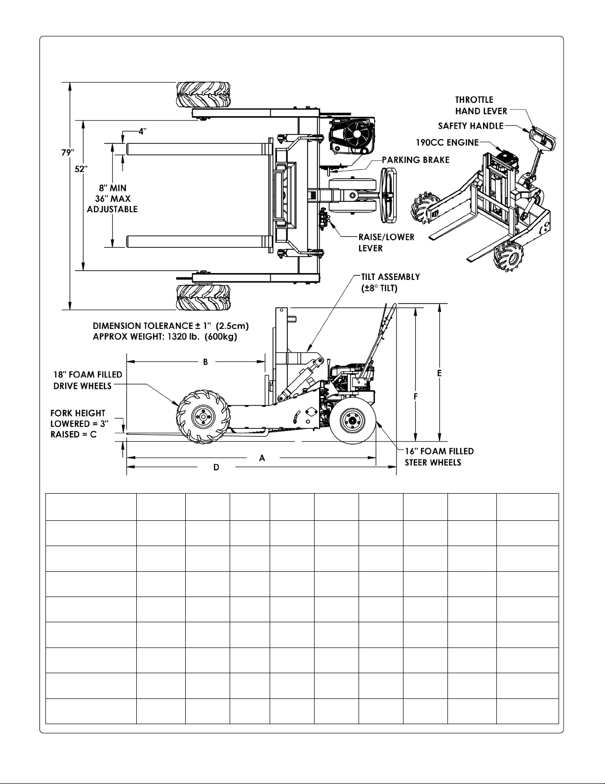
Table of Contents 2/28/2020 ALL-T-2/4-GPT MANUAL
189.2cm
91.4cm
50.8cm
207.2cm
121.1cm
117.5cm
575kg
909.1kg
219.7cm
121.9cm
50.8cm
237.6cm
121.1cm
117.5cm
585.9kg
909.1kg
219.7cm
121.9cm
50.8cm
237.6cm
121.1cm
117.2cm
601.8kg
909.1kg
221.5cm
121.9cm
50.8cm
239.6cm
119.9cm
117.5cm
620.9kg
1818.2kg
SPECIFICATIONS: UNITS WITH POWERED TILT (“-PT” IN MODEL NAME)
Dimensions, capacity, net weight, and other attributes appear in the diagrams and table below.
Model A B C D E F
ALL-T-2-GPT-PT
ALL-T-2-GPT-PT-
10HP
ALL-T-2-GPT-L-PT
ALL-T-2-GPT-L-PT-
10HP
ALL-T-4-GPT-PT
ALL-T-4-GPT-PT-
10HP
ALL-T-4-GPT-L-PT
ALL-T-4-GPT-L-PT-
10HP
Table of Contents Copyright 2019 Vestil Manufacturing Corp. Page 3 of 26
741/2”
741/2”
189.2cm
861/2”
861/2”
753/16”
191.0cm
753/16”
185.9cm
873/16”
873/16”
221.5cm
36”
36”
91.4cm
48”
48”
36”
91.4cm
36”
91.4cm
48”
48”
121.9cm
20”
20”
50.8cm
20”
20”
20”
50.8cm
20”
50.8cm
20”
20”
50.8cm
819/16”
819/16”
207.2cm
939/16”
939/16”
825/16”
209.1cm
825/16”
209.1cm
945/16”
945/16”
239.6cm
4711/16”
4711/16”
121.1cm
4711/16”
4711/16”
473/16”
119.9cm
471/8”
199.7cm
473/16”
471/8”
119.7cm
461/4”
461/8”
117.2cm
461/4”
461/8”
461/4”
117.5cm
461/8”
117.2cm
461/4”
461/8”
117.2cm
Net
weight
1265 lb.
1300 lb.
590.9kg
1289 lb.
1324 lb.
1332 lb.
605.5kg
1367 lb.
621.4kg
1366 lb.
1401 lb.
636.8kg
Capacity
2000 lb.
2000 lb.
909.1kg
2000 lb.
2000 lb.
4000 lb.
1818.2kg
4000 lb.
1818.2kg
4000 lb.
4000 lb.
1818.2kg
Engine
displacement
190cc
344cc
190cc
344cc
190cc
344cc
190cc
344cc
Page 4

Table of Contents 2/28/2020 ALL-T-2/4-GPT MANUAL
APPLICABLE NATIONAL STANDARDS
This product is a rough terrain lift truck. The Industrial Truck Standards Development Foundation (ITSDF)
publishes national standard ANSI/ITSDF B56.6 (the “Standard”) on its website (www.itsdf.org
). The standard is freely
downloadable at http://www.itsdf.org/cue/b56-standards.html. Before putting your pallet truck into service, acquire a
copy of the Standard and apply all recommendations in Part II: For the User. If instructions provided in this manual
conflicts with instructions in the Standard, then you should apply the instructions in the Standard.
SIGNAL WORDS
This manual uses SIGNAL WORDS to direct the reader’s attention to important safety-related messages.
These messages describe uses of the product that could result in personal injury or property damage. Each
signal word corresponds to a specific hazard level. The following are definitions of signal words that might
appear in this manual.
Identifies a hazardous situation which, if not avoided, WILL result in DEATH or
SERIOUS INJURY. Use of this signal word is limited to the most extreme situations.
Identifies a hazardous situation which, if not avoided, COULD result in DEATH or
SERIOUS INJURY.
Indicates a hazardous situation which, if not avoided, COULD result in MINOR or
MODERATE injury
Identifies practices likely to result in product/property damage, such as operation that
might damage the product.
.
SAFETY INSTRUCTIONS
Vestil strives to identify all foreseeable hazards associated with the use of its products. However, material
handling is dangerous and no manual can address every risk. Ultimately the most effective way to prevent
injury is for the operator to apply sound judgment whenever using this device.
Improper or careless operation of this device might result in serious personal injuries.
• Read and understand this entire manual before using or servicing this pallet truck. Read the manual
whenever necessary to refresh your understanding of proper operation and maintenance procedures. An instruction
manual for the gasoline motor is provided with this unit. Read the entire manual before operating the truck for the
first time.
• DO NOT exceed the capacity of your unit. Capacity information is provided in the Specifications tables on pages 2
& 3. The truck is also labeled with its capacity. See label 287 in Labeling Diagram on p. 25.
• Inspect the truck as directed in Inspections and Maintenance on pages 5-6. DO NOT use the device unless it is in
satisfactory condition. See Record of Satisfactory Condition on p. 7.
• NEVER park the truck on sloped terrain. Only park on level ground. Always apply the parking brake whenever the
truck is stopped.
• Only use this product to lift and move palletized loads.
• Completely engage loads with forks. Fork length should be at least two-thirds of length of the parallel dimension
of the pallet.
• DO NOT allow people to ride on the truck or the load.
• Ascend and descend grades slowly. Do not traverse grades of more than 7%. The forks should only be raised as
far as necessary to clear the road surface. Travel straight up and down the grade, i.e. avoid turning on grades. If
your pallet truck is equipped with the powered tilt feature (-PT in model name), make sure that the carriage is not
tilted forward whenever crossing grades. Traverse grades with the forks downgrade from you.
• If the load obstructs forward view, travel with the load trailing.
• Any load applied to the forks must be centered and evenly distributed on a pallet.
• Only use the truck if you are familiar with the controls. Start, stop, turn, and reverse directions smoothly to shifting
the load. Sudden shifting could cause the load and truck to overturn.
• Reduce speed during turns. Turn slowly and carefully.
• Avoid running over loose objects on the roadway surface.
• DO NOT modify the truck in any way without express, written approval from Vestil. Unapproved modifications
automatically void the Limited Warranty on p. 26 and might make the product unsafe to use.
• DO NOT use this product UNLESS every label shown in the Labeling diagram on p. 25 is in place, undamaged,
and easily readable.
Table of Contents Copyright 2019 Vestil Manufacturing Corp. Page 4 of 26
Page 5
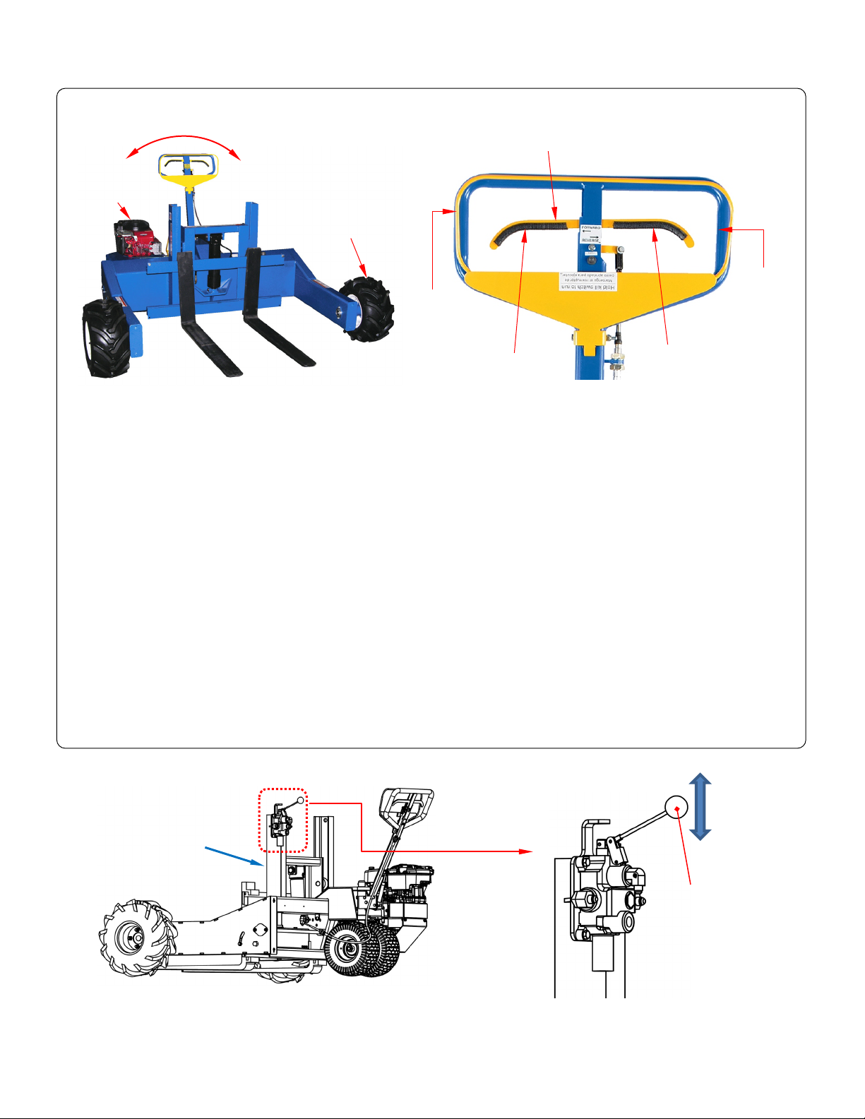
Table of Contents 2/28/2020 ALL-T-2/4-GPT MANUAL
Forward
Reverse
Kill switch
Handle
(blue)
Direction control lever
Drive wheel
Fork
Fork carriage
Handle
Motor
Lower
carriage
Raise
carriage
OPERATING THE TRUCK
assembly
(yellow)
Startup procedure
1. Find the choke and throttle controls for the motor. Apply the engine startup procedure in the motor manufacturer’s
instruction manual.
2. Squeeze the kill switch against the handle with one hand. Pull the engine starter cord with the other hand.
3. After the engine starts, set the choke switch to the open position and allow the engine to warm up for a few
minutes.
4. Set the engine throttle to the desired speed: increasing the throttle increases the speed and vice versa.
Propulsion (Driving the Truck)
a. To move forward, squeeze the right side of the direction control lever towards the top of the handle. The further the
lever is moved the faster the unit moves. Release the lever to stop.
b. To move in reverse, squeeze the left side of the lever towards the top of the handle.
c. Practice shifting between forward and reverse.
NOTE: Do not quickly shift from forward to reverse or vice versa. Sudden shifts can damage the transaxle.
d. When moving heavy loads, i.e. loads close to the unit’s capacity, drive slowly. Driving slowly decreases the load on
the engine.
Steering
Steer the unit by swinging the handle to one side or the other. While turning, the rpm’s of the outer drive wheel
increase and the rpm’s of the inner drive wheel decrease. When turning sharply in one direction or the other, the
difference between rpm’s of the wheels is greater (i.e. the outer wheel turns much faster than the inner wheel).
FORK CARRIAGE CONTROLS
A. Raising and lowering the carriage
1. Raise the forks: (continues on following page)
a. Grasp the knob of the fork carriage control lever and push it forward i.e. away from you/towards the truck.
The hydraulic cylinder extends and causes the carriage to rise.
carriage
control
lever
Table of Contents Copyright 2019 Vestil Manufacturing Corp. Page 5 of 26
Page 6
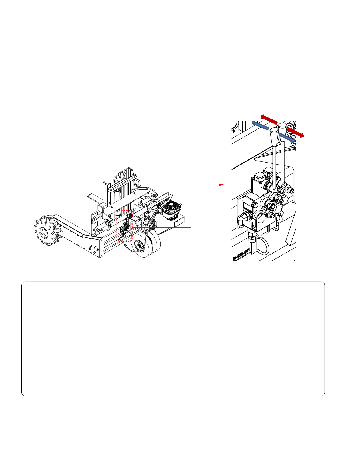
Table of Contents 2/28/2020 ALL-T-2/4-GPT MANUAL
LIFTING AND TRANSPORTING LOADS
Lower
Raise
Tilt
Level
b. Releasing the lever causes to cylinder to stop extending. The cylinder maintains position wherever it stops.
Release the control lever as soon as the desired load elevation is achieved.
NOTE: Do not continue to hold the control lever when the cylinder is completely extended. The hydraulic
fluid could overheat and cause permanent damage to the hydraulic system.
2. Lower the fork carriage: The engine does not have to be running to lower the carriage.
a. Pull the control lever towards you.
b. The carriage descends at a controlled speed. Releasing the lever causes the carriage to stop. It maintains
position wherever it stops. Lowering speed is adjustable. However, the lowering speed is optimized at the
factory. Do not change the lowering speed without approval from, and guidance by, Technical Service.
If the carriage lowers too quickly, a safety device in the cylinder, called a velocity fuse, closes. When the
fuse is closed, hydraulic fluid cannot flow from the cylinder to the reservoir. The cylinder cannot retract and
the carriage does not lower. If this happens, you must reset the velocity fuse by raising the hitch.
B. Tilting the carriage
Units equipped with the powered tilt feature (“-PT” appears in the
model designation) have two control levers.
1. The lever on the left controls up-and-down movement.
2. The lever on the left controls carriage tilt.
a. Push the lever forward to activate a second cylinder. This
cylinder pushes the top of the carriage forward, which
causes the fork tips to drop.
b. Pull back the lever to raise the tips and level the forks.
Before engaging the load:
1. Release the direction control lever.
2. Adjust the engine throttle to mid-speed.
3. Align the forks (on the carriage) with the fork channels in the pallet. The forks must be centered on the carriage.
4. Adjust the elevation of the forks with the Raise/Lower lever.
Mount the pallet on the forks:
1. Drive forward and insert the forks through the pallet. Insert the forks all-the-way. Fork length should be at least 2/3’s
of the parallel dimension of the pallet.
2. Raise the forks to elevate the pallet a few inches above the ground. Do not raise the forks any higher than
necessary.
3. Drive the load to the desired location. Instructions for driving and steering the truck are provided in Operating the
Truck on p. 5.
4. Set the pallet on the ground by lowering the forks. When the pallet rests on the ground, extract the forks from the
pallet by driving the truck in reverse.
Table of Contents Copyright 2019 Vestil Manufacturing Corp. Page 6 of 26
Page 7
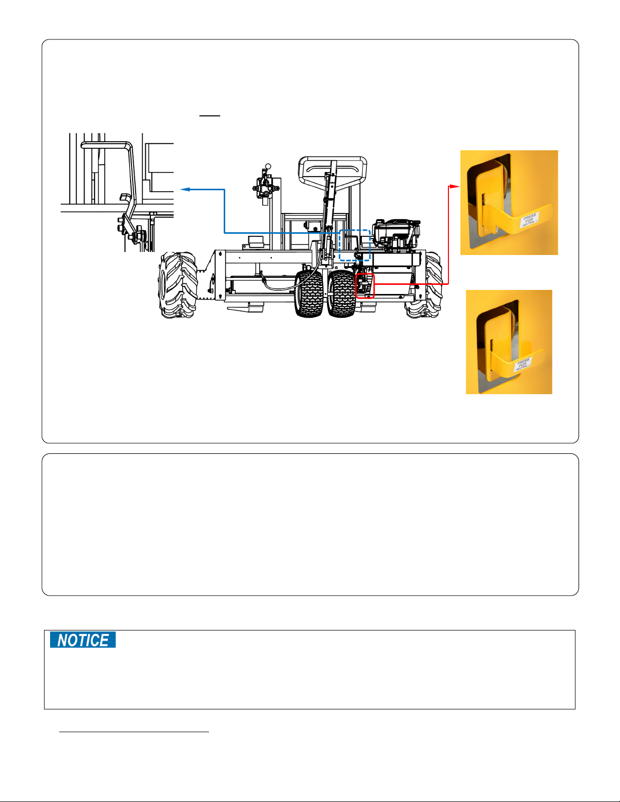
Table of Contents 2/28/2020 ALL-T-2/4-GPT MANUAL
Parking brake lever
Transaxle release lever
PARKING BRAKE
This product is equipped with a parking brake. This brake should only be applied when the unit is stopped. Do not
use the parking brake to slow the unit.
1. To apply the brake pull the brake lever up until it locks.
2. To release the brake, push the lever downward.
NOTE: ONLY park the mover on level ground.
Unload the hydraulic system when you are finished using the truck by lowering the
carriage all the way.
Drive mode: axle engaged
Neutral mode: axle
disengaged
DISENGAGING THE TRANSMISSION (NEUTRAL MODE)
The unit can be moved manually by putting the transmission into neutral.
This decouples the drive wheels from the transaxle. To put the transmission
into neutral:
1. Locate the transaxle release lever.
2. Push the lever in and down until it seats inside the release bracket.
To put the transmission back into drive mode, lift the lever and pull it towards you.
RECORD OF SATISFACTORY CONDITION
Before using the product for the first time, make a record of its appearance and functions. Cycle the
carriage/forks up and down. Describe the motion (e.g. smooth and at a uniform rate). Drive the unit in forward and
in reverse. Describe the motion. Thoroughly photograph the unit from multiple angles including all labeling applied
to it. Each feature listed in Inspect the following components (below) should be photographed in detail. Describe
where each label is located. Collate all photographs and writings into a file. Mark the file appropriately to identify it.
This record documents the truck in satisfactory condition. Compare the results of all inspections to this record
to determine if the unit is in satisfactory condition. Do not use it unless it is in satisfactory condition. Purely cosmetic
changes, like damaged paint/powder coat do not constitute changes from normal condition. However, touchup paint
should be applied to all affected areas as soon as damage occurs. Contact Technical Service (contact information
appears on the cover page) if you have questions that are not addressed in these instructions.
INSPECTIONS AND MAINTENANCE
service life of the unit.
o DO NOT fill the hydraulic system with brake fluid or jack oils. Only use anti-wear hydraulic oil, viscosity grade
150 SUS at 100°F (ISO 32cSt at 40°C) or Dexron transmission fluid.
o Fill the engine with oil and gasoline as instructed in the manufacturer’s manual. Perform maintenance on the
engine as directed in that manual.
Inspect the following components:
1. Motor: Maintain the motor as instructed in the manufacturer’s manual. The manual is provided with the unit.
Proper maintenance is essential to keep this product in satisfactory condition and to maximize the
Table of Contents Copyright 2019 Vestil Manufacturing Corp. Page 7 of 26
Page 8
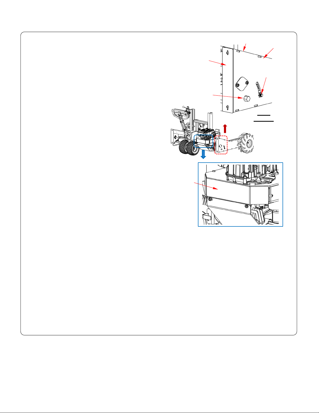
Table of Contents 2/28/2020 ALL-T-2/4-GPT MANUAL
Drive belt
guard
Cover
plate
Cover
plate
Drive
housing
Chain guard
Hex
head
Lock
nut
2. Drive chain (one for each drive wheel): every other oil
change, inspect the chains. To access the chains, remove
the cover plates fastened to both ends of the drive housing.
Refer to the appropriate Sprocket Drive Subassembly on
pages 23 and 24.
A. Check the tension of both chains. They should not be
taut but also should not be so loose that they slap
against the housing or jump on the sprockets. Adjust
the chains by applying pressure to the hex head with a
wrench while loosening the lock nut.
B. Check set screws on the front and rear sprockets,
drive shaft coupling, motor pulley, and pump
pulley. Confirm that the set screws are tight. Tighten
all loose screws. Apply thread locker to keep
connections tight.
C. The front wheel sprocket should line up with the axle
sprocket
D. Lubricate the drive chains with spray grease as
needed, e.g. if the drive train becomes noisy.
3. At least once per month, remove the drive belt guard.
Determine the condition of the drive belt (Exploded Views on
pages 9-17; part number 50-042-008; 50-042-009; or 50-042-
010) and drive pulley (part number 50-027-003; or 50-027-
004). Unseat the belt from the drive pulleys to relieve belt
tension. Then, examine the pump assembly (part number 50643-012 or 50-643-001): Idler pulley on top of the pump as
well as the pump bearings and shaft. Look for damage and
significant wear. Replace any component that is significantly
worn, in particular, the belt.
4. Check the hydraulic system.
a. Before each use:
i. Cycle the carriage all the way up and then all the way down. Movement should be smooth in both
directions, i.e. no binding, jumps, skips.
ii. Check the hydraulic hoses for signs of wear, kinks, cuts, etc. Replace damaged hoses.
b. At least once per month, examine the hydraulic oil. The oil reservoir is located next to the hydraulic pump.
First, fully lower the carriage. Remove the brass fill plug from the top of the reservoir and examine the oil.
Change the oil if it darkens, becomes gritty, or has a milky appearance (indicating that water is present).
Replace the oil with AW-32 hydraulic fluid or its equivalent.
c. Before each use,
5. Before each use make sure all labels are in place & in readable condition. See Labeling diagram on p. 25.
6. Periodically clean dirt and debris from all surfaces to keep the finish in good condition. Store the unit indoors.
Table of Contents Copyright 2019 Vestil Manufacturing Corp. Page 8 of 26
Page 9

Table of Contents 2/28/2020 ALL-T-2/4-GPT MANUAL
Bill of Materials continues on page 10
50-006-014
Complete Exploded View and Bill of Materials: ALL-T-2-GPT, ALL-T-4-GPT, ALL-
Item
Part no.
Description
Qty.
Item
Part no.
Description
Qty.
50-514-022
Weldment, frame assembly:
ALL-T-2-GPT-L & ALL-T-4-GPT-L
1
2
50-538-001
Weldment, carriage
1
13
50-540-009
Assembly, lever, brake
1
99-021-901-001
Cylinder, hydraulic:
ALL-T-4-GPT & ALL-T-4-GPT-L
2
•4
50-612-008
Assembly, axle, rear wheel (1)
1
15
50-024-012
Cover, lower belt, formed
1
5
50-612-006
Assembly, transaxle, 3/4” shaft
1
16
50-024-014
Cover, skid plate
1
••6
50-525-002
Weldment, steering handle
1
17
50-040-010
OR4 TA neutral lever
1
50-542-005
Subassembly, sprocket drive, left
ALL-T-2-GPT-L & ALL-T-4-GPT-L
50-542-006
Subassembly, sprocket drive,
ALL-T-2-GPT-L & ALL-T-4-GPT-L
9
50-145-002
Coupler, drive shaft
1
20
50-024-016
Cover, front leg
2
50-028-002
Fork:
ALL-T-4-GPT-L
2
11
15-527-004
Subassembly, roller
4
22
99-145-104
U-nut
2
T-2-GPT-L, & ALL-T-4-GPT-L
1
50-514-004
ALL-T-2-GPT & ALL-T-4-GPT
12
1
50-540-006 Weldment, shifter plate 1
3
99-021-906-001
ALL-T-2-GPT & ALL-T-2-GPT-L
14
2
50-024-011 Cover, rear belt 1
•••7
50-542-003
(exploded view on p. 18):
ALL-T-2-GPT & ALL-T-4-GPT
18
1
1
50-016-024 Bracket, neutral, formed 1
••••8
10
50-542-004
50-026-002 Shaft, drive 1
Table of Contents Copyright 2019 Vestil Manufacturing Corp. Page 9 of 26
right (exploded view on p. 17):
ALL-T-2-GPT & ALL-T-4-GPT
19
1
1
21
50-024-006 Cover, rear leg 2
38-028-007
38-028-013
50-028-001
ALL-T-2-GPT
ALL-T-4-GPT
ALL-T-2-GPT-L
2
2
2
Page 10

Table of Contents 2/28/2020 ALL-T-2/4-GPT MANUAL
Item
Part no.
Description
Qty.
Item
Part no.
Description
Qty.
23
29185
Screw, machine, truss head
13
*48
50-042-008
Belt, 1/2” x 38”
1
Screw, socket set, black
oxide, 1/4”-20 x 1/4”
Bolt, HHCS, #2, zinc-plated,
/8”-16 x 23/4”
Accessories, electrical, 9V
battery clip
Hex nut, gr. A, z-plated, 3/8”16
Accessories, Electrical, (V
battery snap
Adjustable yoke end,
2”x6/16”x5/8”x1/4”-28
Bolt, HHCS, #2, z-plated,
/16”-18 x 3/4”
Hex bolt, gr. A, z-plated,
/4”-20 x 4”
Cotter pin, z-plated, 1/16” x
/2”
Nylon lock nut, gr. 2, zfinish, 1/4”-20
Bolt, cylinder retaining, 1/2”13 x 2”
Hex bolt, gr. A, z-finish, 3/8”16 x 11/2”
Nylon insert lock nut, gr. 2,
zinc finish, 3/8”-16
Narrow machinery bushing,
plain, 13/4” x 18ga.
Hose, subassembly,
cylinder
External retaining ring,
phosphate finish, 11/8”
Subassembly, hose, valve
return
36
23203
Bolt, SHCS, 1/4”-20 x 3/4”
1
*61
50-623-010
Subassembly, hose, pump
1
Hex nut, gr. A, z-plated, 1/4”20
38
50-130-006
Pin, key, axle extension
1
*63
50-623-006
Subassembly, hose, suction
1
Thread-cutting screw,
/16”-18 x 3/4”
Bolt, #2, z-plated. 5/16”18UNC x 11/2”
Fitting, hydraulic, 06MJ12MP 90° elbow
Fitting, hydraulic, 06MJ08MP 90° elbow
*42
99-159-007
Engine, 190cc
1
*67
99-031-078
Accessories, pipe, 3/4” NPT
1
*43
50-638-002
Assembly, T3 valve
1
*68
01-031-005
Filter, reservoir, hydraulic
1
Subassembly, pump,
hydraulic gear
Accessories, clamp, 2 ear,
17/16”
Accessories, clamp, 2 ear,
11/8”
*47
50-540-003
Assembly, belt tensioner
1
24
25326
2
*49
99-034-134 Horn 1
25
26
11114
36106
3
4
4
*50
50-034-003
*51
50-139-001 Battery, 9V 1
27
50-145-009 Transaxle link, threaded rod 1
*52
50-034-002
28
29
43520
50-120-001 Nut, brake 1
1
*53
99-130-001 Pin, keystock 1
*54
11053
5
30
31
32
66026 Pin, clevis,
65012
01-118-001
1
1
/4” x 1” 1
2
1
*55
*56
*57
11019
37018
11109
1
33
15-112-002 Pin, cylinder bracket 1
34
33454
8
*58
*59
37024
50-623-009
35
68021
2
*60
50-623-008
37
36102
3
*62
50-623-007 Subassembly, hose, return 1
39
32416
slotted, type F, z-plated,
5
4
*64
50-623-011 Subassembly, hose, valve 1
40
11059
1
*65
99-116-074
41
99-145-105 U-nut, 1/4”-20 11
*66
99-116-073
*44
50-643-001
1
*69
99-031-094 Accessories, cap 3/4” 1
*45
*46
50-027-003 Pulley, engine 1
50-523-001 Subassembly, reservoir 1
*70
*71
99-031-095
99-031-096
• Item 4 shown in Rear Wheel Axle Assembly (1) Exploded View on p. 17.
•• Item 6 shown in Steering Handle Subassembly Exploded View on p. 18.
••• Item 7 shown in Sprocket Drive Subassembly, Left Side, Exploded Views on p. 24.
•••• Item 8 shown in Sprocket Drive Subassembly, Right Side, Exploded Views on p. 23.
* Components of Power Unit Subassembly 50-160-002 on p. 20.
1
1
3
1
1
3
3
1
1
2
2
1
1
Table of Contents Copyright 2019 Vestil Manufacturing Corp. Page 10 of 26
Page 11

Table of Contents 2/28/2020 ALL-T-2/4-GPT MANUAL
Complete Exploded View and Bill of Materials: ALL-T-2-GPT-10HP, ALL-T-4-GPT-
Bill of Materials continues on page 12
50-006-015
Item
Part no.
Description
Qty.
Item
Part no.
Description
Qty.
Weldment, frame assembly:
10HP
2
50-538-001
Weldment, carriage
1
11
15-527-004
Subassembly, roller
4
10HP
•4
50-632-002
Assembly, axle, rear wheel (2)
1
13
50-540-009
Assembly, lever, brake
1 5 50-612-007
Assembly, transaxle, 1” shaft
1
14
50-024-006
Cover, rear leg
2
••6
50-525-002
Weldment, steering handle
1
15
50-024-016
Cover, front leg
2
Subassembly, sprocket drive, left
10HP
50-028-002
Fork:
ALL-T-4-GPT-L
2
Subassembly, sprocket drive, right
10HP
9
50-145-004
Coupler, drive shaft
1
18
29185
Screw, machine, truss head
13
10HP, ALL-T-2-GPT-L-10HP & ALL-T-4-GPT-L-10HP
1
50-514-024
50-514-025
ALL-T-2-GPT-10HP & ALL-T-4-GPT-10HP
ALL-T-2-GPT-L-10HP & ALL-T-4-GPT-L-
10
1
1
50-026-001 Shaft, drive 1
99-021-906-001
3
99-021-901-001
Cylinder, hydraulic:
ALL-T-2-GPT-10HP & ALL-T-4-GPT-10HP
ALL-T-2-GPT-L-10HP & ALL-T-4-GPT-L-
12
1
1
50-540-006 Weldment, shifter plate 1
•••7
50-542-007
50-542-009
50-542-008
•••8
50-542-010
Table of Contents Copyright 2019 Vestil Manufacturing Corp. Page 11 of 26
(exploded view on p. 18):
ALL-T-2-GPT-10HP & ALL-T-4-GPT-10HP
ALL-T-2-GPT-L-10HP & ALL-T-4-GPT-L-
(exploded view on p. 17):
ALL-T-2-GPT-10HP & ALL-T-4-GPT-10HP
ALL-T-2-GPT-L-10HP & ALL-T-4-GPT-L-
1
1
1
1
38-028-007
16
38-028-013
50-028-001
17
99-145-105 U-nut,
ALL-T-2-GPT
ALL-T-4-GPT
ALL-T-2-GPT-L
1
/4”-20 9
2
2
2
Page 12

Table of Contents 2/28/2020 ALL-T-2/4-GPT MANUAL
Item
Part no.
Description
Qty.
Item
Part no.
Description
Qty.
Bolt, HHCS, #2, zinc-plated,
/8”-16 x 23/4”
20
36106
Hex nut, gr. A, z-plated, 3/8”-16
5
*48
50-042-009
Belt, 1/2” x 40”
1
21
50-145-009
Transaxle link, threaded rod
1
*49
99-034-134
Horn
1
Adjustable yoke end,
2”x6/16”x5/8”x1/4”-28
Accessories, electrical, 9V
battery clip
23
50-120-001
Nut, brake
2
*51
50-139-001
Battery, 9V
1
Accessories, Electrical, (V
battery snap
25
*53
Bolt, cylinder retaining, 1/2”-13
x 2”
Bolt, HHCS, #2, z-plated,
/16”-18 x 3/4”
Hex bolt, gr. A, z-plated, 1/4”20 x 4”
Narrow machinery bushing,
plain, 13/4” x 18ga.
Nylon lock nut, gr. 2, z-finish,
/4”-20
External retaining ring,
phosphate finish, 11/8”
Hex bolt, gr. A, z-finish, 3/8”16 x 11/2”
Nylon insert lock nut, gr. 2,
zinc finish, 3/8”-16
31
36102
Hex nut, gr. A, z-plated, 1/4”-20
3
*59
50-623-009
Hose, subassembly, cylinder
1
Subassembly, hose, valve
return
Bolt, #2, z-plated. 5/16”-18UNC
x 11/2”
34
50-024-009
Guard, skid plate, 10HP
1
*62
50-623-007
Subassembly, hose, return
1
35
50-024-017
Guard, skid plate top, formed
1
*63
50-623-006
Subassembly, hose, suction
1
36
*64
Battery, 12V, sealed leadacid (AGM)
Thread-cutting screw, slotted,
type F, z-plated, 1/4”-20 x 3/4”
Accessories, motor contactor,
12V coil
Bracket, drive to neutral,
formed
Weldment, handle, drive to
neutral
Hex bolt, gr. A, z-finish, 1/4”20 x 3/4”
Hex bolt, gr. A, z-finish, 3/8”-16
x 3/4”
Accessories, battery box,
series 16
*42
99-659-001
Assembly, engine, 190cc
1
*70
99-031-078
Accessories, pipe, 3/4” NPT
1
*43
50-638-002
Assembly, T3 valve
1
*71
99-031-094
Accessories, cap 3/4”
1
Subassembly, pump, hydraulic
gear
Fitting, hydraulic, 06MJ-08MP
90° elbow
Fitting, hydraulic, 06MJ-12MP
90° elbow
19
11114
3
4
*47
50-540-005 Assembly, belt tensioner 1
22
43520
1
*50
50-034-003
24
26
66026 Pin, clevis,
65012 Cotter pin, z-plated, 1/16” x 1/2” 3
01-118-001
1
/4” x 1” 1
1
*52
50-034-002
99-130-003 Pin, keystock 1
*54
11053
5
27
15-112-002 Pin, cylinder bracket 1
28
33454
8
*55
*56
11019
37018
1
29
30
68021
23203 Bolt, SHCS,
1
/4”-20 x 3/4” 1
2
*57
*58
11109
37024
32
50-130-007 Pin, key, axle extension 1
33
11059
1
*60
50-623-008
*61
50-623-010 Subassembly, hose, pump 1
50-024-015 Guard, right side transaxle 1
37
50-514-005 Weldment, battery box 1
38
32408
2
50-623-011 Subassembly, hose, valve 1
*65
21-139-002
*66
99-034-028
39
40
50-016-008
50-525-001
1
1
*67
21-034-004 Circuit breaker 1
*68
11003
41
11103
1
*69
50-034-004
*44
50-643-001
1
*72
01-031-005 Filter, reservoir, hydraulic 1
*45
• Item 4 shown in Rear Wheel Axle Assembly (2) Exploded View on p. 17.
•• Item 6 shown in Steering Handle Subassembly Exploded View on p. 18.
••• Item 7 shown in Sprocket Drive Subassembly, Left Side, Exploded Views on p. 24.
•••• Item 8 shown in Sprocket Drive Subassembly, Right Side, Exploded Views on p. 23.
* Components of Power Unit Subassembly 50-160-003 on p. 20.
50-027-004 Pulley, engine 1
*46
50-523-001 Subassembly, reservoir 1
*73
*74
99-116-073
99-116-074
1
1
3
1
3
4
4
1
1
1
2
1
2
2
Table of Contents Copyright 2019 Vestil Manufacturing Corp. Page 12 of 26
Page 13

Table of Contents 2/28/2020 ALL-T-2/4-GPT MANUAL
Bill of Materials continues on page 14
50-006-022
Complete Exploded View and Bill of Materials: ALL-T-2-GPT-PT, ALL-T-4-GPT-PT,
Item
Part no.
Description
Qty.
Item
Part no.
Description
Qty.
1
50-514-027
Subassembly, frame, tilt
1
16
50-026-002
Shaft, drive
1
2
50-514-023
Weldment, frame assembly
1
17
50-540-006
Weldment, shifter plate
1 3 50-538-002
Weldment, carriage
1
18
50-540-009
Assembly, lever, brake
1 4 50-514-012
Weldment, frame, tilt mast
1
19
50-024-017
Guard, skid plate, top, formed
1
5
15-527-004
Subassembly, roller
4
20
50-024-009
Guard, skid plate, 10HP
1
Assembly, cylinder, hydraulic, 2”x21/4”
hand port)
Assembly, cylinder, hydraulic, 2x21/4”
hand port)
8
03-612-002
Assembly, hinge pin
4
23
50-024-016
Cover, front leg
2
99-021-952
Cylinder, hydraulic
PT
ALL-T-4-GPT-PT & ALL-T-4-GPT-L-PT
1
•10
50-623-002
Assembly, axle, rear wheel (2)
1
25
99-145-105
U-nut, 1/4”-20
9
11
50-612-006
Assembly, transaxle, 3/4” shaft
1
26
29185
Screw, machine, truss head
13
Socket set screw, black oxide, 1/4”20x1/4”
Bolt, HHCS #2, z-plated, 3/8”16x23/4”
••••14
50-542-006
Subassembly, sprocket, drive, right
1
29
36106
Hex nut, gr. A, z-plated, 3/8”-16
4
15
50-145-002
Coupler, drive shaft
1
30
50-145-009
Transaxle link, threaded rod
1
ALL-T-2-GPT-L-PT, & ALL-T-4-GPT-L-PT
6
50-521-001
piston style with clevis mounts (right
21
1
50-016-024 Bracket, neutral, formed 1
7
50-521-002
piston style with clevis mounts (left
22
1
50-024-006 Cover, rear leg 2
9
99-021-909-001
••12 50-525-002 Weldment, steering handle 1 27
•••13 50-542-005 Subassembly, sprocket, drive, left 1
Table of Contents Copyright 2019 Vestil Manufacturing Corp. Page 13 of 26
ALL-T-2-GPT-PT & ALL-T-2-GPT-L-
24
1
50-040-010 OR4 TA neutral lever 1
25326
28
11114
2
4
Page 14

Table of Contents 2/28/2020 ALL-T-2/4-GPT MANUAL
Item
Part no.
Description
Qty.
Item
Part no.
Description
Qty.
Adjustable yoke end,
2”x7/16’x5/8”x1/4”-28
Accessories, 9V battery
snap
32
50-120-001
Nut, brake
1
*55
99-130-001
Pin, keystock
1
Bolt, HHCS, #2, z-plated,
/16”-18x2”
Cotter pin, z-plated,
/16”x1/2”
Hex bolt, gr. A, z-plated,
/4”-20x4”
Nylon lock nut, gr. 2, zfinish, 1/4”-20
Narrow machinery bushing,
plain, 13/4” x 18ga.
Hex bolt, gr. A, z-finish, 3/8”16x11/2”
External retaining ring,
phosphate finish, 11/8”
Nylon insert lock nut, gr. 2,
z-finish, 3/8”-16
Bolt, SHCS, utility grade,
/4”-20x3/4”
Subassembly, hose,
suction, tank-to-pump
Hex nut, gr. A, z-plated, 1/4”20
Subassembly, hose, return,
valve-to-tank
Subassembly, hose, bottom
bulkhead-to-cylinder
Bolt, #2, z-plated, 5/16”18UNCx11/2”
Subassembly,, hose, top
tilt, bulkhead-to-block
50-028-002
Fork
ALL-T-4-GPT-L-PT
Fitting, hydraulic,
06MJ08MA ORB 90° elbow
Fitting, hydraulic, 06MJ08MORB STRAIGHT
*45
50-638-001
Assembly, valve, double
1
*68
99-031-078
Accessories, pipe, 3/4” NPT
1
Subassembly, pump,
hydraulic gear
*47
50-027-003
Pulley, engine
1
*70
99-031-094
Accessories, cap, 3/4”
1
Subassembly, hose, tilt,
valve-to-bulkhead
Subassembly, hose, lift,
valve-to-bulkhead
Subassembly, hose, blockto-tilt-cylinder
Fitting, hydraulic, 06MJ08MP 90° elbow
Accessories, clamp, 2 ear,
17/16”
Accessories, clamp, 2 ear
11/8”
31
43520
33
66026 Pin, clevis,
34
35
65012
15-112-002 Pin, cylinder bracket 1
36
37
33454
68021
38
23203
39
36102
40
50-130-006 Pin, key, axle extension 1
41
11059
38-028-007
42
38-028-013
50-028-001
43
50-024-015 Guard, right side transaxle 1
*44
99-159-007 Engine 190cc 1
*46
50-643-001
*48
50-523-001 Subassembly, reservoir 1
*49
50-540-003 Assembly, belt tensioner 1
*50
50-042-010 Belt,1/2”x46” 1
*51
99-034-134 Horn, ALL-T 1
*52
50-034-003 Accessories, 9V battery clip 1
*53
1
• Item 10 shown in Rear Wheel Axle Assembly (2) Exploded View on p. 17.
•• Item 12 shown in Steering Handle Subassembly Exploded View on p. 18.
••• Item 13 shown in Sprocket Drive Subassembly, Left Side, Exploded Views on p. 24.
•••• Item 14 shown in Sprocket Drive Subassembly, Right Side, Exploded Views on p. 23.
* Components of Power Unit Subassembly 50-160-004 on p. 21.
50-139-001 Battery, 9V 1
Table of Contents Copyright 2019 Vestil Manufacturing Corp. Page 14 of 26
1
/4”x1” 1
1
1
ALL-T-2-GPT-PT
ALL-T-4-GPT-PT
ALL-T-2-GPT-L-PT
1
2
8
2
1
3
1
2
1
*54
50-034-002
*56
*57
*58
*59
*60
*61
*62
*63
*64
*65
*66
*67
*69
*71
*72
*73
*74
*75
*76
11061
11019
37018
11109
37024
50-623-012
50-623-013
50-623-014
50-623-015
50-623-016
99-116-119
99-116-096
01-031-005 Filter, reservoir, hydraulic 1
50-623-017
50-623-019
50-623-018
99-116-073
99-031-095
99-031-096
5
1
tilt, bulkhead-to-block & lift,
Subassembly, hose, valveto-pump
1
3
1
1
3
3
1
1
2
1
1
2
3
2
1
4
1
1
1
Page 15

Table of Contents 2/28/2020 ALL-T-2/4-GPT MANUAL
Bill of Materials continues on page 16
50-006-026
Item
Part no.
Description
Qty.
Item
Part no.
Description
Qty.
1
50-514-026
Subassembly, frame, tilt
1
14
50-145-004
Coupler, drive shaft
1
2
50-538-002
Weldment, carriage
1
15
50-026-001
Shaft, drive
1 3 50-514-012
Weldment, frame, tilt mast
1
16
50-540-006
Weldment, shifter plate
1
4
15-527-004
Subassembly, roller
4
17
50-540-009
Assembly, lever, brake
1
Assembly, cylinder, hydraulic, 2”x21/4”
hand port)
Assembly, cylinder, hydraulic, 2x21/4”
hand port)
7
03-612-002
Assembly, hinge pin
4
20
50-024-006
Cover, rear leg
2
Cylinder, hydraulic
GPT-L-PT-10HP
•9
50-623-002
Assembly, axle, rear wheel (2)
1
22
99-145-105
U-nut, 1/4”-20
9
10
50-612-007
Assembly, transaxle, 3/4” shaft
1
23
29185
Screw, machine, truss head
13
Bolt, HHCS #2, z-plated, 3/8”16x23/4”
•••12
50-542-009
Subassembly, sprocket, drive, left
1
25
36106
Hex nut, gr. A, z-plated, 3/8”-16
4
••••13
50-542-010
Subassembly, sprocket, drive, right
1
26
50-145-009
Transaxle link, threaded rod
1
Complete Exploded View and Bill of Materials: ALL-T-2-GPT-PT-10HP; ALL-T-4GPT-PT-10HP; ALL-T-2-GPT-L-PT-10HP; & ALL-T-4-GPT-L-PT-10HP
5
50-521-001
piston style with clevis mounts (right
18
1
50-024-017 Guard, skid plate, top, formed 1
6
50-521-002
piston style with clevis mounts (left
19
1
50-024-009 Guard, skid plate, 10HP 1
99-021-909-001
8
••11 50-525-002 Weldment, steering handle 1 24
99-021-952
Table of Contents Copyright 2019 Vestil Manufacturing Corp. Page 15 of 26
ALL-T-2-GPT-PT-10HP & ALL-T-2-
ALL-T-4-GPT-PT-10HP & ALL-T-4-
GPT-L-PT-10HP
21
1
1
50-024-016 Cover, front leg 2
11114
4
Page 16

Adjustable yoke end,
2”x7/16’x5/8”x1/4”-28
Bolt, HHCS, #2, z-plated, 5/16”18x2”
Hex bolt, gr. A, z-plated, 1/4”20x4”
Nylon lock nut, gr. 2, z-finish,
/4”-20
Nylon insert lock nut, gr. 2, zfinish, 3/8”-16
Narrow machinery bushing,
plain, 13/4” x 18ga.
Subassembly, hose, suction,
tank-to-pump
External retaining ring,
phosphate finish, 11/8”
Subassembly, hose, return,
valve-to-tank
Subassembly, hose, bottom tilt,
bulkhead-to-cylinder
Subassembly,, hose, top tilt,
bulkhead-to-block
Subassembly, hose, valve-topump
Bolt, #2, z-plated, 5/16”18UNCx11/2”
Fitting, hydraulic, 06MJ08MA
ORB 90° elbow
50-028-002
Fork
ALL-T-4-GPT-L-PT
39
50-024-015
Guard, right side transaxle
1
*67
99-031-078
Accessories, pipe, 3/4” NPT
1
40
50-016-008
Bracket, drive-to-neutral, formed
1
*68
01-031-005
Filter, reservoir, hydraulic
1
Weldment, handle, drive-toneutral
Subassembly, hose, tilt, valveto-bulkhead
Screw, thread cutting, 1/4”20x3/4”
Subassembly, hose, lift, valveto-bulkhead
Subassembly, hose, block-to-tiltcylinder
Fitting, hydraulic, 06MJ-08MP
90° elbow
Subassembly, pump, hydraulic
gear
*47
50-027-004
Pulley, motor
1
*75
99-031-096
Accessories, clamp, 2 ear 11/8”
1
*48
50-523-001
Subassembly, reservoir
1
*76
21-139-002
Battery, 12V, sealed lead-acid
1
Accessories, motor
contactor,12V coil
Accessories, electrical battery
box, series 16
Hex bolt, gr. A, z-finish, 3/8”16x11/2”
*53
*54
Table of Contents 2/28/2020 ALL-T-2/4-GPT MANUAL
Item Part no. Description Qty. Item Part no. Description Qty.
27
28
43520
50-120-001 Nut, brake 1
*55
1
99-130-003 Pin, keystock 1
*56
11061
29
30
66026 Pin, clevis,
65012 Cotter pin, z-plated,
1
/4”x1” 1
1
/16”x1/2” 2
*57
*58
11019
37018
1
31
15-112-002 Pin, cylinder bracket 1
32
33
34
33454
68021
23203
Bolt, SHCS, utility grade,
3
/4”
20x
1
/4”-
*59
*60
8
*61
2
*62
1
37024
50-623-012
50-623-013
50-623-014
bulkhead-to-block & lift,
35
36
36102 Hex nut, gr. A, z-plated,
50-130-007 Pin, key, axle extension 1
1
/4”-20 3
*63
*64
50-623-015
50-623-016
37
38
11059
38-028-007
38-028-013
50-028-001
ALL-T-2-GPT-PT
ALL-T-4-GPT-PT
ALL-T-2-GPT-L-PT
*65
1
2
*66
99-116-119
99-116-096
Fitting, hydraulic, 06MJ08MORB STRAIGHT
41
50-525-001
42
50-514-005 Weldment, battery box 1
*69
1
99-031-094 Accessories, cap, 3/4” 1
*70
50-623-017
43
*44
32408
99-659-001 Assembly, engine, 344cc 1
*71
2
*72
50-623-019
50-623-018
*45
50-638-001 Assembly, valve, double 1
*46
50-643-001
*73
99-116-073
*74
1
99-031-095 Accessories, clamp, 2 ear, 17/16” 1
*49
50-540-003 Assembly, belt tensioner 1
*50
50-042-008 Belt, 1/2”x38” 1
*51
99-034-134 Horn 1
*77
99-034-028
*78
21-034-004 Circuit breaker 1
*79
50-034-004
*52
1
• Item 9 shown in Rear Wheel Axle Assembly (2) Exploded View on p. 17.
•• Item 11 shown in Steering Handle Subassembly Exploded View on p. 18.
••• Item 12 shown in Sprocket Drive Subassembly, Left Side, Exploded Views on p. 24.
•••• Item 13 shown in Sprocket Drive Subassembly, Right Side, Exploded Views on p. 23.
* Components of Power Unit Subassembly 50-160-005 on p. 22.
50-034-003 Accessories, 9V battery clip 1
50-139-001 Battery, 9V 1
50-034-002 Accessories, 9V battery snap 1
*80
*81
11109
11003
Hex bolt, gr. A, z-plated, 1/4”20x3/4”
3
1
1
3
1
1
2
1
1
2
3
2
1
4
1
1
1
4
2
Table of Contents Copyright 2019 Vestil Manufacturing Corp. Page 16 of 26
Page 17

Table of Contents 2/28/2020 ALL-T-2/4-GPT MANUAL
Item
Part no.
Description
Qty.
1
2
3
1
Machine bushing, low
carbon, plain, 3/4”x18ga.
Extended prong cotter pin,
z-finish, 1/8”x11/2”
7
22-110-001
Bearing, upper steering
1 8 50-113-017
Shim, bearing spacer
1 9 50-113-014
Spacer, rear steering
1
Specialty hardware, cap,
hex nut
11
Cotter pin, z-plated,
/16”x11/4”
Bearing, ball, low speed,
rear wheel
15
50-110-008
Bearing, seal
1
Rear Wheel Axle Assembly (2) Exploded View and Bill of Materials
Item
Part no.
Description
Qty. 1 50-612-001
Weldment, rear king pin
1 2 16-132-361
Foam filled tire, 4.80”x8”
2 3 22-110-001
Bearing, upper steering
1 4 50-113-017
Shim, bearing spacer
1
5
Specialty hardware, cap,
hex nut
7
50-110-005
Bearing, tapered
1 8 50-110-006
Bearing, cup
1
Wheel, rim for pneumatic
tire
Slotted jam nut, gr. 2,
plain, 1”-14
11
33444
Machine bushing, 1”x18ga.
2
Extended prong cotter pin,
z-finish, 1/8”x11/2”
13
50-110-007
Bearing, seal
1
Cotter pin, z-plated,
/16”x11/4”
Return to p. 9.
Return to p. 11; p. 13; or p. 15.
Rear Wheel Axle Assembly (1) Exploded View and Bill of Materials
ALL-T-2-GPT; ALL-T-4-GPT; ALL-T-2-GPT-L; ALL-T-4-GPT-L
50-612-008
50-112-013 Pin, rear, king pin 1
50-112-014 Axle, rear 1
64255
4
16-132-235 Tire, rear, foam filled 2
/4”x2” spring pin 1
5
6
10
33424
65078
50-145-010
50-110-002 Bearing, tapered 1
12
50-110-004 Bearing, cup 1
13
14
65124
50-110-003
3
ALL-T-2-GPT-PT; ALL-T-4-GPT-PT; ALL-T-2-GPT-L-PT; ALL-T-4-GPT-L-PT; ALL-T-2-GPT10HP; ALL-T-4-GPT-10HP; ALLT-2-GPT-L-10HP; ALL-T-4-GPT-L-10HP; ALL-T-2-GPT-PT10HP; ALL-T-4-GPT-PT-10HP; ALL-T-2-GPT-L-PT-10HP; ALL-T-4-GPT-L-PT-10HP
50-623-002
4
2
1
1
4
Table of Contents Copyright 2019 Vestil Manufacturing Corp. Page 17 of 26
50-113-014 Spacer, rear steering 1
6
50-145-010
9
16-132-280
10
12
14
36870
65078
65124
3
1
2
2
2
1
Page 18

Table of Contents 2/28/2020 ALL-T-2/4-GPT MANUAL
Qty
.
Specialty hardware, shifter
cable
Hex bolt, gr. A, plain, 3/8”16x21/2”
Adjustable yoke end,
2”x7/16”x5/8”x1/4”-28
4
17
Specialty hardware, shock,
tension
Hex bolt, gr. A, zinc finish,
/8”-16x 11/2”
Nylon insert lock nut, gr. 2,
z-finish, 3/8”-16
Flat washer, USS, z-plated,
/4”
Bolt, HHCS, #2, z-plated,
/8”-16x31/2”
Hex bolt, gr. A, z-plated, 1/4”20x13/4”
Hex nut, gr. A, z-plated, 3/8”16
Switch, PB SPST, normally
closed
Bolt, HHCS, #2, z-plated,
/4”-20x21/2”
Switch, PB SPST, normally
open
Nylon lock nut, gr. 2, z-finish
/4”-20
Hex bolt, gr. A, z-plated,
/4”-16x11/2”
Weldment, frame, handle
mount
Return to p. 9; p. 11;
Steering Handle Subassembly Exploded View and Bill of Materials
50-525-002
p. 13; or p. 15.
Item Part no. Description Qty. Item Part no. Description
1
50-113-002 Spacer, air spring 2
14
50-145-003
2
50-113-03 Spacer, handle 2
3
50-525-003 Weldment, steering handle 1
15
16
11113
43520
1
2
1
50-540-004 Weldment, shifter lever 1
5
50-525-004 Weldment, safety bale 1
6
99-145-015
7
8
9
10
11
12
13
11109
37024
11117
36106
11013
37018
11009
Table of Contents Copyright 2019 Vestil Manufacturing Corp. Page 18 of 26
50-120-001 Nut, brake 1
18
19
1
20
3
3
1
1
1
1
3
4
4
1
3
1
21
22
23
24
25
26
66026 Pin, clevis, 1/4”x1” 1
65012 Cotter pin, z-plated, 1/16”x1/2” 2
50-146-002 Spring, kill switch 1
33004
11010
50-022-001
50-022-002
50-034-001 Boot, switch 2
50-514-040
1
1
1
1
1
1
Page 19

Table of Contents 2/28/2020 ALL-T-2/4-GPT MANUAL
ALL-T-(2 or 4)-GPT Power Unit Subassembly Exploded View and Bill of Materials
Item
Part no.
Description
Qty.
Item
Part no.
Description
Qty.
Engine
ALL-T-GPT-10HP
3
/8”-16 Nylon insert lock nut, gr. 2,
z-finish
Subassembly, pump, hydraulic,
gear
4
50-027-003
Pulley, engine
1
19
50-623-008
Subassembly, hose, valve return
1 5 50-523-001
Subassembly, reservoir
1
20
50-623-010
Subassembly, hose, pump
1 6 50-540-003
Assembly, belt tensioner
1
21
50-623-007
Subassembly, hose, return
1 7 15-042-003
Belt, 1/2”x55”
1
22
50-623-006
Subassembly, hose, suction
1 8 99-034-134
Horn, ALL-T
1
23
50-623-011
Subassembly, hose, valve
1
Accessories, electrical, 9V
battery clip
10
50-139-001
Battery, 9V
1
25
99-116-073
Fitting, hydraulic, 06MJ-08MP 90°
2
Accessories, electrical, 9V
battery snap
5/
16
14
11019
1/
4
”-20x4” hex bolt, gr. A, z-plated
1
29
99-031-095
Accessories, clamp, 2 ear, 17/16”
1
1
/4”-20 Nylon insert lock nut, gr. 2,
z-finish
Return to p. 10
50-160-002
1
2
3
9
11
12
13
99-159-007
ALL-T-GPT: 190cc
50-638-002 Assembly, T3 valve 1
50-643-001
50-034-003
50-034-002
99-130-001 Pin, keystock 1
11053
”-18x3/4”, HHCS, #2, z-plated 3
1
1
1
1
16
17
18
24
26
27
28
11109
37024
50-623-009 Subassembly, hose, cylinder 1
99-116-074 Fitting, hydraulic, 06MJ-12MP 90° 2
99-031-078 Accessories, pipe, 3/4” NPT
01-031-005 Filter, reservoir, hydraulic 1
99-031-094 Accessories, cap, 3/4” 1
3
/8”-16x11/2” hex bolt, gr. A, zinc
finish
3
3
15
37018
Table of Contents Copyright 2019 Vestil Manufacturing Corp. Page 19 of 26
3
30
99-031-096 Accessories, clamp, 2 ear, 11/8” 1
Page 20

Table of Contents 2/28/2020 ALL-T-2/4-GPT MANUAL
ALL-T-(2 or 4)-GPT-10HP and ALL-T-(2 or 4)-GPT-L-10HP
2
19
6
23
Accessories, motor contactor, 12V
coil
Accessories, electrical, 9V battery
clip
Accessories, electrical, 9V battery
snap
5/
1/
1
/4”-20 Nylon insert lock nut, gr. 2, z-
finish
3
/8”-16x11/2” hex bolt, gr. A, zinc
finish
3
/8”-16 Nylon insert lock nut, gr. 2, z-
finish
Return to p. 12
Power Unit Subassembly Exploded View and Bill of Materials
50-160-003
Item Part no. Description Qty. Item Part no. Description Qty.
1
99-659-001 Engine, 344cc 1
50-638-002 Assembly, T3 valve 1
3
50-643-001 Subassembly, pump, hydraulic, gear 1
4
50-027-004 Pulley, engine 1
5
50-523-001 Subassembly, reservoir 1
50-540-005 Assembly, belt tensioner 1
7
50-042-009 Belt, 1/2”x40” 1
8
99-034-134 Horn, ALL-T 1
9
50-034-003
10
50-139-001 Battery, 9V 1
11
50-034-002
12
99-130-003 Pin, keystock 1
13
14
15
11053
11019
37018
”-18x3/4”, HHCS, #2, z-plated 3
16
”-20x4” hex bolt, gr. A, z-plated 1
4
18
50-623-009 Subassembly, hose, cylinder 1
50-623-008 Subassembly, hose, valve return 1
20
50-623-010 Subassembly, hose, pump 1
21
50-623-007 Subassembly, hose, return 1
22
50-623-006 Subassembly, hose, suction 1
50-623-011 Subassembly, hose, valve 1
24
21-139-002 Battery, 12V sealed lead-acid AGM 1
25
99-034-028
26
1
1
3
21-034-004 Circuit breaker 1
27
28
29
30
31
32
11003 Hex bolt, gr. A, z-plated, 1/4”-20 x 3/4” 2
50-034-004 Accessories, battery box, series 16 1
99-031-078 Accessories, pipe, 3/4” NPT 1
99-031-094 Accessories, cap, 3/4” 1
01-031-005 Filter, reservoir, hydraulic 1
99-116-073 Fitting, hydraulic, 06MJ-08MP 90° 2
1
16
17
11109
37024
Table of Contents Copyright 2019 Vestil Manufacturing Corp. Page 20 of 26
33
4
4
99-116-074 Fitting, hydraulic, 06MJ-12MP 90° 2
Page 21

Table of Contents 2/28/2020 ALL-T-2/4-GPT MANUAL
ALL-T-(2 or 4)-GPT-PT and ALL-T-(2 or 4)-GPT-L-PT
Item
Part no.
Description
Qty.
Item
Part no.
Description
Qty.
Subassembly, pump, hydraulic,
gear
Subassembly, hose, bottom tilt, bulkhead
to block & lift, bulkhead to cylinder
Subassembly, hose, top tilt, bulkhead to
block
6
23
Accessories, electrical, 9V battery
clip
Accessories, electrical, 9V battery
snap
Subassembly, hose, tilt, hose to bulkhead
Subassembly, hose, lift, valve to
bulkhead
5/
1/
1
/4”-20 Nylon insert lock nut, gr. 2,
z-finish
3
/8”-16x11/2” hex bolt, gr. A, zinc
finish
3
/8”-16 Nylon insert lock nut, gr. 2,
z-finish
Return to p. 14
Power Unit Subassembly Exploded View and Bill of Materials
50-160-004
1
99-159-007 Engine, 190cc 1
2
50-638-001 Assembly, valve, double 1
3
50-643-001
4
50-027-003 Pulley, engine 1
5
50-523-001 Subassembly, reservoir 1
50-540-003 Assembly, belt tensioner 1
7
50-042-010 Belt, 1/2”x40” 1
8
99-034-134 Horn, ALL-T 1
9
50-034-003
10
50-139-001 Battery, 9V 1
11
50-034-002
12
99-130-001 Pin, keystock 1
13
14
15
16
11061
11019
37018
11109
”-18x2”, HHCS, #2, z-plated 3
16
”-20x4” hex bolt, gr. A, z-plated 1
4
18
50-623-012 Subassembly, hose, suction tank to pump 1
19
50-623-013 Subassembly, hose, return valve to tank 1
20
1
1
1
1
3
50-623-014
21
50-623-015
22
50-623-016 Subassembly, hose, valve to pump 1
99-116-119 Fitting, hydraulic, 06MJ-08MAORB 90° 2
24
99-116-073 Fitting, hydraulic, 06MJ-08MP 90° 1
25
99-031-078 Accessories, pipe, 3/4” NPT 1
26
01-031-005 Filter, reservoir, hydraulic 1
27
99-031-094 Accessories, cap, 3/4” 1
28
50-623-017
29
50-623-019
30
50-623-018 Subassembly, hose, block to tilt 4
31
99-116-096 Fitting, hydraulic, 06MJ-08MORB straight 3
32
99-031-095 Accessories, clamp, 2 ear, 17/16” 1
33
99-031-096 Accessories, clamp, 2 ear, 11/8” 1
2
1
2
1
17
37024
Table of Contents Copyright 2019 Vestil Manufacturing Corp. Page 21 of 26
3
Page 22

Table of Contents 2/28/2020 ALL-T-2/4-GPT MANUAL
Subassembly, hose, top tilt, bulkhead to
block
Subassembly, hose, tilt, hose to
bulkhead
Subassembly, hose, lift, valve to
bulkhead
Fitting, hydraulic, 06MJ-08MORB
straight
1
/4”-20 Nylon insert lock nut, gr. 2, z-
finish
3
/8”-16 Nylon insert lock nut, gr. 2, z-
finish
Subassembly, hose, suction tank to
pump
Subassembly, hose, return valve to
tank
Subassembly, hose, bottom tilt,
cylinder
ALL-T-(2 or 4)-GPT-PT-10HP & ALL-T-(2 or
Return to p. 16
4)-GPT-L-PT-10HP Power Unit Subassembly
Exploded View and Bill of Materials
50-160-005
Item Part no. Description Qty. Item Part no. Description Qty.
1 99-659-001 Engine, 344cc 1 20 50-623-015
2 50-638-001 Assembly, valve, double 1 21 50-623-016 Subassembly, hose, valve to pump 1
3 50-643-001 Subassembly, pump, hydraulic, gear 1 22 99-116-119 Fitting, hydraulic, 06MJ-08MAORB 90° 2
4 50-027-004 Pulley, engine 1 23 99-116-073 Fitting, hydraulic, 06MJ-08MP 90° 1
5 50-523-001 Subassembly, reservoir 1 24 99-031-078 Accessories, pipe, 3/4” NPT 1
6 50-540-003 Assembly, belt tensioner 1 25 01-031-005 Filter, reservoir, hydraulic 1
7 50-042-008 Belt, 1/2”x38” 1 26 99-031-094 Accessories, cap, 3/4” 1
8 99-034-134 Horn, ALL-T 1 27 50-623-017
9 50-034-003 Accessories, electrical, 9V battery clip 1 28 50-623-019
10 50-139-001 Battery, 9V 1 29 50-623-018 Subassembly, hose, block to tilt 4
11 50-034-002 Accessories, electrical, 9V battery snap 1 30 99-116-096
12 99-130-003 Pin, keystock 1 31 99-031-095 Accessories, clamp, 2 ear, 17/16” 1
13 11061
14 11019
15 37018
16 37024
17 50-623-012
5/
”-18x2”, HHCS, #2, z-plated 3 32 99-031-096 Accessories, clamp, 2 ear, 11/8” 1
16
1/
”-20x4” hex bolt, gr. A, z-plated 1 33 21-139-002 Battery, 12V, sealed lead-acid (AGM) 1
4
1
2
1
3
3 34 99-034-028 Accessories, motor contactor 12V coil 1
3 35 21-034-004 Circuit breaker 1
1 36 50-034-004 Accessories, battery box, series 16 1
18 50-623-013
19 50-623-014
Table of Contents Copyright 2019 Vestil Manufacturing Corp. Page 22 of 26
bulkhead to block & lift, bulkhead to
1 37 11109 Hex bolt, gr. A, z-finish, 3/8”-16 x 11/2” 4
2 38 11003 Hex bolt, gr. A, z-plated, 1/4”-20 x 3/4” 2
Page 23

Table of Contents 2/28/2020 ALL-T-2/4-GPT MANUAL
50-145-007
Chain:
ALL-T-4-GPT-L-10HP
1
Thread cutting screw, type F,
/16”-18 x 1/2”
Thread cutting screw, slotted,
type F, 5/16”-18 x 3/4”
Bolt, HHCS, z-plated, 5/16”-18 x
/4”
50-145-007
Chain:
ALL-T-2-GPT-L & ALL-T-4-GPT-L
1
Thread cutting screw, type F, 5/16”18 x 1/2”
Thread cutting screw, slotted, type
F, 5/16”-18 x 3/4”
Sprocket Drive Subassembly, Right Side Exploded View and Bill of Materials
ALL-T-2-GPT-10HP; ALL-T-4-GPT-10HP;
ALL-T-2-GPT-L-10HPL & ALL-T-4-GPT-L-10HP
(50-542-008 & 50-542-010 on p. 11 or p. 15)
Item Part no. Description Qty.
1 50-612-002 Assembly, front axle 1
2 15-110-001 Bearing, ball, front axle 1
3 16-132-229 Tire, front left, foam filled 1
4 50-110-001 Bearing, flange mount 2
5 50-042-005 Sprocket, roller chain, front wheel 1
6 50-540-008 Subassembly, chain tensioner 1
7 50-024-004 Cover, front axle skid plate 1
8 50-024-010 Cover, sprocket 1
50-145-006
9
50-145-006
50-145-007
10 20-042-002 Sprocket, driver, #50, 10 tooth 1
11 50-120-005 Nut, front lug 4
12 32415
13 32416
14 11053
15 36104 Hex nut, gr. A, z-plated, 5/16”-18 4
16 99-130-003 Pin, key stock 2
ALL-T-2-GPT-10HP
ALL-T-4-GPT-10HP
ALL-T-2-GPT-L-10HP
5
3
Sprocket Drive Subassembly, Right Side Exploded View and Bill of Materials
ALL-T-2-GPT; ALL-T-4-GPT;
ALL-T-2-GPT-L and ALL-T-4-GPT-L
(50-542-004 & 50-542-006 on p. 9 or p. 13)
Item Part no. Description Qty.
1 50-612-002 Assembly, front axle 1
2 15-110-001 Bearing, ball, front axle 1
3 16-132-229 Tire, front left, foam filled 1
4 50-042-004 Bearing, flanged, transaxle 1
5 50-110-001 Bearing, flange mount 1
6 50-042-005 Sprocket, roller chain, front wheel 1
7 50-540-008 Subassembly, chain tensioner 1
8 50-024-004 Cover, front axle skid plate 1
9 50-024-010 Cover, sprocket 1
1
1
1
2
2
4
Table of Contents Copyright 2019 Vestil Manufacturing Corp. Page 23 of 26
10 50-145-006
11 20-042-007 Sprocket, driver, #50, 10 tooth 1
12 50-120-005 Nut, front lug 4
13 32415
14 32416
15 11053 Bolt, HHCS, z-plated, 5/16”-18 x 3/4” 4
16 36104 Hex nut, gr. A, z-plated, 5/16”-18 4
17 99-130-003 Pin, key stock 1
18 99-130-002 Pin, key stock 1
ALL-T-2-GPT & ALL-T-4-GPT
1
2
2
Page 24

Table of Contents 2/28/2020 ALL-T-2/4-GPT MANUAL
50-145-007
Chain:
ALL-T-4-GPT-L-10HP
1
Thread cutting screw, type F,
/16”-18 x 1/2”
Thread cutting screw, slotted,
type F, 5/16”-18 x 3/4”
Bolt, HHCS, z-plated, 5/16”-18 x
/4”
50-145-007
Chain:
ALL-T-2-GPT-L & ALL-T-4-GPT-L
1
Thread cutting screw, type F, 5/16”18 x 1/2”
Thread cutting screw, slotted, type
F, 5/16”-18 x 3/4”
Sprocket Drive Subassembly, Left Side Exploded View and Bill of Materials
ALL-T-2-10HP; ALL-T-4-10HP; ALL-T-2-L-10HP and ALL-T-4-L-10HP
(50-542-007 & 50-542-009 on p. 11 or p. 15)
Item Part no. Description Qty.
1 50-612-002 Assembly, front axle 1
2 15-110-001 Bearing, ball, front axle 1
3 16-132-229 Tire, front left, foam filled 1
4 50-110-001 Bearing, flange mount 2
5 50-042-005 Sprocket, roller chain, front wheel 1
6 50-540-008 Subassembly, chain tensioner 1
7 50-024-004 Cover, front axle skid plate 1
8 50-024-010 Cover, sprocket 1
50-145-006
9
50-145-006
50-145-007
10 20-042-002 Sprocket, driver, #50, 10 tooth 1
11 50-120-005 Nut, front lug 4
12 32415
13 32416
ALL-T-2-GPT-10HP
ALL-T-4-GPT-10HP
ALL-T-2-GPT-L-10HP
5
14 11053
15 36104 Hex nut, gr. A, z-plated, 5/16”-18 4
16 99-130-003 Pin, key stock 2
3
Sprocket Drive Subassembly, Left Side Exploded View and Bill of Materials
ALL-T-2-GPT; ALL-T-4-GPT; ALL-T-2-GPT-L; and ALL-T-4-GPT-L
(50-542-003 & 50-542-005 on p. 9 or p. 13)
Item Part no. Description Qty.
1 50-612-002 Assembly, front axle 1
2 15-110-001 Bearing, ball, front axle 1
3 16-132-231 Tire, front left, foam filled 1
4 50-042-004 Bearing, flanged, transaxle 1
5 50-110-001 Bearing, flange mount 1
6 50-042-005 Sprocket, roller chain, front wheel 1
7 50-024-007 Sprocket, roller chain, axle 1
8 50-540-008 Subassembly, chain tensioner 1
9 50-024-004 Cover, front axle skid plate 1
10 50-024-010 Cover, sprocket 1
1
1
1
2
2
4
Table of Contents Copyright 2019 Vestil Manufacturing Corp. Page 24 of 26
11 50-145-006
12 50-120-005 Nut, front lug 4
13 32415
14 32416
15 11053 Bolt, HHCS, z-plated, 5/16”-18 x 3/4” 4
16 36104 Hex nut, gr. A, z-plated, 5/16”-18 4
17 99-130-003 Pin, key stock 1
18 99-130-002 Pin, key stock 1
ALL-T-2-GPT & ALL-T-4-GPT
1
2
2
Page 25

Table of Contents 2/28/2020 ALL-T-2/4-GPT MANUAL
D: Label 1110 on frame/oil tank
C: Label 206 on frame/oil tank close to oil fill cap
B: Label 1109 on back of carriage cross bar
J: Label 661
(not
diagrams)
transaxle
release lever
(p. 7)
G: Label 835 on
frame by parking
brake
F
H: Label 696 on frame by
motor
A: Label 220 on both legs and on drive belt guard (p. 8)
E: Label 834 on kill
switch
F: Label 662 on
handle by
direction
control lever
C
E
F
G
H
A
B
C
D
A
G
A
H
LABELING DIAGRAM
The unit should be labeled as shown in the diagrams. However, label content and location are subject to
change so your product might not be labeled exactly as shown. Thoroughly photograph the unit when you
first receive it as discussed in the Record of Satisfactory Condition portion of the Inspections and
Maintenance section on p. 7-8. Make sure that your record includes a photograph of each label. Replace all
labels that are, or later become, damaged, missing, or not easily readable (e.g. faded). To order
replacement labels, contact the technical service and parts department online at
http://www.vestilmfg.com/parts_info.htm. Alternatively, you may request replacement parts and/or service by
calling (260) 665-7586 and asking the operator to connect you to the Parts Department.
shown in
on
Table of Contents Copyright 2019 Vestil Manufacturing Corp. Page 25 of 26
Page 26

Table of Contents 2/28/2020 ALL-T-2/4-GPT MANUAL
LIMITED WARRANTY
Vestil Manufacturing Corporation (“Vestil”) warrants this product to be free of defects in material and workmanship
during the warranty period. Our warranty obligation is to provide a replacement for a defective, original part covered by the
warranty after we receive a proper request from the Warrantee (you) for warranty service.
Who may request service?
Only a warrantee may request service. You are a warrantee if you purchased the product from Vestil or from an
authorized distributor AND Vestil has been fully paid.
Definition of “original part”?
An original part is a part used to make the product as shipped to the Warrantee.
What is a “proper request”?
A request for warranty service is proper if Vestil receives: 1) a photocopy of the Customer Invoice that displays the
shipping date; AND 2) a written request for warranty service including your name and phone number. Send requests by
one of the following methods:
US Mail Fax Email
Vestil Manufacturing Corporation (260) 665-1339 info@vestil.com
2999 North Wayne Street, PO Box 507 Phone Enter “Warranty service request”
Angola, IN 46703 (260) 665-7586 in subject field.
In the written request, list the parts believed to be defective and include the address where replacements should be
delivered. After Vestil receives your request for warranty service, an authorized representative will contact you to
determine whether your claim is covered by the warranty. Before providing warranty service, Vestil will require you to
send the entire product, or just the defective part (or parts), to its facility in Angola, IN.
What is covered under the warranty?
The warranty covers defects in the following original, dynamic parts: motors, hydraulic pumps, motor controllers, and
cylinders. It also covers defects in original parts that wear under normal usage conditions (“wearing parts”), such as
bearings, hoses, wheels, seals, brushes, and batteries.
How long is the warranty period?
The warranty period for original dynamic components is 1 year. For wearing parts, the warranty period is 90 days. Both
warranty periods begin on the date Vestil ships the product to the Warrantee. If the product was purchased from an
authorized distributor, the periods begin when the distributor ships the product. Vestil may, at its sole discretion, extend a
warranty period for products shipped from authorized distributors by up to 30 days to account for shipping time.
If a defective part is covered by the warranty, what will Vestil do to correct the problem?
Vestil will provide an appropriate replacement for any covered part. An authorized representative of Vestil will contact
you to discuss your claim.
What is not covered by the warranty?
The Warrantee (you) are responsible for paying labor costs and freight costs to return the product to Vestil for warranty
service.
Events that automatically void this Limited Warranty.
• Misuse;
• Negligent assembly, installation, operation or repair;
• Installation/use in corrosive environments;
• Inadequate or improper maintenance;
• Damage sustained during shipping;
• Collisions or other accidents that damage the product;
• Unauthorized modifications: Do not modify the product IN ANY WAY without first receiving written authorization from
Vestil.
Do any other warranties apply to the product?
Vestil Manufacturing Corp. makes no other express warranties. All implied warranties are disclaimed to the extent
allowed by law. Any implied warranty not disclaimed is limited in scope to the terms of this Limited Warranty. Vestil makes
no warranty or representation that this product complies with any state or local design, performance, or safety code or
standard. Noncompliance with any such code or standard is not a defect in material or workmanship.
Table of Contents Copyright 2019 Vestil Manufacturing Corp. Page 26 of 26
 Loading...