

Page 1
INSTRUCTION MANUAL
ALL TERRAIN PALLET TRUCK
HAND PALLET TRUCK
THANK YOU FOR PURCHASING OUR PALLET TRUCK
1
Page 2

WARNING !
Read and understand instruction manual before using the pallet truck.
Do not place hands or feet under the pallet truck at any time.
Do not operate loaded pallet truck on ramps or inclines.
Do not tip loaded pallet truck forks. This may cause damage to the
forks and personal injury if the rear of the pallet truck suddenly “pops
up”.
Never leave a loaded pallet truck unattended in the raised position.
Always lower load to the floor.
Do not load pallet truck beyond its rated capacity.
Secure load before transporting.
To prevent accidental tipping, make sure load is centered on the forks.
Do not move a loaded pallet truck by other than manual force.
Failure to comply with these warnings may result in personal injury
and/or property damage.
Note: Materials, design and specifications are subject to
change without obligation.
INSTRUCTION MANUAL
ALL-T-2 CONSTRUCTION HAND PALLET TRUCK
Introduction
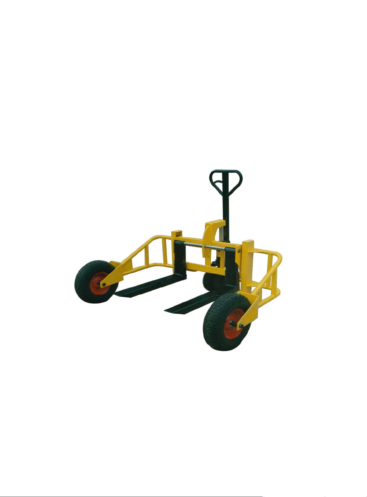
Thank you for purchasing a ALL-T-2 construction hand pallet truck. This top quality pallet
truck has been designed to travel over rough ground where no ordinary pallet truck can go.
Suitable for Nurseries, Builder’s Yards, Marinas and so on. Top quality hydraulic pump with
welded construction. Hard chrome plated piston and pump plunger ensure durability and
corrosion resistance. All the joints are fitted with seals to ensure sealing and keep the body
from oil leaking. Safety by-pass valve helps protect against overload. 3-position control
handle allows operator to lower, raise and engage pump into neutral position with a simple
tough of the lever. Strong & light tubular steel framing and adjustable fork width. The large
450mm pneumatic tyre wheels make handling pallets of most sizes possible without the
need for a forklift.
Specifications
Item Unit Size
Capacity lbs 2000
Fork length in 31-1/2
Fork width mm 4
Fork height mm 2-3/8
Distance of fork max. mm 27
Distance of fork min. mm 9-1/8
Lift height mm 3-1/8 - 9
Overall length mm 50
Overall width mm 64-1/2
Overall height mm 49
Dia. Of the front wheels/
Steering wheels
Weight lbs 326
mm Φ17-3/4/Φ11
2
Page 3
Safety Instructions
1. Keep feet out from underneath load.
2. Make sure load will not fall or tip before moving.
3. Do not operate loaded pallet truck on ramps or inclines.
4. Keep the load centered on the pallet.
5. Do not load pallet truck beyond rated capacity.
6. Always wear appropriate safety shoes.
Operating Pallet Truck
Pallet Truck Operation
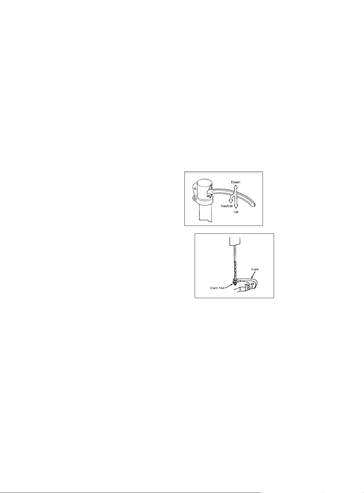
To raise the forks, place handle in the UP
position (bottom part of the handle slot), see
Fig. 1.
To lower forks, pull lever handle to DOWN
position (upper part of the slot).
To freely move the handle, set the lever in
Neutral (center notch of slot).
To Lift a Load
1. Lower forks to lowest position, Figure 1.
2. Insert forks under load, or into pallet.
3. Place lever in UP position (bottom part
of slot), Figure 1.
4. Move handle up, and down until forks
reach desired height.
To Move a Load
1. Place lever in NEUTRAL position (center
notch of slot), Figure 1.
2. Pull or push pallet truck to desired
location.
To Lower a Load
1. Pull lever to the DOWN position (upper part of slot), Figure 1.
2. Pull forks away from load.
Up-Down Cam Adjustment
1. Set the lever in the NEUTRAL position, Figure 1.
2. Turn the cam nut while pumping the handle, Figure 2.
3. When lifting stops, give the nut one more turn.
4. The cam nut is properly ad justed when pumping the handle in the NEUTRAL position
causes no movement of the hydraulic ram.
Cleaning the Release Valve (Bleed the Pump)
Over time, the hydraulic pump assembly may become clogged with debris, air bubbles, and
not function properly.
To clean the release valve and bleed the pump:
1. Pump handle quickly, raising pallet truck to full extent. While continuing pumping
action, pull lever to down position.
2. When forks reach total down position, valve is flushed. Repeat if necessary.
Fig. 1
Fig. 2
3
Page 4

Lubrication
Check the oil level annually by removing
the oil plug found on the top of the pump
housing. When changing or adding oil, fill
the tank through the oil plug screw hole to
80% capacity with hydraulic jack oil, about
2” deep in pump housing, see Figure 3.
Do not use any other type of oil.
There is one grease fitting (#55B in the
breakdown) located on the table.
Lubricate this point on a semi-annual basis.
Wheel bearings are sealed and require no lubrication. Crank Shaft features oil light
bushings that also require no lubrication. Lightly oil all moving parts.
Cleaning Relief Valve
Over time, relief valve may become clogged with debris and will not work properly. To clean
relief valve, flush out hydraulic system as follows:
Pump handle quickly, raising pallet truck to full extent and then quickly release pumping
action.
Lubricating and Oiling
When changing or adding oil, fill tank to 80% capacity (Figure 3) with hydraulic oil, such as:
Shell Tellus Oil--------No. 22 or 27, Turbine Oil------------No. 22, Texaco Regal ----------No. 32.
Change grease of rear and front wheels annually.
Fig. 3
Troubleshooting
Possible problems could arise in the operation of your hydraulic pallet truck. Their probable
cause(s) and corrective action(s) follow:
Condition Probable Cause Corrective Action
Hydraulic unit does not lift. Oil low in tank.
Steel ball not seated in hydraulic
unit.
Worn O-ring in ram cylinder
Once lifted, truck lowers by
itself.
Fork does not lower. Cam broken
Lever does not set at
NEUTRAL position.
Steel ball not seated in hydraulic
unit
Worn O-ring in ram cylinder
Relief valve not seated properly
Relief valve not adjusted properly
Oil leakage from each valve
Up-down cam nut out of
adjustment
Broken fork rods and linkage
Up-down cam nut out of
adjustment
Make sure there is no oil leakage
from valve, and add oil.
See “Cleaning Relief Valve” in this
manual.
Consult authorized repair station.
See “Cleaning Relief Valve” in this
manual.
See “Cleaning Relief Valve” in this
manual.
See “Cleaning Relief Valve” in this
manual.
Reload truck within load capacity,
and adjust valve by pressure
adjustment screw.
Tighten plug of each valve.
Replace cam chain.
Refer to Adjust Up-down Cam” in
this manual.
Replace broken parts.
Refer to “Adjusting Up-down Cam”
in this manual
4
Page 5

Spare Parts List
PART NO. DESCRIPTION PART DESCRIPTION
001 Handle 037 Ram Piston
002 Spring 038 Dust Seal
003 Roller Pin 039 O-ring 29.85x3.5
004 Bushing 1615 040 Back-Up Ring
005 Roller 041 Pump Housing Assembly
006 Bushing 1615 042 Oil Plug
007 Spring Pin 3x28 043 Spring
008 Handle Pin 044 Table Pin
009 E-ring 15 045 Bushing 1620
010 Plunger Piston 046 O-ring 4.8x1.9
011 Spring Cap 047 Release Nozzle
012 Spring 048 Cam
013 Dust Seal 049 Wheel Shaft
014 U-ring 18x24x8 050 Wheel
015 Spring Pin 3x28 051 Washer 16
016 Spring Pin 8x25 052 Nut M16
017 Spring Pin 8x45 053 Split Pin 4x30
018 Relief Plug 054 Shaft
019 O-ring 11.2x2.4 055 Mounting Plate
020 Pressure Adjust Screw 056 Shaft
021 Spring 057 Fork
022 Spring Base 058 Screw M6x35
023 Steel Ball 6 059 Guide Roller
024 Release Plug 060 Bushing 0808
025 Washer 061 Guide Roller Axle
026 Spring 062 Bearing 6206-Z
027 Spring 063 Rolling Axle Cover
028 Valve 064 Washer
029 Steel Ball 9 065 Front Wheel
030 Lever 066 Snap Ring 44
031 Release Rod 067 Master
032 Chain Joint 068 Dust Cover
033 Chain 069 Bearing Base
034 Anchor Bolt 070 Bearing 51109-Z
035 V-Nut M6 071 Table
036 Steel Ball 14 072 Bearing Seal
5
Page 6

EXPLODED VIEW OF CHPT CONSTRUCTION
HAND PALLET TRUCK
6
Page 7

Attaching the Tow Bar (ALL-TTB) to ALL-T-series Lift Trucks
A
y
C
B
Nylon hook strap
Hitch
end
6
Tow bar accessor
3
2
Step 1: Remove the drive wheels to expose the wheel shaft.
A
Drive
wheels
FIG. 1: Front View of Fully Assembled Shed &
Parts List
6
1
7
Steering Shaft
(not part of tow
bar assembly)
4
5
Truck
connection
end
LL-T lift truck
Item
no.
Description Quantity
1 7/16in. – 14 x 2.5in. bolt 2
2 5/8in. – 11 x 3.5in. bolt 1
3 1/2in. – 13 x 1in. 2
4 7/16in. – 14 nylock nut 2
5 5/8in. – 11 nylock nut 1
6 1/2in. – 13 nylock nut 2
7 1/4in. – 20 x 3in. bolt 2
8 1/4in. – 20 nylock nut 2
Remove the lug nut
and lock washer
that fastens each
drive wheel to the
wheel shaft.
steering
shaft
wheel shaft
Slide the wheels off of the wheel shaft.
Page 8

p
a
t
: Locate the shaft retaining pin; then remove it.
Step 2
D. Locate the wheel shaft retaining pin,
which is identified with an arrow in photo D at
left. The retaining pin fixes the wheel shaft in
place, so that it cannot rotate or slide.
E. Before the wheel shaft can be removed,
the retaining pin must be removed. Tap the
retaining pin out of its channel as shown in
hoto E.
D
steering shaft
E
retaining pin
shaft retaining pin
: Remove the wheel shaft, position the tow bar around the steering shaft and then reinstall the wheel shaft.
Step 3
F. Tap and pull the wheel shaft out of its channel through the drive shaft (see
photo A below).
G. Position the connection end (see Fig. 1, p. 1) of the tow bar around the
steering shaft and align all of the shaft openings; then insert the wheel shaft.
F G
: Remove the cross-link that connects the two sides of the tow bar with a flat blade screwdriver and a 1/4in.crescen
Step 4
wrench
I. Remove the bolt
and nut that fix the
cross-link in place,
and then remove
the cross-link.
H
I
Page 9

K
: Fix the wheel shaft in place.
Step 5
J
J. Rotate the
wheel shaft
until the hole
for the retaining
pin aligns with
the opening in
the steering
shaft; then tap
the retaining
pin into place.
K. Reinstall the
cross-link and
tighten the
fasteners.
: Reconnect the wheels to the wheel shaft, by reversing the procedure described in Step 1 on p. 1.
Step 6
: For storage purposes, a nylon strap is included in the tow bar accessory kit. Photos L and M below indicate one
Step 7
possible method of using the strap to secure the tow bar in an upright (storage) orientation.
L M
 Loading...