

Vestil A-LIFT User Manual
rev. 1/16/2013 A-Lift, manual.doc
y
VESTIL MANUFACTURING CORP.
2999 North Wayne Street, P.O. Box 507, Angola, IN 46703
Telephone: (260) 665-7586 -or- Toll Free (800) 348-0868
Fax: (260) 665-1339
www.vestilmfg.com e-mail:
HUsales@vestil.comU
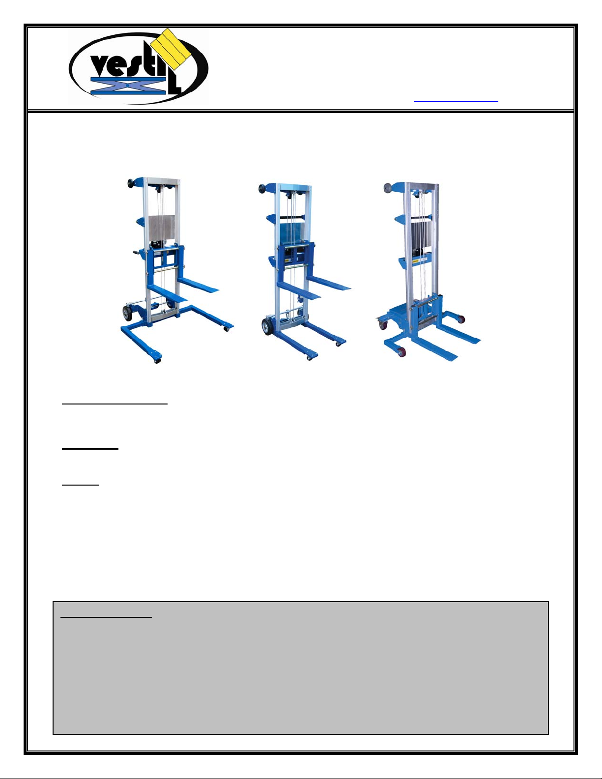
A-LIFT SERIES HAND WINCH LIFT TRUCKS
INSTRUCTION MANUAL
A-LIFT-S
UReceiving instructionsU:
A-LIFT-R A-LIFT-CB
After delivery, IMMEDIATELY remove the packaging from the Hook-Base in a manner that preserves the
packaging and maintains the orientation of the product in the packaging; then inspect the product closely to
determine whether it sustained damage during transport. If damage is discovered during the inspection,
UimmediatelyU record a complete description of the damage on the bill of lading. If the product is
undamaged, discard the packaging.
UNOTESU:
1) Compliance with laws, regulations, codes, and non-voluntary standards enforced in the location where the
product is used is exclusively the responsibility of the owner/end-user.
2) VESTIL is not liable for any injury or property damage that occurs as a consequence of failing to apply
either:
a) Instructions in this manual; or
b) Information provided on labels affixed to the product. Neither is Vestil responsible for any consequential
damages sustained as a result of failing to exercise sound judgment while assembling, installing, using or
maintaining this product.
UTable of Contents
Hazard identification: explanation of signal words………………………………………………………………… 2
Safety Guidelines…………………………………………………………………………………………………….. 2
Product specifications by model……………………..……………………………………………………………… 3
FIG 1A: HP & EHP models have telescoping mast frame……………………………………………………….. 3
FIG. 1B: Diagram of Assembled A-Lift……………………………………………………………………………... 4
Assembly Instructions…………………………………………………………………… …………………………… 5-7
Operation Instructions……………………………………………………………………………… ………………… 7-9
Inspections & Maintenance…………………………………………………………….......................................... 10
Label placement diagram………………………………………………………… …………………………………. 11
Limited warrant
……………………………………………………………………………………………………….12
Copyright 2012 Vestil Manufacturing Corp. Page 1 of 12
rev. 1/16/2013 A-Lift, manual.doc
Hazard Identification: Explanation of SIGNAL WORDS
This manual uses SIGNAL WORDS to indicate the likelihood of personal injuries, as well as the probable
seriousness of those injuries, if the product is misused in the ways described. Other signal words call attention to uses
of the product likely cause property damage.
The signal words used appear below along with the meaning of each word:
Identifies a hazardous situation which, if not avoided, UWILLU result in
DEATH or SERIOUS INJURY. Use of this signal word is limited to the
Identifies a hazardous situation which, if not avoided, COULD result in
Indicates a hazardous situation which, if not avoided, COULD result in
Identifies practices likely to result in product/property damage, such as
Each person who assembles, installs, uses, or maintains this product should read the entire manual in advance
and fully understand the directions. If after reading the manual you do not understand an instruction, ask
your supervisor or employer for clarification, because failure to adhere to the directions in this manual
might result in serious personal injury.
SAFETY GUIDELINES
Vestil diligently strives to identify foreseeable hazards associated with the use of its products. However, no manual
can address every conceivable risk. The end-user ultimately is responsible for exercising sound judgment at all times.
most extreme situations.
DEATH or SERIOUS INJURY.
MINOR or MODERATE injury.
operation that might damage the product.
Electrocution might result if any part of the mezzanine ladder contacts electrified wires. Reduce the
likelihood of electrocution by applying common sense:
Electrocution Risk: DO NOT contact electrical wires with the winch lift or load! Be aware of all overhead
obstacles and take precautions to avoid contact with them.
If this product is used improperly or carelessly, the operator and/or bystanders might sustain serious
personal injuries or even be killed. ALWAYS use the product properly:
Failure to read and understand the entire manual before assembling, installing, using or servicing the
product Uconstitutes misuseU. Read the manual to refresh your understanding of proper use and maintenance
procedures.
ALWAYS inspect the Lifter before each use according to the inspection instructions on p. 10. DO NOT use the
Lifter unless it passes the inspection.
Prior to each use, ALWAYS inspect the area where you intend to use the lifter. Inspect the area for unusual
conditions that might require special precautions. See “Notice” on p. 7-8.
DO NOT use a malfunctioning lifter. Always perform the “Function Test” described in the Notice on p. 8 before each
use.
Regardless of whether the lifter is loaded or unloaded, DO NOT stand or travel under the forks and DO NOT allow
any other person to stand or travel under the forks.
Inform all persons in the area that you are going to use the Lifter, and instruct them to stay clear of the device and
the supported load during operation.
ALWAYS make sure that your clothing and body do not contact the mast structure, lifting mechanisms, or carriage
during operation. ONLY operate the lifter from the “Operator’s Position,” shown in Step 2 on p. 8. DO NOT move the
lifter or raise or lower the forks unless you are in the operator’s position.
DO NOT allow people to ride the lifter.
ALWAYS load the A-lift according to the list of recommendations that appears below. Failure to properly position a
load on the forks (or platform) might cause the lifter to tip over and you could be injured as a consequence.
1. DO NOT exceed the A-Lift’s maximum rated load. The rated load (capacity) of your Lifter is posted on a
product label as shown in “Label placement diagram” on p. 11.
2. ONLY move loads using the forks or the optional deck platform (“load-engaging means”).
3. DO NOT handle off-center loads or loads that cannot be centered. ALWAYS properly center the load.
4. Start and stop gradually to avoid upsetting the load from the forks/platform.
5. NEVER tilt the lifter while carrying a load. All four castors must maintain contact with the ground when a
load is on the forks/platform.
DO NOT modify the ladder in any way UNLESS you UfirstU obtain written approval from Vestil. Unauthorized
modifications automatically void the limited warranty (see p. 12) and might make the table unsafe to use.
Copyright 2012 Vestil Manufacturing Corp. Page 2 of 12
rev. 1/16/2013 A-Lift, manual.doc
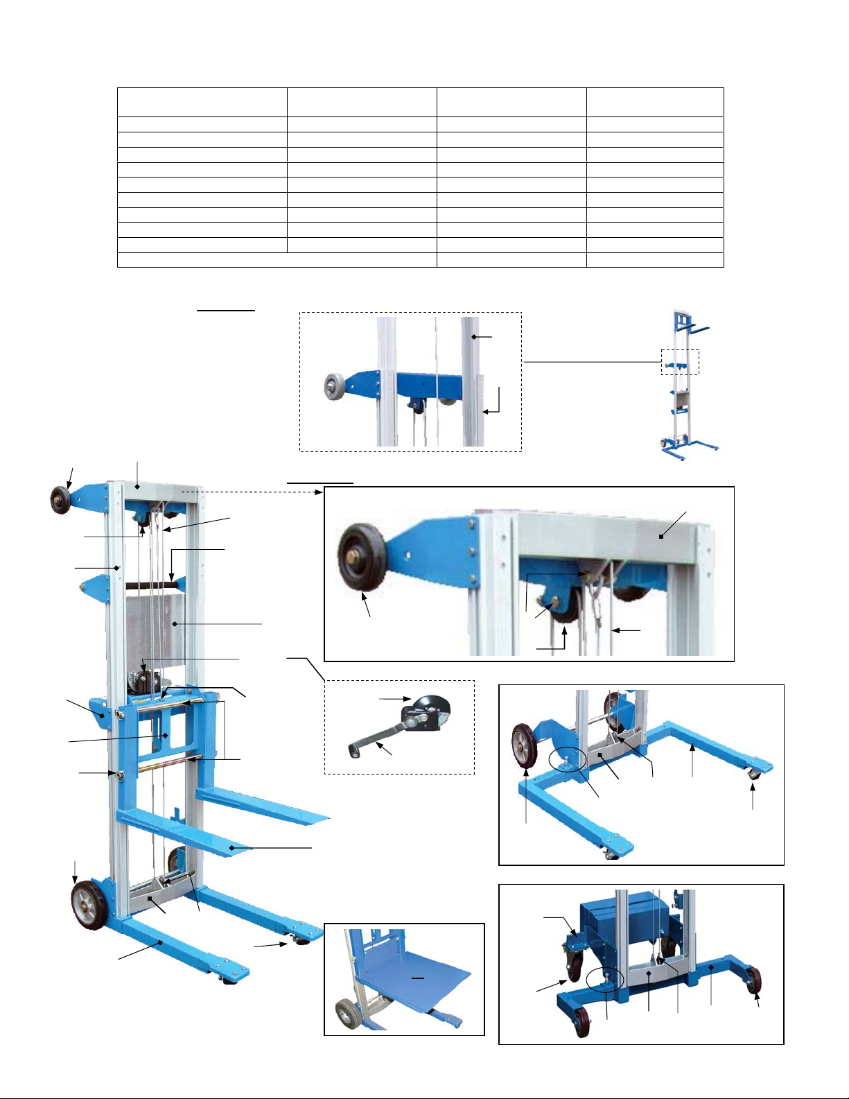
Product Specifications by Model:
Model
A-Lift-R 24 x 35 x 68 500 (~227kg) 136 (~62kg)
A-Lift-R-HP 24 x 35 x 68 400 (~182kg) 140 (~64kg)
A-Lift-S 29 x 43 x 68 500 (~227kg) 140 (~64kg)
A-Lift-S-HP 29 x 43 x 68 400 (~182kg) 145 (~66kg)
A-Lift-S-EHP 29 x 43 x 79 350 (~159kg) 154 (~70kg)
A-Lift-CB 29 x 47 x 68 500 (~227kg) 396 (~180kg)
A-Lift-CB-HP 29 x 47 x 68 400 (~182kg) 418 (~190kg)
A-Lift-CB-EHP 29 x 47 x 79 350 (~159kg) 449 (~204kg)
A-Lift-DK (Deck Platform) 20-1/2 x 24-1/4 25 (~11kg)
A-Lift-PN: 10in. pneumatic rear wheels 20 (~9kg)
UFIG. 1AU: HP & EHP models have telescoping mast frame
Overall Size in Inches
3
2
UFIG. 1BU: Diagram of Assembled A-Lift
(W x L x H)
Maximum Rated
Load in Pounds
6
7
Net Weight in
Pounds (~kg)
4 & 4a
7
26
10
25
23
5
1
8
27
(Winch)
33 & 33a
11
12
2
27
27a
14 4a
4a
4
14 4a
15
9 or 23
or 30
20
3
5
-S Models
13
16
-CB Models
22
Copyright 2012 Vestil Manufacturing Corp. Page 3 of 12
21
29
19
15
14
4a
18
17
rev. 1/16/2013 A-Lift, manual.doc
A
Parts List
“Standard Units” refers to A-Lift-R, -S, & -CB models; “HP Units” means A-Lift-R-HP, -S-HP, and -CB-HP models; “EHP
Units” indicates A-Lift-S-EHP and –CB-EHP models.
Diagram
Number Description
1 Operator Handle A-Lift-1 1 17 4 inch Fixed Wheel A-Lift-CB-17 2
2 Loading Wheels A-Lift-2 2 18 Adjustable Leg (-CB
3 Upper Inner Frame Pulley
(casting)
4
4a
10 Carriage A-Lift-10 1 26 Winch Mounting Bracket A-Lift-26 1
11 Fork Mounting Tube A-Lift-11 2 27
12 Fork A-Lift-12 2 28 Not Available nNA N/A
13 Adjustable Leg (Straddle
14
15 Leg Lock Pin A-Lift-CB-15 2 31-32 Not Available N/A N/A
16 Caster: either 2in. (option A)
Large Pulley
Large cable anchor bolt &
nut
5
Cable (Standard Units)
Cable (HP Units)
Cable (EHP Units)
6 Telescoping Inner Mast
Frame (only HP & EHP
Units)
7 Mast Frame A-Lift-7 1 23 Solid Rubber Wheel A-Lift-23 2
8 Decal Plate A-Lift-8 1 24 Brake (optional) A-Lift-24 1
9 10 in. Pneumatic wheel
(optional)
base)
Lower Inner Frame Pulley
(casting)
or 2½ in. (option B)
Part
Number Quantity
A-Lift-3 1 19 5 inch Swivel Castor A-Lift-CB-19 2
A-Lift-4
A-Lift-4a
A-Lift-5
A-Lift-HP-5
A-Lift-EHP-5
A-Lift-6 1 22 Legs - Standard base (R
A-Lift-9 2 25 Fork Lock Pin A-Lift-25 4
A-Lift-S-13 2 29 Deck Platform (optional) A-Lift-Deck 1
A-Lift-14 1 30 [-S models with 4-point
A-Lift-S-16 2 33
Diagram
Number Description
counterweight base
models)
3 20 Counterweight Base A-Lift-CB-20 1
1 21 Caster: 2in. double wheel A-Lift-R-21 2
models)
27a
27-SPG
33a
Winch
Winch Handle
Winch Spring
casters]
4in. caster – option A
5in. caster – option B
Small pulley
Cmall Cable Anchor Bolt &
Nut
Part
Number Quantity
A-Lift-CB-18 2
A-Lift-R-22 2
A-Lift-27
A-Lift-27a
-Lift-27-SPG
A-Lift-29A
A-Lift-29B
A-Lift-33
A-Lift-33a
1
1
1
1
1
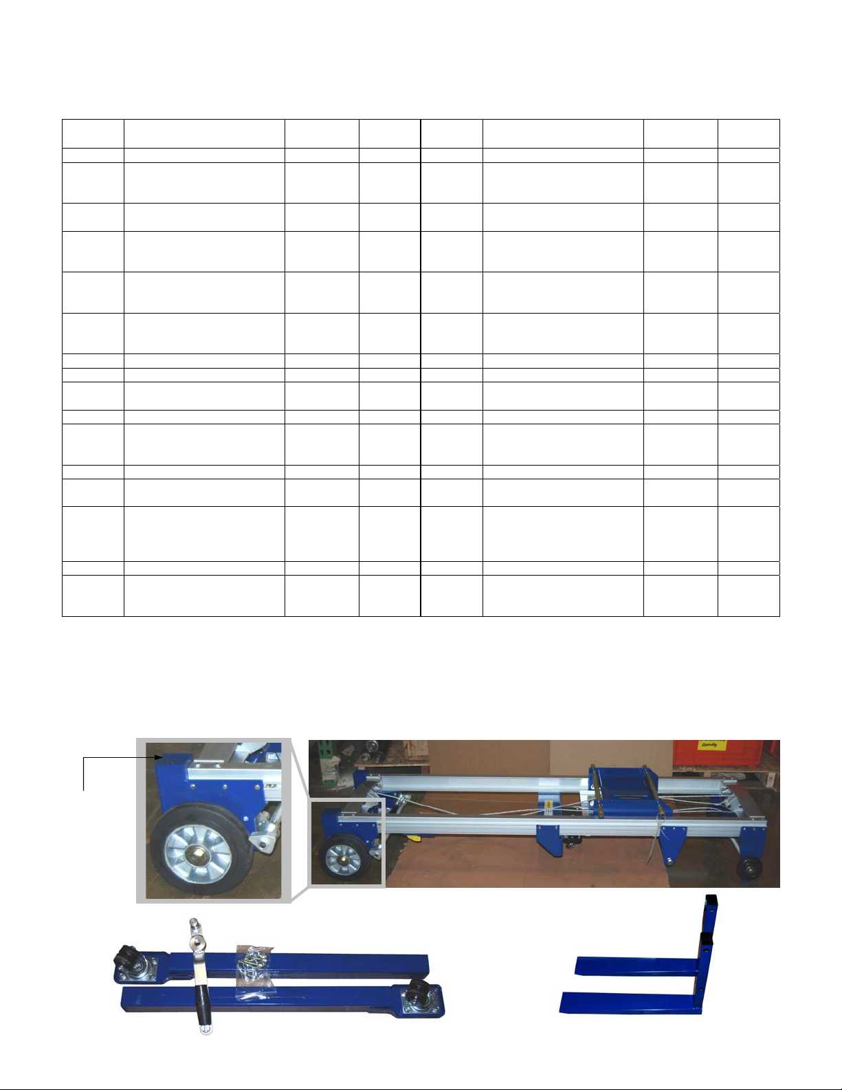
Assembly Instructions
Vestil ships winch lifts to its customers in a mostly assembled form. The minimal assembly that is required differs by
model, so follow the directions that correspond to your lifter.
If you purchased an A-Lift-R or A-Lift-S, you will receive 3 pieces:
1). Main Assembly
Support leg
openings
2). Box 1 contains: standard support legs (2),
fork retaining pins (4), winch handle (1).
U
Copyright 2012 Vestil Manufacturing Corp. Page 4 of 12
3). Box 2 contains:
forks (2).
 Loading...