

Vestil AHLT Series Owner's Manual
VESTIL MANUFACTURING CORP.
2999 North Wayne St., Angola, IN 46703
Ph: 260-665-9521 Fax: 260-665-1339
Website: www.vestil.com
Ergonomic Solutions
Contents
Safety Precautions .......................................... 1
Operation .................................................. 1 & 4
Installation Instructions.................................... 2
Pneumatic/Hydaulic Circuit Diagrams.............. 3
Loading Instructions ........................................ 4
Pneumatic/Hydraulic Diagram ......................... 5
Revised 11-13
A company dedicated to solving ergonomic
and material handling problems since 1955.
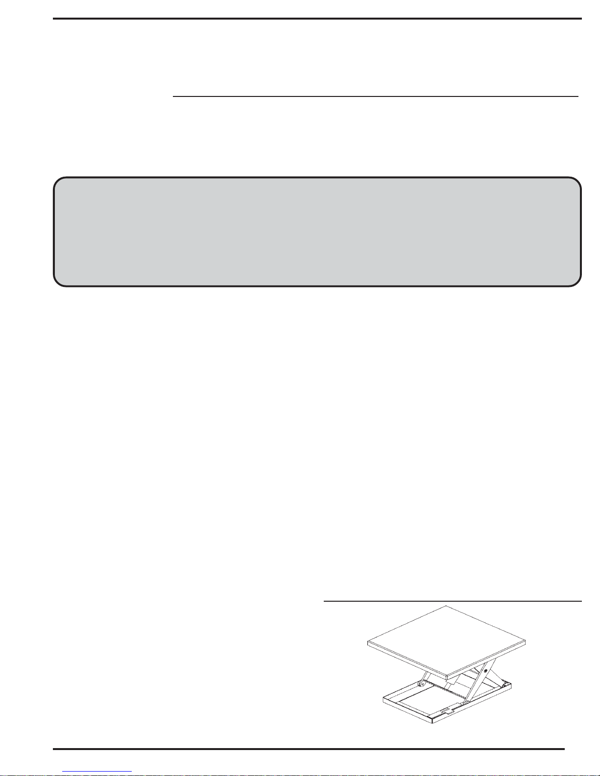
OWNER'S MANUAL
AHLT-SERIES
AIR HYDRAULIC SCISSOR TABLES
Exploded Parts Drawing ............................... 6
Parts List....................................................... 7
Troubleshooting Guide ........................... 8 & 9
Inspections & Maintenance ........................ 10
Label placement diagram............................ 11
Limited Warranty ......................................... 12
SAFETY GUIDELINES:
Material handling is dangerous. To reduce the
likelihood of injury to person or property:
•Read this manual in its entirety before installing,
using and maintaining this table for the first time!
•The capacity of your table is based on a uniformly
distributed, centered load. DO NOT exceed the
capacity because permanent damage and/or personnel
injury could result. Contact the factory for side-loading
and end-loading capacities.
•DO NOT lower the unit onto the maintenance prop(s)
while the table is loaded.
•DO NOT go under the platform unless the
maintenance prop is in position.
•ONLY use AW-32 hydraulic oil (or equivalent), or
Dexron II transmission fluid in the tables reservoir. Do
not use brake fluids or jack oils.
•Check the settings and conditions of all safety
switches and stickers frequently.
•Never operate the table if it (or any component) is
in need of repair. Tag the unit "Out-of-service" and
notify maintenance personnel if, during operation, any
unusual noises, movements, or noticeable damage to
the understructure of controls, or if the table fails to
respond normally to control commands.
RECEIVING INSTRUCTIONS:
After delivery, IMMEDIATELY remove the packaging
from the product in a manner that preserves the
packaging and maintains the orientation of the product
in the packaging; then inspect the product closely to
determine whether it sustained damage during
transport. If damage is discovered during the inspection,
immediately record a complete description of the
damage on the bill of lading. If the product is
undamaged, discard the packaging.
NOTES:
1) Compliance with laws, regulations, codes, and nonvoluntary standards enforced in the location where the
product is used is exclusively the responsibility of the
owner/end-user.
2) VESTIL is not liable for any injury or property damage
that occurs as a consequence of failing to apply either:
a) the instructions in this manual; or b) information
provided on labels affixed to the product. Neither is
Vestil responsible for any consequential damages
sustained as a result of failing to exercise sound
judgment while assembling, installing, using or
maintaining this product
OPERATION
The table is equipped with a "dead man"
style push
button controler. This type of operation,
also called "push-to- run", allows the operator to
move the deck of the table as much or as little as
necessary.
The air motor of the power unit requires a
minimum air supply of 70 CFM at 70 PSI.
AIR HYDRAULIC SCISSOR TABLE MODEL AHLT
1

INSTALLATION INSTRUCTIONS
Review this Owner's Manual in its entirety before beginning the installation.
The following tools are required to install the table:
- A fork truck or hoisting means.
- Lag bolts, masonry drill, ma
sonry bit, wrench for lag bolt, grout, and steel shims.
INSTALLATION PROCEDURE
1) Read each label applied to the table (see "Label placement diagram" on p. 11). Confirm that every
label shown in the diagram is present.
2) Move the table to the desired installation location. Support the base of the table while moving it.
3) Be sure maintenance prop is in place before getting under platform.
4) If mounting the power unit externally, blow out the connecting hydraulic line with compressed air.
5) Install the lift table on a level, even surface.
a) Anchor the table to the floor with appropriately-matched anchor bolts.
b) Measure the diameter of the bolt holes in the base of the frame, and install bolts that are at
least 4in. long to anchor the table to the floor.
c) Shim the table to level it. Grout under the base of the table to provide additional resistance
to warping and bending forces applied to the base between shims. Grout around the entire
perimeter of the base frame.
6) Connect main air supply to the control pedestal. If no control pedestal is supplied, see schematic
for air inlet. NOTE: Use only clean, dry air. Use of a filter/regulator is recommended.
7) Operate the table through a few RAISE-LOWER cycles (fully raise the deck and then lower
it completely according to the instructions on p. 3); then check the oil level. Add oil if necessary
[see Oil specifications on p. 10 (under "Yearly") of this manual].
2

Hydraulic Circuit & Component Operation
To raise the deck of the table, press the "RAISE" button of the hand controller. This opens the air motor
supply valve and flowing air turns the hydraulic pump. Oil from the reservoir moves through the suction filter
and into the pump. From the pump, pressurized oil flows through the check valve and then enters the
cylinders.
The function of the check valve is to restrict oil flow to one direction, i.e. towards the cylinders. It
prevents oil from flowing back into the pump circuit when the pump stops running. This traps oil in the
cylinders and maintains the desired elevation of the deck.
If the weight of a load on the table exceeds the capacity of your table, then although the "RAISE"
button might be pressed the deck cannot ascend. Instead, pressure builds in the circuit between the pump
and the cylinders. This pressure causes the "ball" (or "poppet") in the relief valve to unseat and directs the
pump output to the reservoir through the return pipe rather than to the cylinders.
To lower the deck, press the "LOWER" control button. This opens a hydraulic dump valve. The
poppet in the solenoid valve unseats and oil flows from the cylinders through the flow control valve, return
filter, solenoid valve, and the oil return pipe to the reservoir.
The flow control valve controls the lowering speed of the table. It is preset and cannot be changed.
Releasing the "LOWER" control button deenergizes the solenoid and closes the valve poppet. This
prevents oil from returning to the reservoir and consequently the cylinders stop retracting. The deck will
maintain its elevation.
Cartridge Valves
The lowering valve, as discussed above, is of cartridge construction and is virtually maintenance free.
If a malfunction occurs, refer to the trouble shooting section.
To clean the cartridge valve:
1.) Use a thin tool to push the poppet in from the bottom to open the valve.
2.)
3.)
4.)
Velocity Fuse
There is a brass velocity fuse with a stainless steel spring in the base of each cylinder. The fuse is a
safety feature that activates if a pump failure occurs. If the pump were to fail, the deck would lower much
more rapidly. However, as soon as the descent speed exceeds a preset threshold speed, the velocity fuse
closes and prevents oil from flowing. When the fuse shuts, the platform stops lowering and maintains
position until hydrualic pressure is reestablished. This safety feature reduces the likelihood of personal
injury or property damage as a result of pump failure. To reset the velocity fuse, briefly activate the pump by
pressing the "RAISE" button.
Repeat several times while valve is immersed in kerosene or mineral spirits. Blow the valve
dry.
Inspect O-rings and the polytetrafluoroethylene (PTFE) extrusion washer.
Reinstall the valve. Tighten the valve in its seat to approximately 30 ft-lb.
3

LOADING INSTRUCTIONS
SAFETY INSTRUCTIONS TO THE OPERATOR
The load capacity, which appears on the
data label (see p. 11, label 287) of your unit, is the
net maximum weight the table will support. All
loads applied to the table must be centered and
evenly distributed, and assumes the load is
centered. DO NOT exceed the capacity because
permanent damage or injury might occur.
OPERATING INSTRUCTIONS
This unit is equipped with a constant
pressure ("deadman" type) push button controller.
The buttons are marked, "RAISE" and "LOWER".
Press the "RAISE" button to elevate the deck of
the table. When the button is pressed, the
motor air supply valve opens and air pressure
causes the cylinder to extend. Cylinder extension
raises the deck. Always stand to the side of the
table while operating the cylinder and keep clear
of moving parts. The platform will rise as long as
the "RAISE" control is pressed. When the button is
released, the deck will maintain its present
position. Releasing the button allows the valve to
close and prevents further air flow, i.e. closes the
pilot-operated motor air supply valve.
Pressing the "LOWER" control button
energizes the lowering solenoid valve. This allows
the cylinders to retract as oil returns to the
reservoir. As with the RAISE button, releasing the
LOWER button causes the deck to stop moving
and to maintain its current elevation. Be certain
no person or object is in the way while the unit
descends.
Always center and evenly distribute loads
1.)
placed on the table.
2.)
DO NOT use the table if repairs are necessary.
Only use the table if it is in normal operating
condition.
fy
3.) Tag the unit "Out of service" and
noti
maintenance personnel if you notice anything
unusual during operation, such as binding,
odd pump noises, etc.
Do not continue to press the "UP" control if
4.)
the unit does not elevate. The motor and/or
pump might be permanently damaged as a
consequence.
ORDERING REPLACEMENT OR EXTRA PARTS
Vestil Manufacturing Co. company is
commit
products.
equipment failure that results from the use of
unapproved replacement parts. To order
replacement (or spare) parts contact
Service at the telephone number of email address
published on the cover page of theis manual. To
expedite your request, be prepared with the serial
number of your table, which appears on the data
label (#287 on p. 11). Only refer to part numbers
listed in this Owner's Manual.
ted to using high quality parts in all of our
Vestil is not responsible for any
Customer
If the unit is overloaded, the deck will not
rise. Instead, the relief valve will open due to
excessive pressure buildup ans oil will bypass the
cylinder and flow into the reservoir.
Always remember: 1) the motor operates only
while the "RAISE" button is pressed; and 2) the
lowering solenoid valve is energized only while the
"LOWER" button is pressed.
4
 Loading...