

Page 1
VESTIL MANUFACTURING CORP.
2999 North Wayne St., Angola, IN 46703
Ph: 260-665-9521 Fax: 260-665-1339
Website: www.vestil.com
Ergonomic Solutions
Contents
Safety Precautions .......................................... 1
Operation .................................................. 1 & 4
Installation Instructions.................................... 2
Hydaulic Circuit ............................................... 3
Loading Instructions ........................................ 4
Pneumatic/Hydraulic Diagram ......................... 5
Revised 03-00
A company dedicated to solving ergonomic and material
handling problems since 1955
.
OWNER'S
MANUAL
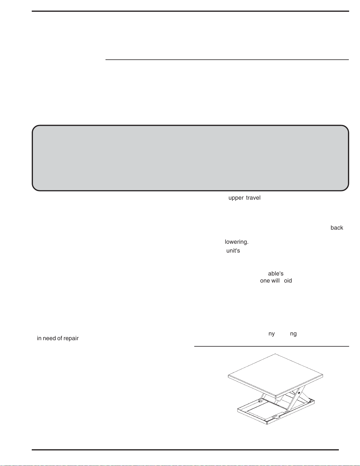
AIR HYDRAULIC SCISSOR TABLE
MODEL AHLT
Exploded Parts Drawing ............................... 6
Parts List....................................................... 7
Troubleshooting Guide ........................... 8 & 9
Maintenance & Safety ................................ 10
Warning Label Identification ....................... 11
Warranty ..................................................... 12
SAFETY PRECAUTIONS
Read owner's manual completely before operating unit! The
model number and capacity of the table is incribed on its
(green or red) nameplate. Please remember to include these
numbers with any correspondence with your dealer or factory.
Have only qualified personnel perform maintenance and repairs
on this unit.
• The lifting capacity of your unit is based on a uniformly
centered load. This capacity should never be exceeded,
as permanent damage and/or personnel injury could result.
Consult the factory for side or end loading capacities.
• Never lower the unit onto the safety maintenance prop
while the table is loaded. Never go under the platform
unless the maintenance prop is in position.
• Use AW-32 hydraulic oil (or equivalent), or Dexron II
transmission fluid in the tables reservoir. Do not use brake
fluids or jack oils.
• Check the setting and conditions of all safety switches and
stickers frequently.
• Never operate the table if it or any of its components are
in need of repair. Notify the appropriate personnel in the
event of any unusual noises, movements, or noticeable
damage to the table's understructure of controls, or if the
table doesn't respond normally to its controls.
upper travel upper travel setpoint, and air valve is closed
which in turn disables the pilot-operated motor air supply valve
and causes the unit to stop.
The "LOWER" control opens a hydraulic "dump"
valve to allow that same oil in the cylinder(s) to return back to
the reservoir. When the unit has completely lowered it will
simply stop lowering.
• The power unit's air motor requires a minimum air supply
of 70 CFM at 70 PSI.
• A good quality air filter/lubricator is required for proper,
long-term operation of the table's power unit. Operation
of this machine without one will void the warranty!
• Refer to the hydraulic troubleshooting guide if problems
arise with the table's operation.
• Regular inspections should be performed on all
pneumatic and hydraulic hoses, as will as a visual
inspection of all structural members, hinges and
components. Check for cracking or scraped paint, oil
leaks, noticeable wear at any pivoting points, loose or
missing fastners and components, etc.
OPERATION
The table is furnished with a remote "deadman" style
control. This type of operation, also called "push to run", allows
the operator to move the unit as much or as little as necessary.
Each press of the air control valves opens a seperate pilotoperated valve to initaiate the desired movement, and
movement is creased when the valve is released.
The "RAISE" control opens the motor air supply valve
to run the power unit and thereby pump hydraulic fluid to the
cylinder(s). When the table raises to the previously determined
AIR HYDRAULIC SCISSOR TABLE
MODEL AHLT
1
Page 2

INSTALLATION INSTRUCTIONS
Review Complete Owner's Manual Before Commencing Installation.
For installation you will need the following:
1.) A fork truck or hoisting means.
2.) Lag bolts, masonry drill, masonry bit, wrench for lag bolt, grout, and steel shims.
Move the lift with straps or forks under frame.
Read all the warning labels on the lift and be sure all of the labels are on the lift.
Check local codes pertaining to your application.
If the power unit is to be mounted externally, be sure to blow out the connecting hydraulic line with
compressed air.
Be sure maintenance prop is in place before getting under platform.
After anchoring to floor, shim or grout the full length on the frame sides.
The entire length of the frame sides must be supported.
Operate lift through a few cycles. Check and add oil if necessary. See oil specification elsewhere
in this manual.
Clean up any debris or spilled oil.
2
Page 3

HYDRAULIC CIRCUIT
When the operator wants to raise the unit, he/she presses the "RAISE" button. This opens the
air motor supply valve which turns the hydraulic pump. Oil from the reservoir is drawn in through the
suction filter and into the pump. The pump delivers the pressurized oil through the check valve before
entering the cylinders.
The function of the check valve is to allow the oil to flow in one direction, i.e. towards the
cylinders. It also prevents the flow of oil back into the pump circuit when the pump stops running. This
holds the oil in the cylinders and maintains the desired elevation.
If the load is excessive, and the "RAISE" button is still depressed, pressure will build up in the
circuit between the pump and the cylinders. This forces the "ball" or "poppet" in the relief valve to
unseat allowing the pump out put returns into the reservoir through the return pipe.
When the operator wants to lower the unit, he presses the "LOWER" button. This opens a
hydraulic "DUMP" valve. The poppet in the solenoid valve is unseated and oil now returns from the
cylinders through the flow control valve, return filter, the solenoid valve, oil return pipe, and in the
reservoir.
The flow control valve controls the down speed of the table. It is preset and cannot be
changed.
Releasing the "LOWER" control will de-energize the solenoid, closing the valve poppet. This
prevents the oil from returning to the reservoir and the cylinders will stop retracting. The unit will
maintain that particular elevation.
Cartridge Valves
The lowering valve, as discussed above, is of cartridge construction and is virtually
maintenance free. If there is a faulty operation, check trouble shooting section. To clean the cartridge
valve, follow this procedure:
1.) Use a sharp object and push poppet in from the bottom to open the valve.
2.) Repeat several times while valve is immersed in kerosene or mineral spirits. Blow dry.
3.) Inspect "O" rings and the teflon extrusion washer.
4.) Reinstall. The valve should be tightened to approximately 30 ft. lbs.
Velocity Fuse
There is a brass velocity fuse with a stainless steel spring in the base of each cylinder. In the
event of a hydraulic pump failure, the platform starts to lower at a fast rate. As soon as the descent
speed exceeds the preset speed, the velocity fuse will shut off the oil flow and the platform will remain
stationary until pressure is reapplied. This safety feature reduces the possibility of accidental personal
injury or damage to the table or contents. To reset the velocity fuse just briefly activate pump by
depressing the "RAISE" button.
3
Page 4

LOADING INSTRUCTIONS
The load capacity rating as inscribed on the
nameplate of your unit designates the net capacity,
assuming the load is centered. This capacity must
never be exceeded, as permanent damage or injury
may result.
SAFETY INSTRUCTIONS TO THE OPERATOR
1.) Always load the unit properly.
2.) Never use the Lift if it is in need of
repairs or in the case of malfunction.
OPERATING INSTRUCTIONS
This unit is furnished with constant pressure
("deadman" type) push button controls. Depressing
the "RAISE" control opens ths motor air supply
valve. The cylinder begins to extend and the deck
starts to raise. Stand to the side when operating.
Stay clear of moving parts. The platform will rise as
long as the "RAISE" control is pressed.
On releasing the control, the unit will cease
to rise and will remain at that particular elevation.
This is because the pushbutton valve will close
which in turn closes the pilot-operated motor air
supply valve.
On pressing the "LOWER" control, the
lowering solenoid valve is energized. The cylinders
retract as the oil returns to the reservoir and, upon
releasing the control, the unit will cease to lower,
remaining at that particular elevation. Be certain no
person or object is in the way when the unit is
descending.
3.) Notify your maintenance personnel in case
you notice anything out of the ordinary,
such as binding, odd pump noises, etc.
4.) Do not continue to depress the "UP" control
if the unit is not raising. You can
permanently damage the motor or pump
by doing so.
ORDERING REPLACEMENT OR EXTRA PARTS
Our company takes pride in using the finest
available parts for our equipment. We are not
responsible for equipment failure resulting from the
use of unapproved replacement parts. To order
replacement or extra parts for your equipment
contact Customer Service at the factory. In any
correspondence with the factory please include the
serial number which is inscribed on the nameplate
of the piece of equipment. Use only the part numbers
provided in this Owner's Manual.
In the event the unit is overloaded, it will not
raise the relief valve will open due to excessive
pressure buildup, an oil will bypass into the reservoir.
Always remember that the motor runs only when the
"RAISE" button is depressed and the lowering
solenoid valve is energized only when the "LOWER"
button is pressed.
4
Page 5

PNEUMATIC/HYDRAULIC DIAGRAM
HYDRAULIIC LINE
AIR SUPPLY LINE
AIR PILOT LINE
NOTE: Operation of this machine without a filter/lubricator will void the warranty!
5
Page 6

AIR HYDRAULIC SCISSOR TABLE
MODEL AHLT
6
Page 7

ITEM
NUMBER
AIR HYDRAULIC SCISSOR TABLE
DESCRIPTION
MODEL AHLT
PART
NUMBER
QTY
1
2
3
4
4A
5
6
7
8
9
10
11
12
13
14
15
CYLINDER MOUNT SPRING PIN
CYLINDER MOUNT PIVOT PIN
CYLINDER MOUNT BEARING
HYDRAULIC CYLINDER
CYLINDER SEAL KIT (NOT PICTURED)
ROLLER PIN
ROLLER
ROLLER BEARING
ROLLER WASHER
ROLLER SNAP RING
HINGE PIN
HINGE PIN BEARING
PIVOT PIN GREASE ZERK
PIVOT PIN BEARING
PIVOT PIN ROLL PIN
PIVOT PIN
ST-SPRGPIN
ST-CYLPIN
ST-CYLBRG
ST-CYL
ST-CYLSLKT
ST-RLPIN
ST-RLR
ST-RLRBRG
ST-RLRWSHR
ST-RLRNRG
ST-HNGPIN
ST-HNGBRG
ST-GRSZRK
ST-PVTBRG
ST-PPRP
ST-PVTPIN
1
1
2
1
1
4
4
4
4
4
4
4
2
2
2
2
16
17
18
19
20
21
22
23
**PLEASE SUPPLY SERIAL NUMBER AT TIME OF ORDER**
PIVOT PIN WASHER
TOE GUARD HANGER NUT
TOE GUARD HANGER WASHER
TOE GUARD CORNER PIECE
TOE GUARD ALUMINUM RAIL
TOE GUARD SWITCH
TOE GUARD SWITCH RETAINING SCREW
SAFETY STOP BLOCK
ST-PVTPIN
ST-HNGRNUT
ST-HNGRWSH
ST-TGRDCNR
ST-TGRDRAIL
ST-TGRDSW
ST-TGRDSCR
ST-STBLK
2
4
4
4
4
2
4
1
7
Page 8

HYDRAULIC EQUIPMENT
Trouble Shooting Quick Reference Guide
(For further information contact the factory)
****BEFORE PREFORMING ANY MAINTENANCE WORK ALWAYS INSTALL MAINTENANCE SAFETY BLOCKS****
Observation Possible Cause Remedy
1.) Table does not raise but pump is running
a. Hose or hydraulic line is leaking.
b. Fluid level in reservoir is low.
c. Load exceeds capacity requirements. Relief Valve is
bypassing the fluid back into the reservoir.
d. Suction filter is clogged, starving pump.
e. Suction line may be leaking air, due to loose fittings.
f. Filler/Breather cap on tank may be clogged.
c. Correct as necessary.
d. Add fluid. Refer to Owner's Manual for proper fluid
levels.
e. DO NOT CHANGE RELIEF VALVE SETTING.
Instead, reduce the load to rated capacity.
f. Remove and clean.
g. Inspect all fittings for proper fit.
h. Remove and clean.
2.) Table raises too slowly.
3.) Motor labors, or is excessively hot.
4.) "Spongy" or "Jerky" table operation. Do not
confuse spongy operation with small surges caused by
foreign material on table wheel roller plate.
5.) Table lowers too slowly when loaded.
g. Lowering Valve may be energized by faulty wiring or
stuck open.
h. Hydraulic pump may be inoperative.
a. Foreign material stuck in lowering solenoid, causing
some fluid to bypass back into tank.
b. Foreign material clogging suction filter, breather cap,
or a pinched hose.
d. Table overloaded.
e. Pump is inoperative.
a. Oil starvation causes pump to bind. High internal
heat is developed. If this occurs, pump may be
permanently damaged.
b. Binding cylinders.
a. Fluid starvation.
b. Air in system.
a. Down Valve filter clogged.
b. Pinched tube or hose.
c. Foreign material in flow control valve.
d. Binding cylinders
e. Foreign material in velocity fuse.
i. Remove solenoid valve. Check and clean. (Refer to
Hydraulic Section of Owner's Manual).
j. Disconnect hydraulic line at power unit. Put pressure
line in a large container and cycle pump. If no output,
check the pump motor coupline, which may be
defective, and correct as necessary. If pump is worn,
consult factory for replacement parts service.
a. Lower the platform. Remove the solenoid valve and
clean. (Refer to Hydraulic Section of Owner's Manual).
b. Correct as necessary. (See also, 1(f), (h).
d. See 1(e).
e. See 1(j).
a. See 1(d), (f), (g), (h), (j).
b. Align cylinders correctly.
a. See 1(d), (f), (g), (j).
b. See air bleed procedure p.9.
a. Remove solenoid valve and clean filter.
b. Correct as necessary. (In case of pipe, check for
obstruction in line.)
c. Remove and clean Flow Control Valve. (Refer to
Hydraulic Section of Owner's Manual).
d. Align cylinders correctly.
e. Remove and clean velocity fuse. (Refer to Hydraulic
Section of Owner's Manual.)
8
Page 9

Observation Possible Cause Remedy
6.) Table lowers too quickly.
7.) Table raises then lowers slowly.
8.) Table has raised, but does not lower.
a. Leaking hoses and/or cracked fittings.
b. Check valve is stuck open. (The combination of a
stuck Check Valve and open Soleniod Valve will cause
excessive speeds.)
c. Foreign material stuck in Flow Control Valve. (In this
case, table lowers initially at a normal rate then speeds
up as the platform descends.)
a. Down Solenoid Valve may be incorrectly wired or is
stuck open due to dirt.
b. Check Valve may be stuck open.
c. Check for leaking hoses, fittings, pipes.
d. Cylinder packings may be worn or damaged.
a. Down Solenoid Valve is stuck.
b. Faulty Down Solenoid Coil.
c. Maintenance safety bar, or some other object
blocking down trave.
d. Binding cylinders.
e. In case of excessive down speeds, the Velocity
Fuse will become operative and shut off the oil flow
from the cylinders, thus the platform will remain
stationary.
f. Check if the Limit Switch is inoperative and
the platform has raised all the way so that the
mechanical stops are engaged. If mechanical stops are
engaged, the Velocity Fuse has been locked up.
a. Correct as necessary.
b. Remove and clean Check Valve. (Refer to Hydraulic
Section of Owner's Manual ).
c. Remove Flow Control Valve from the Valve Block
and clean. (Refer to Hydraulic Section of Owner's
Manual).
a. See 2(a).
b. Remove and clean Check Valve. (Refer to
Hydraulic Section of Owner's Manual ).
c. Correct as necessary.
d. Replace packings. (Consult Factory for replacement
parts.)
a. Lightly tap down the Solenoid Coil body to seat it
properly. (DO NOT hit coil hard as it will permanently
damage the internal stem). DO NOT remove the
Solenoid Valve from the Block as the unit will come
down at a dangerous speed.
b. Remove and replace. (Refer to Electrical Section of
Owner's Manual.)
c. Raise table and remove the safety bar, or whatever
object is blocking the down travel, then press the down
button.
d. See 2(e).
e. To unlock, re-pressurize the hydraulic system.
f. Refer to Velocity Fuse Section of the Owner's
Manual
Notes:
9
Page 10

Routine Maintenance & Safety
Raise the table and install the maintenance safety prop before beginning any
inspection or work on the unit.
(A) Before Each Use Check For The Following:
1.) Frayed wires
2.) Oil leaks
3.) Pinched or chafed hoses
4.) Structural deformation of arms, frame, and platform
5.) Unusual noise or binding
Do not use if there are any of the above!
(B) Monthly Inspections
1.) Check oil level. Oil should be 1" to 1-1/2" below the top of the tank with the lift in
the fully lowered position. Add as necessary.
2.) Check for oil leaks. See trouble shooting section and correct as necessary.
3.) Check roller bushings, axle pin, clevis and pivot points for wear.
4.) Check for worn or damaged hydraulic hoses. Repair as necessary.
5.) Check rollers for looseness and wear. See trouble shooting.
6.) Check retaining rings at all axles, pivot points and clevis.
7.) Check for unusual noise. See trouble shooting.
8.) Make sure all warning labels are in place and in good condition.
9.) Clean off dirt and debris.
(C) Yearly
Oil reservoir should be changed at least once a year, or sooner if the oil darkens or
becomes gritty. Presence of water is indicated if the oil turns milky. Recommended oil:
AW-32 Hydraulic fluid or equal.
10
All maintenance work must be preformed by qualified personnel with training in the
repair of electrical and hydraulic components.
Page 11

WARNING LABEL IDENTIFICATION
MAKE SURE ALL WARNING LABELS ARE IN PLACE!
6
1
5
1
SERIAL NUMBER
*Product safety signs or labels
should be periodically inspected
and cleaned by the product users
as necessary to maintain good legibility for safe viewing distance . . .
ANSI 535.4 (10.21)
Contact manufacturer for replacement labels if needed.
WARNING
!
SECURE FRAME
TO FLOOR
AVISO
!
ASEGURE EL
BASTIDOR AL PISO
AVERTISSEMENT
!
FIXER SOLIDEMENT
LE CADRE AU PLANCHER
204
1
ON HYDRAULIC TANK (NOT SHOWN)
2
5
ISO AW-32
HYDRAULIC OIL OR EQUIVALENT
ACEITE HIDRÁULICO O EQUIVALENTE
HYDRAULIQUE OU ÉQUIVALENT
FOUND ON HANDLE
3
PLATFORM MUST BE LOWERED BEFORE MOVING LIFT
LA PLATAFORMA DEBE DE SER BAJADA ANTES DE
MOVER EL MONTACARGAS
LA PLATE-FORME DOIT ÊTRE ABAISSÉE AVANT
D’ACTIVER LE MONTE CHARGE
206
210
6
DANGER
!
PELIGRO
!
ATTENTION
!
5
BOTH SIDES & FRONT END
! WARNING ! AVISO
PINCH POINT
TO AVOID PERSONAL INJURY READ
OWNER’S MANUAL BEFORE OPERATING
OR REPAIRING SCISSOR LIFT
PARA EVITAR DAÑOS PERSONALES
LEA EL MANUAL DEL PROPIETARIO
ANTES DE OPERAR O REPARAR EL
ELEVADOR DE TIJERAS
POUR ÉVITER TOUTE BLESSURE
PERSONNELLE LIRE LE MANUEL DU
PROPRIÉTAIRE AVANT DE METTRE EN
MARCHE OU AVANT DE RÉPARER
L’ÉLEVATEUR CISEAU
4
KEEP CLEAR OF
DO NOT PUT HANDS, FEET OR
OBJECTS UNDER TOP. LOWER
PLATFORM SLOWLY.
NO PONGA MANOS, PIES U
OBJECTOS DEBAJO DEL
BORDE. DESCIENDA LA
PLATAFORMA LENTAMENTE.
NE PAS METTRE LES MAINS,
LES PIEDS OU TOUT OBJET
SOUS LE PLATEAU SUPÉRIEUR.
DESCENDRE LA PLATFORM
LENTEMENT
FOR USER INSTRUCTIONS OR QUESTIONS CONTACT
PARA INSTRUCCIONES DE USO Ó CONSULTAS CONTACTAR
POUR INSTRUCTIONS OU QUESTIONS SUPPLÉMENTAIRES CONTACTER
T & S EQUIPMENT CO. • P.O. BOX 496 ANGOLA, IN 46703 • 1-800-348-0860 OR 219-665-9521
! AVERTISSEMENT
MANTENGASE ALEJADO DE
PUNTO DE CORTE
DO NOT WORK UNDER LIFT WITHOUT SAFETY
BLOCK OR WHILE LOADED. KEEP CLEAR OF
MOVING SCISSOR LEG MECHANISM.
NO TRABAJE DEBAJO DEL ELEVADOR SIN LOS
FRENOS DE SEGURIDAD O CUANDO ESTÉ
CARGADO. MANTENGASE ALEJADO DEL
MECANISMO DE TIJERA EN MOVIMIENTO.
NE PAS TRAVAILLER SOUS L’ÉLEVATEUR SANS
BLOCS DE SECURITÉ OU LORSQU’ IL EST
CHARGÉ. RESTER À L’ÉCART DU MÉCANISME
CISEAU LORSQUE L’ÉLEVATEUR EST EN
FONCTIONNEMENT.
SE TENIR À DISTANCE DU
POINT DE PINCEMENT
DO NOT STAND,
SIT OR
RIDE ON LIFT
NO SE SIENTE, SE
PARE,O VIAJE
EN EL ELEVADOR
NE PAS SE TENIR
DEBOUT,
S’ASSEOIR OU
MONTER SUR
L’ÉLEVATEUR
205
208
207
11
Page 12

LIMITED WARRANTY
ONE YEAR LIMITED WARRANTY. The manufacturer warrants for the original purchaser against
defects in materials and workmanship under normal use one year after date of purchase. (Not to exceed
15 months after date of manufacture.) Airbag is warrantied for 1 year or half a million cycles, whichever
comes first. Any part which is determined by the manufacturer to be defective in material or workmanship
and returned to the factory, shipping costs prepaid, will be, as the exclusive remedy, repaired or replaced
at our option. Labor costs for warranty repairs and/or modifications are not covered unless done at
manufacturer’s facilities. Any modifications performed without written approval of the manufacturer may
void warranty. This limited warranty gives purchaser specific legal rights which vary from state to state.
LIMITATION OF LIABILITY. To the extent allowable under applicable law, the manufacturer’s
liability for consequential and incidental damages is expressly disclaimed.
The manufacturer’s liability in any event is limited to, and shall not exceed, the purchase price paid.
Misuse or modification may void warranty.
WARRANTY DISCLAIMER. Our company has made a diligent effort to illustrate and describe the
products shown accurately; however, such illustrations and descriptions are for the sole purpose of
identification, and do not express or imply a warranty that the products are merchantable, or fit for a
particular purpose, or that the products will necessarily conform to the illustrations or descriptions.
The provisions of the warranty shall be construed and enforced in accordance with the UNIFORM
COMMERCIAL CODE and laws as enacted in the State of Indiana.
DISPOSITION. Our company will make a good faith effort for prompt correction or other adjustment
with respect to any product which proves to be defective within the Limited Warranty. Warranty claims must
be made in writing within said year.
SERVICE RECORD
DATE OF SERVICE:_____/_____/_____
WORK DONE BY:______________________________
SERVICE PERFORMED:__________________________________
_______________________________________________________
_______________________________________________________
DATE OF SERVICE:_____/_____/_____
WORK DONE BY:______________________________
SERVICE PERFORMED:__________________________________
_______________________________________________________
_______________________________________________________
DATE OF SERVICE:_____/_____/_____
WORK DONE BY:______________________________
SERVICE PERFORMED:__________________________________
_______________________________________________________
_______________________________________________________
DATE OF SERVICE:_____/_____/_____
WORK DONE BY:______________________________
SERVICE PERFORMED:__________________________________
_______________________________________________________
_______________________________________________________
DATE OF SERVICE:_____/_____/_____
WORK DONE BY:______________________________
SERVICE PERFORMED:__________________________________
_______________________________________________________
_______________________________________________________
Copyright T&S Equipment Company 2000
12
DATE OF SERVICE:_____/_____/_____
WORK DONE BY:______________________________
SERVICE PERFORMED:__________________________________
_______________________________________________________
_______________________________________________________
 Loading...