

Page 1
AHA manual 1111 rev. 12/5/2012
ALUMINUM ADJUSTABLE-HEIGHT GANTRY CRANE
INSTRUCTION MANUAL
VESTIL MANUFACTURING CORP.
2999 NORTH WAYNE STREET, P.O. BOX 507, ANGOLA, IN 46703
TELEPHONE: (260) 665-7586 -OR- TOLL FREE (800) 348-0868
FAX: (260) 665-1339
URL: WWW.VESTILMFG.COM EMAIL: SALES@VESTIL.COM
UUUNOTEUUU: Compliance with statues, regulations, and codes enforced in the location where the product is used is
exclusively the responsibility of the end user. Compliance with any “Standard” published by non-governmental
groups like ANSI, CSA, or ISO is entirely voluntary, unless incorporated by reference or reproduced in law or
regulation.
Table of Contents Table of Figures
Product Introduction……………………. 2 Fig. 1 AHA-2-8-8, 2-8-10, & 2-8-12 exploded parts diagram………………….. 5
Safety Principles……………………....... 4 Fig. 2 AHA-2-10-8, 2-10-10, & 2-10-12 exploded parts diagram……………… 6
Safety Guidelines……………………….. 4 Fig. 3 AHA-2-12-8, 2-12-10, & 2-12-12 exploded parts diagram……………… 7
Assembly Instructions………………….. 17 – 21 Fig. 4 AHA-2-15-8, 2-15-10, & 2-15-12 exploded parts diagram……………… 8
Use Instructions & Proper Loading…… 21 Fig. 5 AHA-4-8-8, 4-8-10, & 4-8-12 exploded parts diagram………………….. 9
Festoon Kit (option).…………………… 22 Fig. 6 AHA-4-10-8, 4-10-10, & 4-10-12 exploded parts diagram……………… 10
Inspections & Maintenance …………… 23 Fig. 7 AHA-4-12-8, 4-12-10, & 4-12-12 exploded parts diagram……………… 11
Label Placement Diagram …………….. 24 Fig. 8 AHA-4-15-8, 4-15-10, & 4-15-12 exploded parts diagram……………… 12
Limited Warranty……………………….. 25 Fig. 9 AHA-6-8-8, 6-8-10, & 6-8-12 exploded parts diagram………………….. 13
Fig. 10 AHA-6-10-8, 6-10-10, & 6-10-12 exploded parts diagram……………. 14
Fig. 11 AHA-6-12-8, 6-12-10, & 6-12-12 exploded parts diagram……………. 15
Fig. 12 AHA-6-15-8, 6-15-10, & 6-15-12 exploded parts diagram……………. 16
Copyright 2011 Vestil Manufacturing Corp.
Page 2

PRODUCT INTRODUCTION
Thank you for purchasing an Aluminum Adjustable-Height gantry crane (“crane,” “gantry crane,” or simply “AHA”).
Each AHA conforms to generalized performance specifications disclosed in this manual, and fulfills our demanding
standards for quality, safety and durability. Although operation and assembly are relatively intuitive, all persons who might
participate in assembly, use or maintenance of this crane must familiarize themselves with the instructions provided in this
manual.
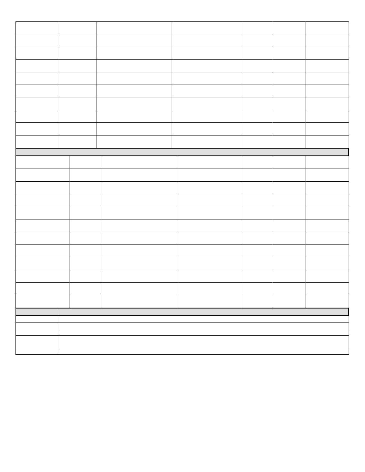
Each of the AHA-series variants listed below is distinguishable by load rating, beam length, and vertical travel range.
Specifications for each variant appear in the table below:
Model
AHA-2-8-8
AHA-2-8-10
AHA-2-8-12
AHA-2-10-8
AHA-2-10-10
AHA-2-10-12
AHA-2-12-8
AHA-2-12-10
AHA-2-12-12
AHA-2-15-8
AHA-2-15-10
AHA-2-15-12
AHA-4-8-8
AHA-4-8-10
AHA-4-8-12
AHA-4-10-8
AHA-4-10-10
AHA-4-10-12
AHA-4-12-8
AHA-4-12-10
AHA-4-12-12
AHA-4-15-8
AHA-4-15-10
AHA-4-15-12
AHA-6-8-8
AHA-6-8-10
Load Rating
(Capacity)
in Pounds
(kg)
2,000
(~909kg)
2,000
(~909kg)
2,000
(~909kg)
2,000
(~909kg)
2,000
(~909kg)
2,000
(~909kg)
2,000
(~909kg)
2,000
(~909kg)
2,000
(~909kg)
2,000
(~909kg)
2,000
(~909kg)
2,000
(~909kg)
4,000
(~1818kg)
4,000
(~1818kg)
4,000
(~1818kg)
4,000
(~1818kg)
4,000
(~1818kg)
4,000
(~1818kg)
4,000
(~1818kg)
4,000
(~1818kg)
4,000
(~1818kg)
4,000
(~1818kg)
4,000
(~1818kg)
4,000
(~1818kg)
6,000
(~2727kg)
6,000
(~2727kg)
Overall Beam Length &
Height in Feet and Inches
(meters & centimeters)
8ft.(L) 6in. (H)
2m 59cm (L) 15.2cm (H)
8ft.(L) 6in. (H)
2m 59cm (L) 15.2cm (H)
8ft.(L) 6in. (H)
2m 59cm (L) 15.2cm (H)
10ft. (L) 6in. (H)
3m 5cm (L) 15.2cm (H)
10ft. (L) 6in. (H)
3m 5cm (L) 15.2cm (H)
10ft. (L) 6in. (H)
3m 5cm (L) 15.2cm (H)
12ft. (L) 8in. (H)
3m 66cm (L) 20.3cm (H)
12ft. (L) 8in. (H)
3m 66cm (L) 20.3cm (H)
12ft. (L) 8in. (H)
3m 66cm (L) 20.3cm (H)
15ft. (L) 8in. (H)
4m 57cm (L) 20.3cm (H)
15ft. (L) 8in. (H)
4m 57cm (L) 20.3cm (H)
15ft. (L) 8in. (H)
4m 57cm (L) 20.3cm (H)
8ft. (L) 8in. (H)
2m44cm (L) 20.3cm (H)
8ft. (L) 8in. (H)
2m44cm (L) 20.3cm (H)
8ft. (L) 8in. (H)
2m44cm (L) 20.3cm (H)
10ft. (L) 8in. (H)
3m 5cm (L) 20.3cm (H)
10ft. (L) 8in. (H)
3m 5cm (L) 20.3cm (H)
10ft. (L) 8in. (H)
3m 5cm (L) 20.3cm (H)
12ft. (L) 8in. (H)
3m 66cm (L) 20.3cm (H)
12ft. (L) 8in. (H)
3m 66cm (L) 20.3cm (H)
12ft. (L) 8in. (H)
3m 66cm (L) 20.3cm (H)
15ft. (L) 10in. (H)
4m 57cm (L) 25.4cm (H)
15ft. (L) 10in. (H)
4m 57cm (L) 25.4cm (H)
15ft. (L) 10in. (H)
4m 57cm (L) 25.4cm (H)
8ft. (L) 10in. (H)
2m 44cm (L) 25.4cm (H)
8ft. (L) 10in. (H)
2m 44cm (L) 25.4cm (H)
Vertical Travel Range in
Feet and Inches
(meters and
centimeters)
5ft. 8in. to 8ft. 2in.
1m 73cm to 2m 49cm
7ft. 8in. to 10ft. 2in.
2m 34cm to 3m 10cm
9ft. 6in. to 12ft.
2m 90cm to 3m 66cm
5ft. 8in. to 8ft. 2in.
1m 73cm to 2m 49cm
7ft. 8in. to 10ft. 2in.
2m 34cm to 3m 10cm
9ft. 6in. to 12ft.
2m 90cm to 3m 66cm
5ft. 8in. to 8ft. 2in.
1m 73cm to 2m 49cm
7ft. 8in. to 10ft. 2in.
2m 34cm to 3m 10cm
9ft. 6in. to 12ft.
2m 90cm to 3m 66cm
5ft. 8in. to 8ft. 2in.
1m 73cm to 2m 49cm
7ft. 8in. to 10ft. 2in.
2m 34cm to 3m 10cm
9ft. 6in. to 12ft.
2m 90cm to 3m 66cm
5ft. 8in. to 8ft. 2in.
1m 73cm to 2m 49cm
7ft. 8in. to 10ft. 2in.
2m 34cm to 3m 10cm
9ft. 6in. to 12ft.
2m 90cm to 3m 66cm
5ft. 8in. to 8ft. 2in.
1m 73cm to 2m 49cm
7ft. 8in. to 10ft. 2in.
2m 34cm to 3m 10cm
9ft. 6in. to 12ft.
2m 90cm to 3m 66cm
5ft. 8in. to 8ft. 2in.
1m 73cm to 2m 49cm
7ft. 8in. to 10ft. 2in.
2m 34cm to 3m 10cm
9ft. 6in. to 12ft.
2m 90cm to 3m 66cm
5ft. 8in. to 8ft. 2in.
1m 73cm to 2m 49cm
7ft. 8in. to 10ft. 2in.
2m 34cm to 3m 10cm
9ft. 6in. to 12ft.
2m 90cm to 3m 66cm
6ft. 2in. to 8ft. 2in.
1m 88cm to 2m 49cm
8ft. 2in. to 10ft. 2in.
2m 49cm to 3m 10cm
Base
Width in
Inches
(cm)
54in.
(~137cm)
54in.
(~137cm)
54in.
(~137cm)
54in.
(~137cm)
54in.
(~137cm)
54in.
(~137cm)
54in.
(~137cm)
54in.
(~137cm)
54in.
(~137cm)
54in.
(~137cm)
54in.
(~137cm)
54in.
(~137cm)
54in.
(~137cm)
54in.
(~137cm)
54in.
(~137cm)
54in.
(~137cm)
54in.
(~137cm)
54in.
(~137cm)
54in.
(~137cm)
54in.
(~137cm)
54in.
(~137cm)
54in.
(~137cm)
54in.
(~137cm)
54in.
(~137cm)
65in.
(~165cm)
65in.
(~165cm)
Flange
Width in
Inches
(cm)
3.31in.
(~8.41cm)
3.31in.
(~8.41cm)
3.31in.
(~8.41cm)
3.31in.
(~8.41cm)
3.31in.
(~8.41cm)
3.31in.
(~8.41cm)
4in.
(~10.2cm)
4in.
(~10.2cm)
4in.
(~10.2cm)
4.17in.
(~10.6cm)
4.17in.
(~10.6cm)
4.17in.
(~10.6cm)
4in.
(~10.2cm)
4in.
(~10.2cm)
4in.
(~10.2cm)
4.17in.
(~10.6cm)
4.17in.
(~10.6cm)
4.17in.
(~10.6cm)
4.17in.
(~10.6cm)
4.17in.
(~10.6cm)
4.17in.
(~10.6cm)
4.66in.
(~11.8cm)
4.66in.
(~11.8cm)
4.66in.
(~11.8cm)
4.66in.
(~11.8cm)
4.66in.
(~11.8cm)
Net Weight in
Pounds (kg)
271
(~123kg)
280
(~127kg)
295
(~134kg)
283
(~129kg)
294
(~134kg)
310
(~141kg)
303
(~138kg)
325
(~148kg)
340
(~155kg)
353
(~160kg)
364
(~166kg)
373
(~170kg)
324
(~147kg)
360
(~164kg)
375
(~170kg)
388
(~176kg)
405
(~184kg)
431
(~196kg)
352
(~160kg)
421
(~191kg)
446
(~203kg)
475
(~216kg)
498
(~226kg)
519
(~236kg)
474
(~215kg)
510
(~232kg)
Copyright 2011 Vestil Manufacturing Corp. Page 2 of 25
Page 3
AHA-6-8-12
AHA-6-10-8
AHA-6-10-10
AHA-6-10-12
AHA-6-12-8
AHA-6-12-10
AHA-6-12-12
AHA-6-15-8
AHA-6-15-10
AHA-6-15-12
6,000
(~2727kg)
6,000
(~2727kg)
6,000
(~2727kg)
6,000
(~2727kg)
6,000
(~2727kg)
6,000
(~2727kg)
6,000
(~2727kg)
6,000
(~2727kg)
6,000
(~2727kg)
6,000
(~2727kg)
Adjustable Height Aluminum Gantry Cranes with Pneumatic Casters
AHA-15-8-8-PNU
AHA-15-8-10-PNU
AHA-15-8-12-PNU
AHA-15-10-8-PNU
AHA-15-10-10-PNU
AHA-15-10-12-PNU
AHA-15-12-8-PNU
AHA-15-12-10-PNU
AHA-15-12-12-PNU
AHA-15-15-8-PNU
AHA-15-15-10-PNU
AHA-15-15-12-PNU
1,500
(~682kg)
1,500
(~682kg)
1,500
(~682kg)
1,500
(~682kg)
1,500
(~682kg)
1,500
(~682kg)
1,500
(~682kg)
1,500
(~682kg)
1,500
(~682kg)
1,500
(~682kg)
1,500
(~682kg)
1,500
(~682kg)
AHA Option Description
AHA-2/4-TLC
AHA-PNU-RF
AHA-2/4-V
AHA-2/4-V4
AHA-KIT
TOTAL LOCKING CASTERS (SET OF 4; ONLY FOR 2,000 & 4,000LB. CAPACITY MODELS)
RETROFIT FOUR-WAY LOCKING PNEUMATIC CASTERS (1,500 POUND CAPACITY)
8IN. X 2IN. V-GROOVE WHEELS (SET OF 4; 2,000 & 4,000LB. CAPACITY MODELS ONLY)
8IN. X 2IN. V-GROOVE WHEELS (SET OF 4 WITH 4-POSITION LOCK; ONLY FOR 2,000 & 4,000LB. CAPACITY
MODELS)
(2) COME-ALONG FOR HEIGHT ADJUSTMENT ONLY
8ft. (L) 10in. (H)
2m 44cm (L) 25.4cm (H)
10ft. (L) 10in. (H)
3m 5cm (L) 25.4cm (H)
10ft. (L) 10in. (H)
3m 5cm (L) 25.4cm (H)
10ft. (L) 10in. (H)
3m 5cm (L) 25.4cm (H)
12ft. (L) 12in. (H)
3m 66cm (L) 30.5cm (H)
12ft. (L) 12in. (H)
3m 66cm (L) 30.5cm (H)
12ft. (L) 12in. (H)
3m 66cm (L) 30.5cm (H)
15ft. (L) 12in. (H)
4m 57cm (L) 30.5cm (H)
15ft. (L) 12in. (H)
4m 57cm (L) 30.5cm (H)
15ft. (L) 12in. (H)
4m 57cm (L) 30.5cm (H)
8ft. (L) 6in. (H)
2m 44cm (L) 15.2cm (H)
8ft. (L) 6in. (H)
2m 44cm (L) 15.2cm (H)
8ft. (L) 6in. (H)
2m 44cm (L) 15.2cm (H)
10ft. (L) 6in. (H)
3m 5cm (L) 15.2cm (H)
10ft. (L) 6in. (H)
3m 5cm (L) 15.2cm (H)
10ft. (L) 6in. (H)
3m 5cm (L) 15.2cm (H)
12ft. (L) 8in. (H)
3m 66cm (L) 20.3cm (H)
12ft. (L) 8in. (H)
3m 66cm (L) 20.3cm (H)
12ft. (L) 8in. (H)
3m 66cm (L) 20.3cm (H)
15ft. (L) 8in. (H)
4m 57cm (L) 20.3cm (H)
15ft. (L) 8in. (H)
4m 57cm (L) 20.3cm (H)
15ft. (L) 8in. (H)
4m 57cm (L) 20.3cm (H)
10ft. 2in. to 12ft. 2in.
3m 10cm to 3m 71cm
6ft. 2in. to 8ft. 2in.
1m 88cm to 2m 49cm
8ft. 2in. to 10ft. 2in.
2m 49cm to 3m 10cm
10ft. 2in. to 12ft. 2in.
3m 10cm to 3m 71cm
6ft. 2in. to 8ft. 2in.
1m 88cm to 2m 49cm
8ft. 2in. to 10ft. 2in.
2m 49cm to 3m 10cm
10ft. 2in. to 12ft. 2in.
3m 10cm to 3m 71cm
6ft. 2in. to 8ft. 2in.
1m 88cm to 2m 49cm
8ft. 2in. to 10ft. 2in.
2m 49cm to 3m 10cm
10ft. 2in. to 12ft. 2in.
3m 10cm to 3m 71cm
6ft. to 8ft. 6in.
1m 83cm to 15.2cm
8ft. to 10ft. 6in.
2m 44cm to 3m 20cm
9ft. 10in. to 12ft. 6in.
3m to 3m 81cm
6ft. to 8ft. 6in.
1m 83cm to 15.2cm
8ft. to 10ft. 6in.
2m 44cm to 3m 20cm
9ft. 10in. to 12ft. 6in.
3m to 3m 81cm
6ft. to 8ft. 6in.
1m 83cm to 15.2cm
8ft. to 10ft. 6in.
2m 44cm to 3m 20cm
9ft. 10in. to 12ft. 6in.
3m to 3m 81cm
6ft. to 8ft. 6in.
1m 83cm to 15.2cm
8ft. to 10ft. 6in.
2m 44cm to 3m 20cm
9ft. 10in. to 12ft. 6in.
3m to 3m 81cm
65in.
(~165cm)
65in.
(~165cm)
65in.
(~165cm)
65in.
(~165cm)
65in.
(~165cm)
65in.
(~165cm)
65in.
(~165cm)
65in.
(~165cm)
65in.
(~165cm)
65in.
(~165cm)
54in.
(~137cm)
54in.
(~137cm)
54in.
(~137cm)
54in.
(~137cm)
54in.
(~137cm)
54in.
(~137cm)
54in.
(~137cm)
54in.
(~137cm)
54in.
(~137cm)
54in.
(~137cm)
54in.
(~137cm)
54in.
(~137cm)
4.66in.
(~11.8cm)
4.66in.
(~11.8cm)
4.66in.
(~11.8cm)
4.66in.
(~11.8cm)
7in.
(~17.8cm)
7in.
(~17.8cm)
7in.
(~17.8cm)
7in.
(~17.8cm)
7in.
(~17.8cm)
7in.
(~17.8cm)
3.31in.
(~8.41cm)
3.31in.
(~8.41cm)
3.31in.
(~8.41cm)
3.31in.
(~8.41cm)
3.31in.
(~8.41cm)
3.31in.
(~8.41cm)
4.00in.
(~10.2cm)
4.00in.
(~10.2cm)
4.00in.
(~10.2cm)
4.17in.
(~10.6cm)
4.17in.
(~10.6cm)
4.17in.
(~10.6cm)
525
(~239kg)
538
(~245kg)
555
(~252kg)
581
(~264kg)
502
(~228kg)
571
(~260kg)
596
(~271kg)
605
(~275kg)
628
(~286kg)
649
(~295kg)
293
(~133kg)
297
(~135kg)
312
(~142kg)
300
(~136kg)
311
(~141kg)
327
(~149kg)
320
(~145kg)
342
(~156kg)
357
(~162kg)
370
(~168kg)
381
(~173kg)
390
(~177kg)
Copyright 2011 Vestil Manufacturing Corp. Page 3 of 25
Page 4
SAFETY PRINCIPLES
Vestil Manufacturing Corp. recognizes the critical importance of workplace safety. Employers are responsible for
instructing employees to use the product properly. UUUAny personUUU, who might foreseeably assemble, use, repair, or
perform maintenance on the crane, must read and understand every instruction BEFORE engaging in the activity.
Crane users should have access to the manual at all times and should review the directions as necessary. If you do
not understand an instruction, ask your supervisor or employer for clarification. Failure to adhere to the
directions in this manual might lead to serious personal injury or even death.
Although Vestil diligently strives to identify foreseeable hazardous situations, this manual cannot address every
conceivable danger. The end-user is ultimately responsible for exercising sound judgment at all times. Vestil is not liable
for any injury or property damage that occurs as a consequence of failing to apply the recommended maintenance and
use instructions that appear either in this manual or on labels affixed to the product.
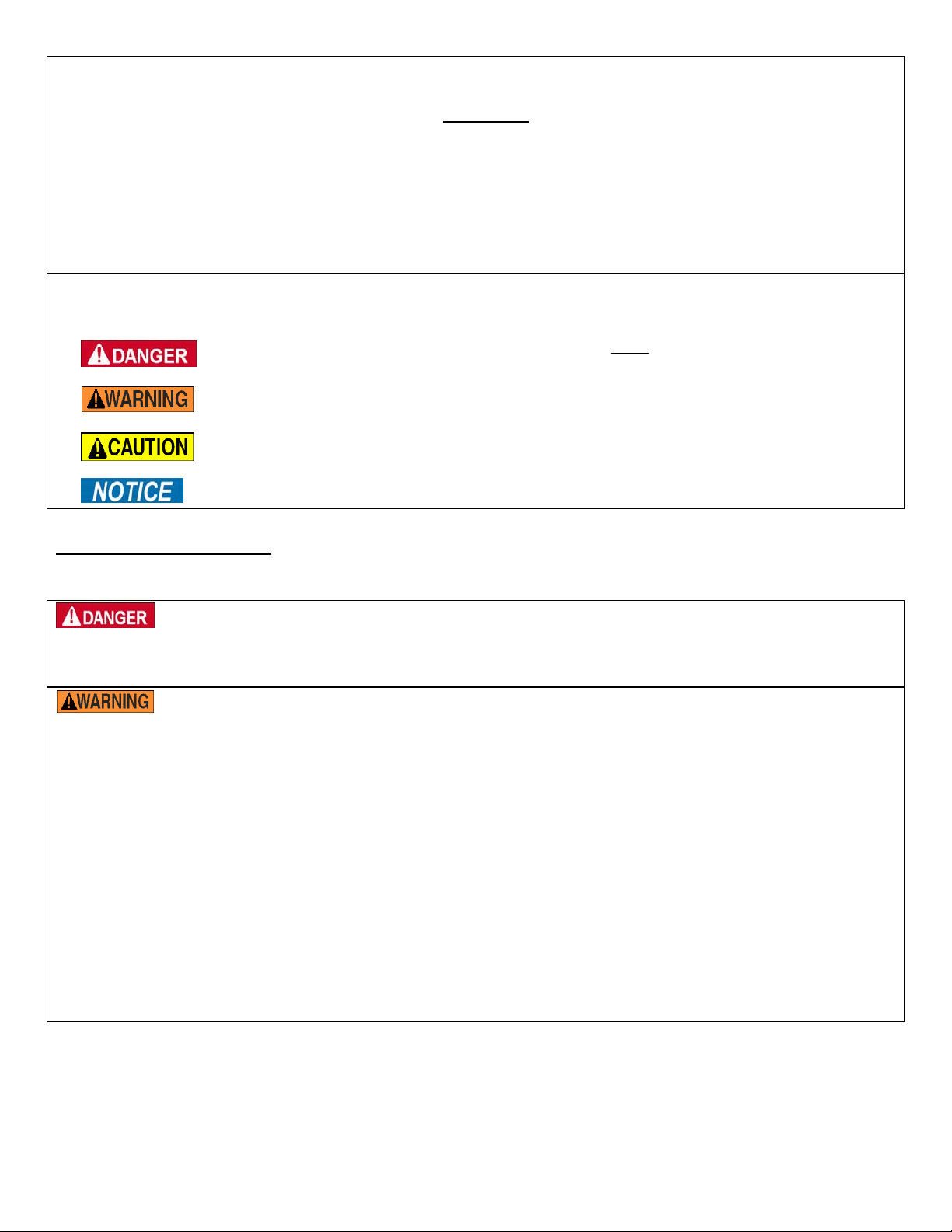
This manual classifies personal injury risks and situations that could lead to property damage with SIGNAL WORDS.
These signal words announce an associated safety message. The reader must understand that the signal word chosen
indicates the seriousness of the described hazard.
Identifies a hazardous situation which, if not avoided, UUUWILLUUU result in DEATH or SERIOUS
Identifies a hazardous situation which, if not avoided, COULD result in DEATH or
Indicates a hazardous situation which, if not avoided, COULD result in MINOR or
Identifies practices likely to result in product/property damage, such as operation that might
INJURY. Use of this signal word is limited to the most extreme situations.
SERIOUS INJURY.
MODERATE injury.
damage the crane.
UUUSAFETY GUIDELINES
Failure to read and understand the instructions included in this manual before using or maintaining the crane
constitutes misuse of the product.
Electrocution might result if the crane contacts electrified wires. Reduce the likelihood that an operator or
bystander might be electrocuted by applying common sense:
DO NOT assemble or use the crane in an area where it might contact electrified wires;
DO NOT contact electrified wires with the crane.
Material handling is dangerous. Improper or careless operation might result in serious personal injuries
sustained by crane user(s) or bystanders. Always apply the following:
Before using the crane, always inspect the usage area for conditions that might require special precautions.
DO NOT use a structurally damaged/malfunctioning crane. ALWAYS inspect the crane before each use according to the
inspection instructions on p. 22. DO NOT use the crane unless it passes every part of the prescribed inspection, i.e. do not use
the crane if it is damaged.
DO NOT attempt to lift a load that weighs more than the rated load of your crane model (see Table on p. 2-3; capacity labels
on product; label placement diagram on p. 23).
DO NOT stand beneath or travel under the crane if a load is suspended, and DO NOT permit any person to stand beneath
or travel under the load.
Inform all persons in the area that you are going to use the crane; instruct them to stay clear of the crane and the supported
load during operation.
DO NOT allow people to ride on the load or climb on the crane.
ALWAYS load the crane according to “Proper loading” recommendations on p. 21. Failure to properly load the crane might
cause the load to swing as it rises; a swinging load might cause serious injury to user(s) or others as a consequence.
DO NOT use the crane if any label (see p. 12) is unreadable, damaged, or absent. Contact Vestil for replacement label(s)
as needed.
DO NOT use the crane to transport loads; ONLY use the crane to lift loads!
Copyright 2011 Vestil Manufacturing Corp. Page 4 of 25
Page 5
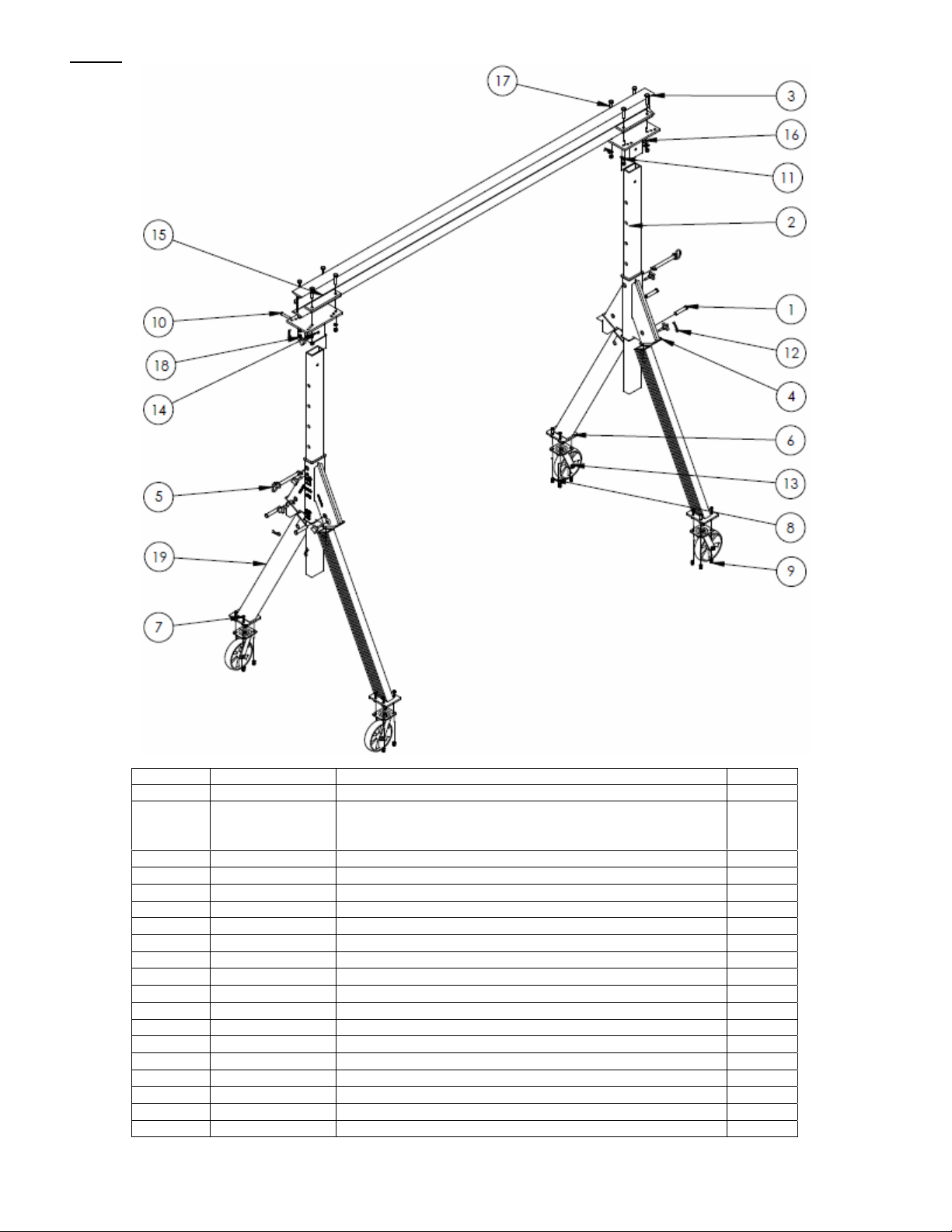
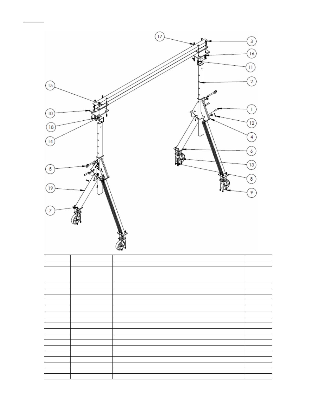
UUUFIG. 1UUU: Adjustable Height Aluminum Gantry Crane models AHA-2-8-8, AHA-2-8-10, & AHA-2-8-12
Item no. Part no. Description Quantity
1
2
3
4
5
6
7
8
9
10
11
12
13
14
15
16
17
18
19
33-112-034 ¾ in. x 3 3/4 in. clevis pin 4
28-014-228
28-014-191
28-014-192
AHA-2-8-8 telescoping tube, or
AHA-2-8-10 telescoping tube, or
AHA-2-8-12 telescoping tube
2
28-014-986-001 6in. I-beam extrusion 1
28-014-190 2,000lb.max. rated load aluminum casting 2
28-112-007 ¾ in. retaining pin 2
33082
11107
33622
36106
3
/8 in. zinc-plated SAE flat washer 16
3
/8 in. – 16 x 1¼ in. HHCS #2 zinc-plated bolt 16
3
/8 in. zinc-plated lock washer 16
3
/8 in. – 16 zinc-plated hex nut 16
28-112-029 ½ in. x 3in. zinc-plated retaining clevis pin 2
33626 ½ in. zinc-plated lock washer 8
45286
3
/8 in. x 25/8 in. #11 Hitch pin clip 6
16-132-249 GFN-8/2-S 4-way swivel lock caster 4
28-524-013 Top end cap weldment frame 2
28-516-054 I-beam clamp weldment 4
08-025-007 Knob 8
19213-B ½ in. – 12 x 2½ in. A325 structural nut & bolt combination 8
19213-A ½ in. – 13 A325 structural nut & bolt combination 8
28-514-220 Leg weldment 4
Copyright 2011 Vestil Manufacturing Corp. Page 5 of 25
Page 6
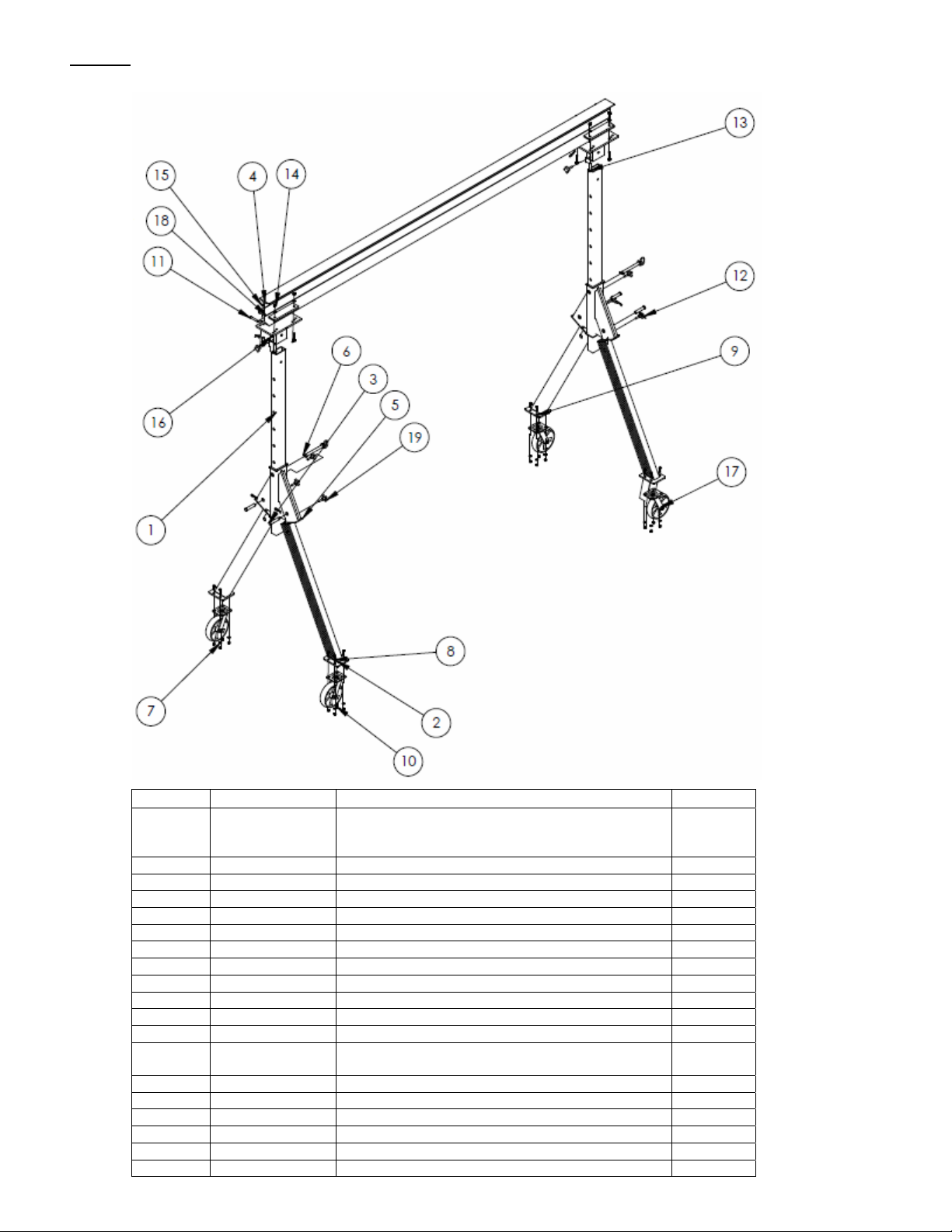
UUUFIG. 2UUU: Adjustable Height Aluminum Gantry Crane models AHA-2-10-8, AHA-2-10-
10,
& AHA-2-10-12
Item no. Part no. Description Quantity
1 33-112-034 ¾ in. x 3 3/4 in. clevis pin 4
28-014-228
2
28-014-191
28-014-192
3 28-014-986-002 6in. I-beam extrusion 1
4 28-014-190 2,000lb.max. rated load aluminum casting 2
5 28-112-007 ¾ in. retaining pin 2
6 33082 3/8 in. zinc-plated SAE flat washer 16
7 11107 3/8 in. – 16 x 1¼ in. HHCS #2 zinc-plated bolt 16
8 33622 3/8 in. zinc-plated lock washer 16
9 36106 3/8 in. – 16 zinc-plated hex nut 16
10 28-112-029 ½ in. x 3in. zinc-plated retaining clevis pin 2
11 33626 ½ in. zinc-plated lock washer 8
12 45286 3/8 in. x 25/8 in. #11 Hitch pin clip 6
13 16-132-249 GFN-8/2-S 4-way swivel lock caster 4
14 28-524-013 Top end cap weldment frame 2
15 28-516-054 I-beam clamp weldment 4
16 08-025-007 Knob 8
17 19213-B ½ in. – 12 x 2½ in. A325 structural nut & bolt combination 8
18 192 13-A ½ in. – 13 A325 structural nut & bolt combination 8
19 28-514-220 Leg weldment 4
AHA-2-10-8 telescoping tube, or
AHA-2-10-10 telescoping tube, or
AHA-2-10-12 telescoping tube
2
Copyright 2011 Vestil Manufacturing Corp. Page 6 of 25
Page 7
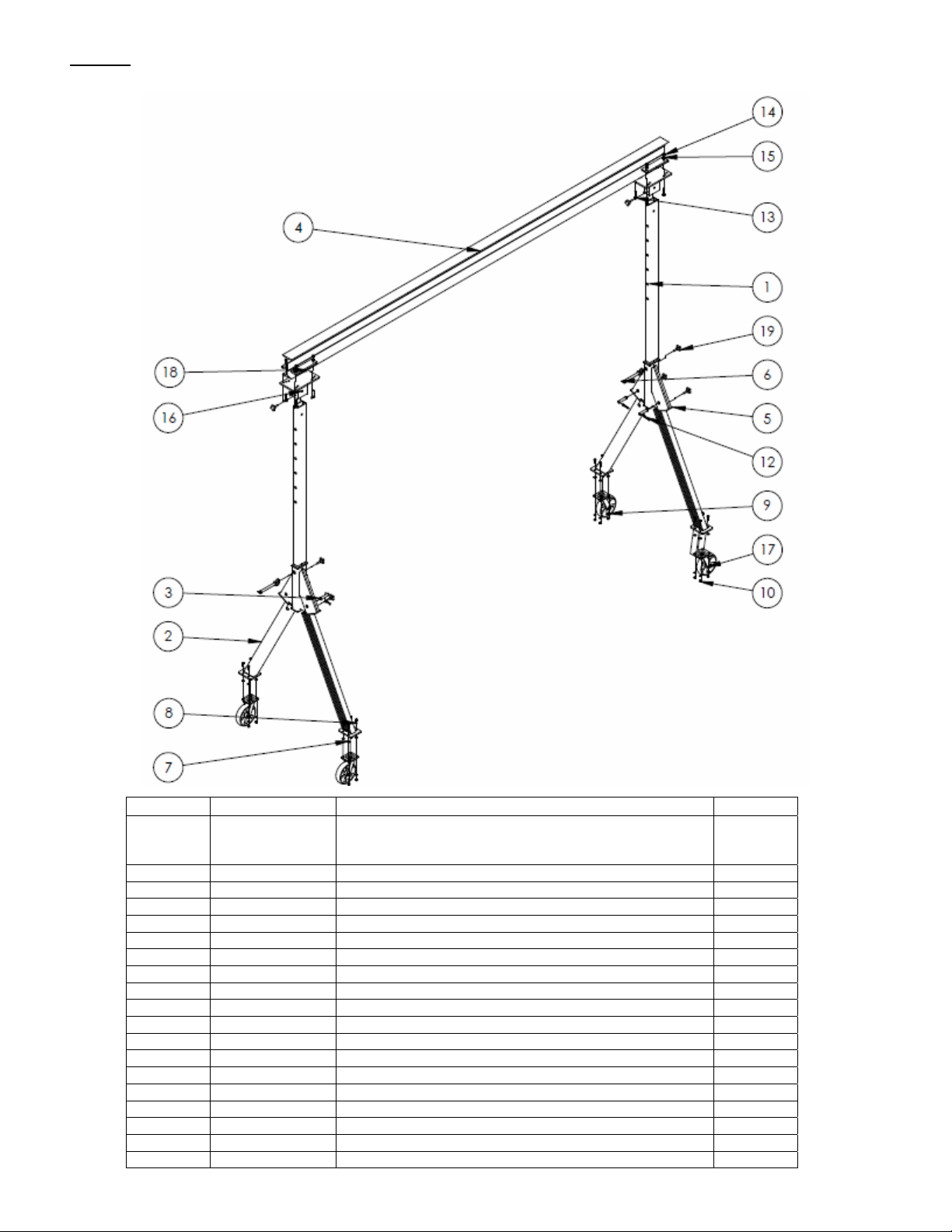
UUUFIG. 3UUU: Adjustable Height Aluminum Gantry Crane models AHA-2-12-8,
AHA-2-12-10, & AHA-2-12-12
Item no. Part no. Description Quantity
28-014-228
1
28-014-191
28-014-192
2 28-514-220 Leg weldment 4
3 33-112-034 ¾ in. x 3 3/4 in. clevis pin 4
4 28-014-987-002 8in. I-beam extrusion 1
5 28-014-190 2,000lb.max. rated load aluminum casting 2
6 28-112-007 ¾ in. retaining pin 2
7 33082 3/8 in. zinc-plated SAE flat washer 16
8 11107 3/8 in. – 16 x 1¼ in. HHCS #2 zinc-plated bolt 16
9 33622 3/8 in. zinc-plated lock washer 16
10 36106 3/8 in. – 16 zinc-plated hex nut 16
11 28-112-029 ½ in. x 3in. zinc-plated retaining clevis pin 2
12 45286 3/8 in. x 25/8 in. #11 Hitch pin clip 6
13 19213-B
14 192 13-A ½ in. – 13 A325 structural nut & bolt combination 8
15 33626 ½ in. zinc-plated lock washer 8
16 28-524-013 Top end cap weldment frame 2
17 16-132-249 GFN-8/2-S 4-way swivel lock caster 4
18 28-516-054 I-beam clamp weldment 4
19 08-025-007 Knob 8
Copyright 2011 Vestil Manufacturing Corp. Page 7 of 25
AHA-2-12-8 telescoping tube
AHA-2-12-10 telescoping tube
AHA-2-12-12 telescoping tube
½ in. – 12 x 2½ in. A325 structural nut & bolt
combination
2
8
Page 8
UUUFIG. 4UUU: Adjustable Height Aluminum Gantry Crane models AHA-2-15-8, AHA-2-15-
10,
& AHA-2-15-12
Item no. Part no. Description Quantity
28-014-228
1
2 28-514-220 Leg weldment 4
3 33-112-034 ¾ in. x 3 3/4 in. clevis pin 4
4 28-014-988-004 8in. I-beam extrusion 1
5 28-014-190 2,000lb. maximum rated load aluminum casting 2
6 28-112-007 ¾ in. retaining pin 2
7 33082 3/8 in. zinc-plated SAE flat washer 16
8 11107 3/8 in. – 16 x 1¼ in. HHCS #2 zinc-plated bolt 16
9 33622 3/8 in. zinc-plated lock washer 16
10 36106 3/8 in. – 16 zinc-plated hex nut 16
11 28-112-029 ½ in. x 3in. zinc-plated retaining clevis pin 2
12 45286 3/8 in. x 25/8 in. #11 Hitch pin clip 6
13 19213-B ½ in. – 12 x 2½ in. A325 structural nut & bolt combination 8
14 19213-A ½ in. – 13 A325 structural nut & bolt combination 8
15 33626 ½ in. zinc-plated lock washer 8
16 28-524-013 Top end cap weldment frame 2
17 16-132-249 GFN-8/2-S 4-way swivel lock caster 4
18 28-516-054 I-beam clamp weldment 4
19 08-025-007 Knob 8
28-014-191
28-014-192
Copyright 2011 Vestil Manufacturing Corp. Page 8 of 25
AHA-2-15-8 telescoping tube frame
AHA-2-15-10 telescoping tube frame
AHA-2-15-12 telescoping tube frame
2
Page 9

UUUFIG. 5UUU: Adjustable Height Aluminum Gantry Crane models AHA-4-8-8, AHA-4-8-10, &
AHA-4-8-12
Item no. Part no. Description Quantity
1 28-014-272 4,000lb. maximum rated load aluminum casting 2
2 28-112-007 ¾ in. retaining pin 2
28-014-229
3
4 28-014-987-001 8 in. I-beam extrusion 1
5 33626 ½ in. zinc-plated lock washer 8
6 28-112-030 ½ in. x 3½ in. zinc-plated retaining clevis pin 2
7 45286 3/8 in. x 25/8 in. #11 Hitch pin clip 6
8 28-112-031 ¾ in. x 4½ in. clevis pin 4
9 33082 3/8 in. zinc-plated SAE flat washer 16
10 11107 3/8 in. – 16 x 1¼ in. HHCS #2 zinc-plated bolt 16
11 33622 3/8 in. zinc-plated lock washer 16
12 36106 3/8 in. – 16 zinc-plated hex nut 16
13 28-524-014 Top cap weldment 2
14 19213-B
15 192 13-A ½ in. – 13 A325 structural nut & bolt combination 8
16 16-132-249 GFN-8/2-S 4-way swivel lock caster 4
17 28-516-054 I-beam clamp weldment 4
18 08-025-007 Knob 8
19 28-514-221 Leg weldment 4
28-014-193
28-014-194
Copyright 2011 Vestil Manufacturing Corp. Page 9 of 25
AHA-4-8-8 telescoping tube
AHA-4-8-10 telescoping tube
AHA-4-8-12 telescoping tube
½ in. – 12 x 2½ in. A325 structural nut & bolt
combination
2
8
Page 10

UUUFIG. 6UUU: Adjustable Height Aluminum Gantry Crane models AHA-4-10-8, AHA-4-10-10,
& AHA-4-10-12
Item no. Part no. Description Quantity
1 28-014-272 4,000lb. maximum rated load aluminum casting 2
2 28-112-007 ¾ in. retaining pin 2
28-014-229
3
28-014-193
28-014-194
4 28-014-988-001 8 in. I-beam extrusion 1
5 33626 ½ in. zinc-plated lock washer 8
6 28-112-030 ½ in. x 3½ in. zinc-plated retaining clevis pin 2
7 45286 3/8 in. x 25/8 in. #11 Hitch pin clip 6
8 28-112-031 ¾ in. x 4½ in. clevis pin 4
9 33082 3/8 in. zinc-plated SAE flat washer 16
10 11107 3/8 in. – 16 x 1¼ in. HHCS #2 zinc-plated bolt 16
11 33622 3/8 in. zinc-plated lock washer 16
12 36106 3/8 in. – 16 zinc-plated hex nut 16
13 28-524-014 Top cap weldment 2
14 19213-B
15 192 13-A ½ in. – 13 A325 structural nut & bolt combination 8
16 16-132-249 GFN-8/2-S 4-way swivel lock caster 4
17 28-516-054 I-beam clamp weldment 4
18 08-025-007 Knob 8
19 28-514-221 Leg weldment 4
Copyright 2011 Vestil Manufacturing Corp. Page 10 of 25
AHA-4-10-8 telescoping tube
AHA-4-10-10 telescoping tube
AHA-4-10-12 telescoping tube
½ in. – 12 x 2½ in. A325 structural nut & bolt
combination
2
8
Page 11

UUUFIG. 7UUU: Adjustable Height Aluminum Gantry Crane models AHA-4-12-8, AHA-4-12-10,
& AHA-4-12-12
Item no. Part no. Description Quantity
1 28-014-272 4,000lb. maximum rated load aluminum casting 2
2 28-112-007 ¾ in. retaining pin 2
28-014-229
3
28-014-193
28-014-194
4 28-014-988-002 8 in. I-beam extrusion 1
5 33626 ½ in. zinc-plated lock washer 8
6 28-112-030 ½ in. x 3½ in. zinc-plated retaining clevis pin 2
7 45286 3/8 in. x 25/8 in. #11 Hitch pin clip 6
8 28-112-031 ¾ in. x 4½ in. clevis pin 4
9 33082 3/8 in. zinc-plated SAE flat washer 16
10 11107 3/8 in. – 16 x 1¼ in. HHCS #2 zinc-plated bolt 16
11 33622 3/8 in. zinc-plated lock washer 16
12 36106 3/8 in. – 16 zinc-plated hex nut 16
13 28-524-014 Top cap weldment 2
14 19213-B
15 192 13-A ½ in. – 13 A325 structural nut & bolt combination 8
16 16-132-249 GFN-8/2-S 4-way swivel lock caster 4
17 28-516-054 I-beam clamp weldment 4
18 08-025-007 Knob 8
19 28-514-221 Leg weldment 4
Copyright 2011 Vestil Manufacturing Corp. Page 11 of 25
AHA-4-12-8 telescoping tube
AHA-4-12-10 telescoping tube
AHA-4-12-12 telescoping tube
½ in. – 12 x 2½ in. A325 structural nut & bolt
combination
2
8
Page 12

UUUFIG. 8UUU: Adjustable Height Aluminum Gantry Crane models AHA-4-15-8, AHA-4-15-10, & AHA-4-
15-12
Item no. Part no. Description Quantity
1 28-014-272 4,000lb. maximum rated load aluminum casting 2
2 28-112-007 ¾ in. retaining pin 2
28-014-229
3
28-014-193
28-014-194
4 33626 ½ in. zinc-plated lock washer 8
5 28-112-030 ½ in. x 3½ in. zinc-plated retaining clevis pin 2
6 45286 3/8 in. x 25/8 in. #11 Hitch pin clip 6
7 28-112-031 ¾ in. x 4½ in. clevis pin 4
8 33082 3/8 in. zinc-plated SAE flat washer 16
9 11107 3/8 in. – 16 x 1¼ in. HHCS #2 zinc-plated bolt 16
10 33622 3/8 in. zinc-plated lock washer 16
11 36106 3/8 in. – 16 zinc-plated hex nut 16
12 28-524-014 Top cap weldment 2
13 19213-B
14 192 13-A ½ in. – 13 A325 structural nut & bolt combination 8
15 16-132-249 GFN-8/2-S 4-way swivel lock caster 4
16 28-014-236 10 in. H aluminum I-beam extrusion 1
17 28-516-054 I-beam clamp weldment 4
18 08-025-007 Knob 8
19 28-514-221 Leg weldment 4
Copyright 2011 Vestil Manufacturing Corp. Page 12 of 25
AHA-4-15-8 telescoping tube
AHA-4-15-10 telescoping tube
AHA-4-15-12 telescoping tube
½ in. – 12 x 2½ in. A325 structural nut & bolt
combination
2
8
Page 13

UUUFIG. 9UUU: Adjustable Height Aluminum Gantry Crane models AHA-6-8-8, AHA-6-8-10, &
AHA-6-8-12
Item no. Part no. Description Quantity
28-014-299
1
28-014-300
28-014-301
2 28-514-189 Leg set weldment 2
3 16-132-064 PH-8/3-RB-4-Way swivel lock caster 4
4 11209 ½ in. – 13 x 1½ in. HHCS #2 zinc-plated bolt 16
5 28-112-007 ¾ in. retaining pin 2
6 28-112-036 ½ in. zinc-plated clevis pin 2
7 45286 1/8 in. – 16 x in. 25/8 in. #11 hitch pin 2
8 33626 ½ in. zinc-plated lock washer 8
9 37030 ½ in. – 13 nylon insert lock nu t 16
10 28-524-015 Top cap weldment 2
11 19213-B
12 192 13-A ½ in. -13 A325 structural nut & bolt combination 8
13 28-014-355 10 in. H aluminum I-beam extrusion 1
14 28-516-054 I-beam clamp weldment 4
15 08-025-007 Knob 2
Copyright 2011 Vestil Manufacturing Corp. Page 13 of 25
AHA-6-8-8 telescoping tube
AHA-6-8-10 telescoping tube
AHA-6-8-12 telescoping tube
½ in. -13 x 2½ in. A325 structural nut & bolt
combination
2
8
Page 14

UUUFIG. 10UUU: Adjustable Height Aluminum Gantry Crane models AHA-6-10-8, AHA-6-10-10,
& AHA-6-10-12
Item no. Part no. Description Quantity
1 28-514-189 Leg set weldment 2
2 16-132-064 PH-8/3-RB-4-Way swivel lock caster 4
3 11209 ½ in. – 13 x 1½ in. HHCS #2 zinc-plated bolt 16
4 28-112-007 ¾ in. retaining pin 2
5 28-112-036 ½ in. zinc-plated clevis pin 2
6 45286 1/8 in. – 16 x in. 25/8 in. #11 hitch pin 2
7 33626 ½ in. zinc-plated lock washer 8
28-014-299
8
28-014-300
28-014-301
9 37030 ½ in. – 13 nylon insert lock nu t 16
10 28-524-015 Top cap weldment 2
11 19213-B
12 192 13-A ½ in. -13 A325 structural nut & bolt combination 8
13 28-014-356 10 in. H aluminum I-beam extrusion 1
14 28-516-054 I-beam clamp weldment 4
15 08-025-007 Knob 2
Copyright 2011 Vestil Manufacturing Corp. Page 14 of 25
AHA-6-10-8 telescoping tube
AHA-6-10-10 telescoping tube
AHA-6-10-12 telescoping tube
½ in. -13 x 2½ in. A325 structural nut & bolt
combination
2
8
Page 15

UUUFIG. 11UUU: Adjustable Height Aluminum Gantry Crane models AHA-6-12-8, AHA-6-12-10,
& AHA-6-12-12
Item no. Part no. Description Quantity
1 28-514-189 Leg set weldment 2
2 16-132-064 PH-8/3-RB-4-Way swivel lock caster 4
3 11209 ½ in. – 13 x 1½ in. HHCS #2 zinc-plated bolt 16
4 28-112-007 ¾ in. retaining pin 2
5 28-112-036 ½ in. zinc-plated clevis pin 2
6 45286 1/8 in. – 16 x in. 25/8 in. #11 hitch pin 2
7 33626 ½ in. zinc-plated lock washer 8
28-014-299
8
28-014-300
28-014-301
9 37030 ½ in. – 13 nylon insert lock nu t 16
10 28-014-358 12 in. H aluminum I-beam extrusion 1
11 28-524-015 Top cap weldment 2
12 19213-B
13 192 13-A ½ in. -13 A325 structural nut & bolt combination 8
14 28-516-061 I-beam clamp weldment 4
15 08-025-007 Knob 2
AHA-6-12-8 telescoping tube
AHA-6-12-10 telescoping tube
AHA-6-12-12 telescoping tube
½ in. -13 x 2½ in. A325 structural nut & bolt
combination
2
8
Copyright 2011 Vestil Manufacturing Corp. Page 15 of 25
Page 16

UUUFIG. 12UUU: Adjustable Height Aluminum Gantry Crane models AHA-6-15-8, AHA-6-15-10,
& AHA-6-15-12
10
Item no. Part no. Description Quantity
1 28-514-189 Leg set weldment 2
2 16-132-064 PH-8/3-RB-4-Way swivel lock caster 4
3 11209 ½ in. – 13 x 1½ in. HHCS #2 zinc-plated bolt 16
4 28-112-007 ¾ in. retaining pin 2
5 28-112-036 ½ in. zinc-plated clevis pin 2
6 45286 1/8 in. – 16 x in. 25/8 in. #11 hitch pin 2
7 33626 ½ in. zinc-plated lock washer 8
28-014-299
8
9 37030 ½ in. – 13 nylon insert lock nu t 16
10 28-014-358 12 in. H aluminum I-beam extrusion 1
11 28-524-015 Top cap weldment 2
12 19213-B
13 192 13-A ½ in. -13 A325 structural nut & bolt combination 8
14 28-516-061 I-beam clamp weldment 4
15 08-025-007 Knob 2
28-014-300
28-014-301
AHA-6-15-8 telescoping tube
AHA-6-15-10 telescoping tube
AHA-6-15-12 telescoping tube
½ in. -13 x 2½ in. A325 structural nut & bolt
combination
2
8
Copyright 2011 Vestil Manufacturing Corp. Page 16 of 25
Page 17

ASSEMBLY INSTRUCTIONS:
If the crane is improperly assembled, it might malfunction and result in serious personal injuries.
Read this instruction manual in its entirety before assembling the crane; only assemble the crane if you fully
understand both the associated risks and the manufacturer-approved assembly procedure discussed below.
Failure to apply the assembly procedure described in Steps 1-8 below constitutes misuse of the product.
ONLY qualified personnel should assemble the crane.
DO NOT modify the crane in any way UUUunless and untilUUU you receive written approval from Vestil.
DO NOT use the crane if you notice damage to or deformation of the beam, teletubes, or any component of either
of the leg assemblies. Using the crane despite weakness of a structural component could result in crane collapse.
DO NOT use the crane if any of the hardware (bolts, nuts, clamps, etc.) is damaged; you could sustain serious
injuries if the crane collapses. Contact Vestil to order replacement parts.
DO NOT use the crane if any of the casters is damaged. A damaged caster may cause the crane to tip over, and
the possibility that the crane will tip increases while it is used to hoist or support a load.
Modifying the crane in any way automatically voids the limited warranty.
This crane can be used outdoors. However, it should be sheltered from the weather when not in use.
Inspect the crane for damage before each use.
UUUStep 1UUU: [2,000 lb. AHA-2-#-# and 4,000 lb. AHA-4-#-# models only] Attach the leg weldments and yokes
Insert the end of each leg weldment into one of the leg openings of the yoke (circled) as shown below. Fasten the leg
weldments to the yoke with clevis pins (AHA-2 models part no. 28-112-031; AHA-4 models part no. 33-112-034), and then
secure the clevis pins by feeding a hitch pin through the hitch pin opening (in the clevis pin). Stabilize the leg weldments in
the yoke by winding a knob through yoke until the end of the knob presses firmly against the leg.
Diagram 1: Attach leg weldments to yoke
¾ in. diameter clevis pin
(28-112-031 or 33-112-034)
Hitch pin
opening
Caster mount bracket
Yoke
3
/8 in. - 16 x 1¼ in. knob
Leg weldment
Hitch pin
Copyright 2011 Vestil Manufacturing Corp. Page 17 of 25
Page 18

Step 2: Fasten teletubes to leg assemblies (AHA-6-#-# series; 6,000 lb. capacity models) or yokes (2,000 lb. and 4,000
lb. models).
UUUNOTE: If you ordered a “Come-along” kit, perform Step 8 on p. 21 first.
Insert the teletubes through the sleeves of the leg assemblies or yokes. Align the 3rd pinhole in each teletube with the
pinhole in the leg assemblies or yoke as is depicted in Diagram 2A below.
Pin each teletube to a leg assembly through the same (3rd) pinhole with adjustment pins (see Diagram 2A below as well
as the exploded parts diagrams on p. 5-16).
Diagram 2A: Teletube-to-Leg Assembly
Connections
Caster mount bracket
Adjustment pin (part no. 28-112-007)
Pin teletube
to leg
assembly
Yoke
Leg weldment
Diagram 2B: Top Cap-to-Teletube Connection
Hitch pin
½ in. -13 x 2½ in.
A325 structural
bolt
Welded beam clamp
A325 Nut
½in. zincplated lock
washer
½in. x 3in. zincplated clevis pin
Top cap
Step 3: Attach 1 welded beam clamp to each top cap
Diagram 3A
Measure width of I-beam
flange (double arrow)
½ of
flange
width
Beam
bracket
Diagram 3B
Teletube
Knob
Centerline of beam bracket
Centerline of
beam bracket
Hitch pin
Dashed area
represents width of
beam flange
Centerline of beam flange
Measure the flange width of the I-beam. Find the center of the
beam bracket and measure half the width of the flange on either
side of the centerline.
Identify the 4 bolt holes in the beam bracket that lie just outside the
width of the beam flange. Feed A325 structural bolts through those
4 bolt holes of a welded beam clamp as shown at right.
Welded
beam
clamp
Slide a lock washer onto each bolt, and then secure the bolts with
A325 structural nuts. Do not fully tighten the nuts at this point.
Copyright 2011 Vestil Manufacturing Corp. Page 18 of 25
A325
structural
nut
½ in. zinc-plated lock washer
A325 structural bolt
Page 19

Step 4: Fasten the teletubes to the I-beam.
Insert the flange of the I-beam into the gap between the beam clamp and the beam bracket (see dotted oval and arrow in
Diagram 4B below); then secure the flange on the opposite side to the beam bracket by installing another beam clamp as
shown in Diagram 4A.
Diagram 4A: End View of I-beam Connection to Beam Bracket
Diagram. 4B: Clamp the I-beam to the tops of the teletubes
Top cap
I-beam
1
Welded beam clamp
Teletube
3
of Teletube
2
3
Diagram 4C: Exploded Parts View of Beam Clamp Connection to Top Cap
I-beam
3
4
Welded
beam
bracket
1
2
Beam
bracket
Teletube
Diagram 4D: Top view of beam connection to teletube
Lower beam flange
*Item no. Part no. Description Quantity
1 33626 ½ in. lock washer 8
2 19213-A ½ in. – 13 structural nut 8
3 19213-B ½ in. – 13 x 2½ in. bolt 8
4 28-516-053 Welded beam clamp 4
Copyright 2011 Vestil Manufacturing Corp. Page 19 of 25
Page 20

Step 5: Tighten the beam clamp fasteners. Make sure that the I-beam is centered on the beam brackets and that the be am
3
(AHA
)
p
)
clamps significantly overlap the beam flange on both sides.
Step 6
: Stand the crane on its feet.
Rotate the crane onto its feet in a controlled manner. [For instance, attach a hoist chain to the I-beam and then slowly
raise the beam until the crane rotates to stand on its feet. Alternatively, raise the crane with a fork truck: Position the forks
under the I-beam and slowly raise the beam until the crane rotates onto its feet in a controlled manner.]
Approach the crane with a
fork truck from this side, and
Diagram 6: Rotate crane onto its feet
slide the forks under the Ibeam.
Slowly raise the beam and
slowly drive forward until the
crane stands on its feet.
DO NOT raise
the beam unless all other
persons have moved to a
location away from and
behind the fork truck.
Step 7
: Connect the casters to the legs (Diagrams 5A & 5B show standard casters).
Attach each caster to the caster mount bracket of each leg using the hardware shown in Diagrams 5A & 5B. Raise the
crane 8 to 10 inches off of the ground with a fork lift or hoist. Position a caster underneath each foot as shown in the
diagram below and fasten it to the caster mount bracket.
/8 in. -16 x 1¼ in. HHCS
#2 zinc-plated bolt
½ in. – 13 nylon
insert lock nut
3
/8 in. SAE zinc-plated
3
flat washer
3
hex
nut
½ in. -13 x 1½ in.
HHCS #2 zinc-
plated bolt
3
/8 in. zinc-plated
lock washer
3
/8 in. zinc-plated
Slide a lock washer followed by a flat washer onto a 1¼ in. bolt, and
feed the bolt up through the bolt holes in the caster and caster mount
bracket. Put a lock washer onto the bolt and fasten a nut to the end of
the bolt.
Diagram 7A: Caster installation for 2,000 pound and 4,000
ound capacity models (AHA-2-#-# and AHA-4-#-#
Diagram 7B: Caster installation for 6,000 lb. capacity
models
-6-#-#
Copyright 2011 Vestil Manufacturing Corp. Page 20 of 25
Page 21

Step 8: If you have a “Come-Along” kit used to manually adjust the height of the crane, install the cable loops before
inserting the teletubes.
Twist the cable loop into an “8” and fold the top of
the 8 over onto the bottom part of the 8 (this will
double loop the cable). Then slide the doubled
loop onto the yoke.
Use Instructions
NOTE: Before using the crane for the first time, perform the “Initial Inspection” described on p. 22.
Crane operators are responsible for operating the crane in a safe manner. To reduce the likelihood of
serious personal injuries or death resulting as a consequence of negligent operation:
Only use this crane if you are qualified and trained to use it. The operating instructions in this manual supplement
safe crane and hoist operation practices learned during your training program.
ALWAYS apply the safe material handling practices learned from your training program.
All personnel not participating in the use of the crane must stay out of the area during use. Be certain no part of any
person or object is under any part of the boom (I-beam) or the suspended load at any time and particularly before
lowering it. Instruct all persons to remain at a safe distance during operation.
Always carefully watch the boom and any load hanging from it while using the crane.
Always follow the hoist and trolley manufacturers’ instructions regarding proper use of their products.
BEFORE the load is connected to the hoist, lock or immobilize the casters (for instance with chocks).
DO NOT use the crane and notify your supervisor and authorized maintenance personnel if: 1) you observe any
damage or hear unusual noise during operation; or 2) you observe any warping or deformation of the beam, the
teletubes, the load hook or chain/cable.
Proper loading:
Position the trolley and hoist directly above
the load. Center the trolley and hoist above
the center of the load and position the long
axis of the I-beam above the center of the
load. Proper positioning is diagrammed in Fig.
6.
Connect the load to the hoist chain/cable,
according to the instructions supplied with
your hoist and the method applied at your
work site; then raise the load only
as high as is
necessary to position it. Once the load is
properly centered above the work location,
lower the load until it is fully supported by the
ground or work surface and disconnect the
load from the hoist. Return the crane to its
storage locations.
If you must move the load to a different
location, return the load to the ground or other
supporting surface, e.g. pallet, and disconnect
it from the hoist. Move the crane and load
separately to the desired work location.
Only use the crane to lift loads
.
Diagram 8A: Center the trolley
above the center of the load
Diagram 8B: Center the long
axis of the I-beam above the
center of the load.
Copyright 2011 Vestil Manufacturing Corp. Page 21 of 25
Page 22

Festoon Kit (option)
Copyright 2011 Vestil Manufacturing Corp. Page 22 of 25
Page 23

Inspections and Maintenance
Owner(s)/end-user(s) of the crane should apply Occupational Safety and Health Administration (OSHA) crane
inspection procedures (see 29 CFR 1910.179 by visiting http://www.osha.gov/ and navigate to “Regulations”; then to
“General Industry” standards, section 1910.179. However, the end-user should realize that occupational safety and
health laws and regulations of the state where the crane is used, rather than federal OSHA regulations, are controlling
authority). Inspections are classified according to the intervals at which inspection should be performed. The identity
of the components to be inspected and the degree to which those components wear, deteriorate, or malfunction
determine how frequently you must inspect the crane. 29 CFR 1910.179(j) describes the various inspections the end
user is responsible for performing on this crane:
1. Initial inspection — before a new or modified crane may be used for the first time, it must be inspected
to insure normal condition. Conduct a “Frequent inspection” as described next.
After the first use, the crane end-user/owner must conduct the follo wing 2 types of inspection :
2. Frequent inspection
[29 CFR 1910.179(j)(1)(ii)(a)] — Daily to monthly intervals.
The following items shall be inspected for defects at the intervals specifically indicated, including
observation during operation for any defects which might appear between inspections. All deficiencies
such as those listed shall be carefully examined to determine whether they constitute a safety hazard:
[Inspect daily] All functional operating mechanisms (wheels/casters, teletubes, leg tubes, pins,
and yokes) for maladjustment interfering with proper operation. Verify that the wheels/casters
roll smoothly by pushing/pulling the crane 4-6 feet in one direction.
[Inspect daily] Look for deterioration or leakage in lines, tanks, valves, drain pumps, and other
parts of air or hydraulic systems. [not applicable]
[Inspect daily (visually); inspect monthly and make a certification record, which includes
the date of inspection, the signature of the person who performed the inspection and the
serial number (or other identifier) of the hook inspected] Hooks with deformation or cracks.
Immediately discard hooks with cracks or that have a throat opening that is more than 15
percent in excess of normal throat opening, or that are twisted more than 10° from the plane of
the unbent hook.
[Inspect daily (visually); monthly inspection with a certification record which includes
the date of inspection, the signature of the person who performed the inspection and an
identifier of the chain which was inspected] Hoist chains, including end connections, for
excessive wear, twist, distorted links interfering with proper function, or stretch beyond hoist
manufacturer's recommendations.
[Inspect weekly] All functional operating mechanisms (wheels/casters, teletubes, leg tubes,
pins, and yokes, bolts and nuts, including anchor bolts and nuts) for excessive wear.
[Inspect weekly] Rope reeving for noncomplian ce with hoist manufacturer's recommendations.
3. Periodic inspection [29 CFR 1910.179(j)(1)(ii)(b)] — 1 to 12-month intervals.
Complete inspections of the crane shall be performed at intervals depending upon its activity, severity
of service, and environment, or as specifically indicated below. Perform all of the requirements
described for frequent inspections and the following bulleted items. Carefully examine the crane for any
problems such as those listed below to determine whether they constitute a safety hazard:
Deformed, cracked, or corroded members.
Loose bolts or rivets.
Cracked or worn sheaves and drums.
Worn, cracked or distorted parts such as pins, bearings, shafts, gears, rollers, locking and
clamping devices.
Excessive wear on brake system parts, linings, pawls, and ratchets.
Load, wind, and other indicators over their full range, for any significant inaccuracies.
Gasoline, diesel, electric, or other power plants for improper performance or noncompliance
with applicable safety requirements.
Excessive wear of chain drive sprockets and excessive chain stretch.
Electrical apparatus, for signs of pitting or any deterioration of controller contactors, limit
switches and pushbutton stations.
Cranes not in regular use: for each of the 3 bullet points below, in addition to the crane inspection all
rope which has been idle for a period of a month or more due to shutdown or storage of a crane on
which it is installed must be given a thorough inspection before it is used. An appointed person, whose
approval is required before the rope may be used, must inspect the rope for all types of deterioration. A
certification record must be available for inspection. The record must include at least the date of
inspection, the signature of the person who performed the inspection and an identifier for the rope
inspected.
Copyright 2011 Vestil Manufacturing Corp. Page 23 of 25
Page 24

A crane which has been idle for a period of 1 month or more, but less than 6 months, shall
undergo a “Frequent inspection” before being returned to service.
A crane which has been idle for a period of over 6 months shall be given a “Complete
inspection” before placing in service.
Standby cranes shall be given a “Frequent inspection” at least semi-annually (twice per year;
1 inspection each 6 months).
Product Markings and Labels
NOTE: Periodically inspect the labels affixed to the product. Clean the labels as necessary to maintain legibility
from a reasonable, safe viewing distance as recommended in ANSI Z535.4 (section 10.21). Contact the
manufacturer for replacement labels.
Label #599 #397 #398
(Both Sides of I-Beam) Label #391
Label #256
Label #287
Copyright 2011 Vestil Manufacturing Corp. Page 24 of 25
Page 25

LIMITED WARRANTY
Vestil Manufacturing Corporation (“Vestil”) warrants this product to be free of defects in material and workmanship
during the warranty period. Our warranty obligation is to provide a replacement for a defective original part if the part
is covered by the warranty
, after we receive a proper request from the warrantee (you) for warranty service.
Who may request service?
Only a warrantee may request service. You are a warrantee if you purchased the product from Vestil or from an
authorized distributor AND Vestil has been fully paid.
What is an “original part”?
An original part is a part used to make the product as shipped
to the warrantee.
What is a “proper request”?
A request for warranty service is prop er if Vestil receives: 1) a photocopy of the Customer Invoice
that displays the
shipping date; AND 2) a written request for warranty service including your name and phone number. Send requests
by any of the following methods:
Mail Fax Email
Vestil Manufacturing Corporation (260) 665-1339 sales@vestil.com
2999 North Wayne Street, PO Box 507 Phone
Angola, IN 46703 (260) 665-7586
In the written request, list the parts believed to be defective and include the address where replacements should be
delivered.
What is covered under the warranty?
After Vestil receives your request for warranty service, an authorized representative will contact you to determine
whether your claim is covered by the warranty. Before providing warranty service, Vestil may require you to send the
entire product, or just the defective part or parts, to its facility in Angola, IN. The warranty covers defects in the
following original
also covers defects in original
hoses, wheels, seals, brushes, and batteries.
dynamic components: motors, hydraulic pumps, electronic controllers, switches and cylinders. It
parts that wear under normal usage conditions (“wearing parts”), such as bearings,
How long is the warranty period?
The warranty period for original components is 90 days
. The warranty period begins on the date when Vestil ships the
product to the warrantee. If the product was purchased from an authorized distributor, the period begins when the
distributor ships the product. Vestil may extend the warranty period for products shipped from authorized distributors
by up to 30 days to account for shipping time.
If a defective part is covered by the warranty, what will Vestil do to correct the problem?
Vestil will provide an appropriate replacement for any covered part. An authorized representative of Vestil will contact
you to discuss your claim.
What is not covered by the warranty?
1. Labor;
2. Freight;
3. Occurrence of any of the following automatically voids the warranty
:
Product misuse;
Negligent operation or repair;
Corrosion or use in corrosive conditio ns;
Inadequate or improper maintenance;
Damage sustained during shipping;
Accidents involving the product;
Unauthorized modifications
: DO NOT modify the product IN ANY WAY without first receiving
written authorization from Vestil. Modification(s) might make the product unsafe to use or might
cause excessive and/or abnormal wear.
Do any other warranties apply to the product?
Vestil Manufacturing Corp. makes no other express warranties. All implied warranties are disclaimed to the extent
allowed by law. Any implied warranty not disclaimed is limited in scope to the terms of this Limited Warranty.
Copyright 2011 Vestil Manufacturing Corp. Page 25 of 25
 Loading...