

Page 1
rev. 12/14/2012 ABLT-H, Manual
y
VESTIL MANUFACTURING CORP.
2999 North Wayne Street, P.O. Box 507, Angola, IN 46703
Telephone: (260) 665-7586 -or- Toll Free (800) 348-0868
Fax: (260) 665-1339
www.vestilmfg.com e-mail: sales@vestil.com
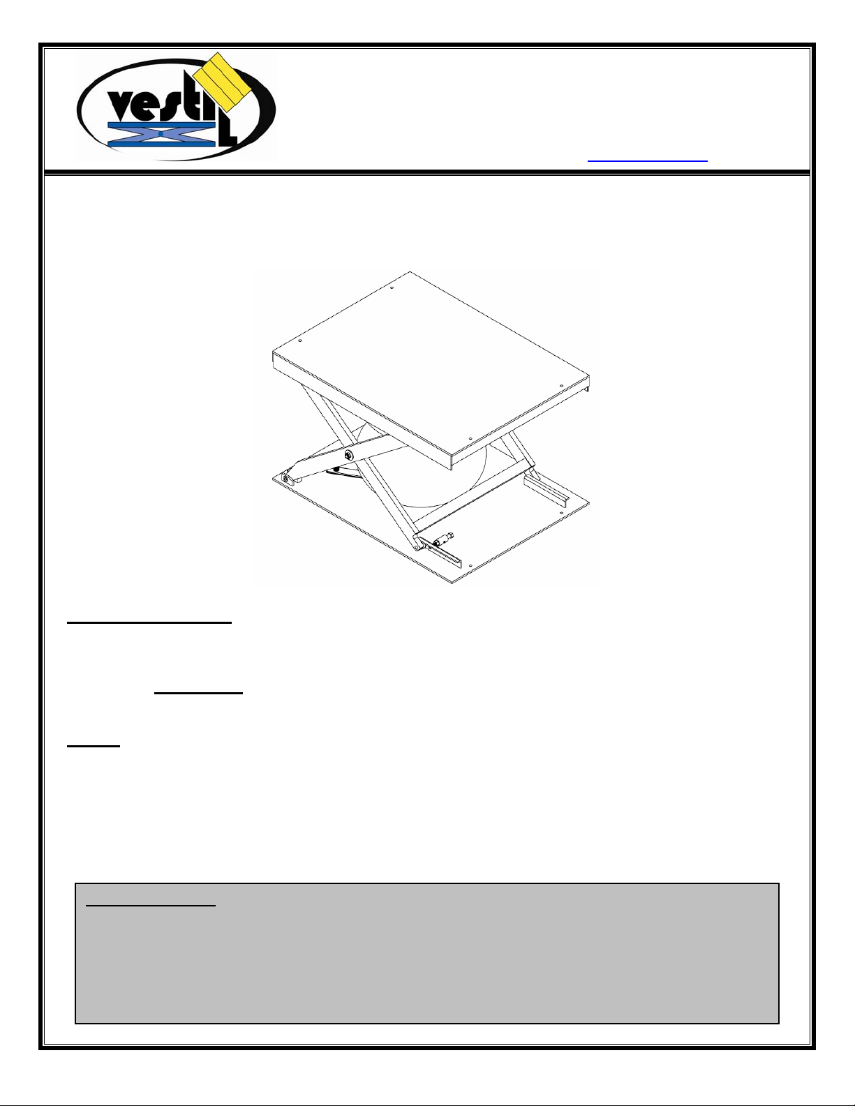
ABLT-H-LP SERIES AIR BAG LIFT TABLES
INSTRUCTION MANUAL
Receiving instructions:
After delivery, IMMEDIATELY remove the packaging from the Hook-Base in a manner that preserves the
packaging and maintains the orientation of the product in the packaging; then inspect the product closely
to determine whether it sustained damage during transport. If damage is discovered during the
inspection, immediately
record a complete description of the damage on the bill of lading. If the
product is undamaged, discard the packaging.
NOTES
:
1) Compliance with laws, regulations, codes, and non-voluntary standards enforced in the location where
the product is used is exclusively the responsibility of the owner/end-user.
2) VESTIL is not liable for any injury or property damage that occurs as a consequence of failing to apply either:
a) the instructions in this manual; or b) information provided on labels affixed to the product. Neither is Vestil
responsible for any consequential damages sustained as a result of failing to exercise sound judgment
while assembling, installing, using or maintaining this product.
Table of Contents
Hazard identification: explanation of signal words…………………………………………………………………… 2
Safety Guidelines………………………………………………………………………………………… …………….. 2
Product specifications by model……………………..………………………………………………………………… 3
Installation………………………………………………………………………………………………………………... 3
Operation………………………………………………………………………………………………………………… 3
Maintenance………………………………………………………………………………........................................3-4
Limited warrant
………………………………………………………………………………………………………….5
Page 1 of 5
Page 2
rev. 12/14/2012 ABLT-H, Manual
Hazard Identification--Explanation of SIGNAL WORDS
This manual uses SIGNAL WORDS to indicate the likelihood of personal injuries, as well as the probable
seriousness of those injuries, if the product is misused in the ways described. Other signal words call attention to
uses of the product likely cause property damage.
The signal words used appear below along with the meaning of each word:
Identifies a hazardous situation which, if not avoided, WILL result in DEATH or
SERIOUS INJURY. Use of this signal word is limited to the most extreme
Identifies a hazardous situation which, if not avoided, COULD result in DEATH or
Indicates a hazardous situation which, if not avoided, COULD result in MINOR or
Identifies practices likely to result in product/property damage, such as operation that
Each person who assembles, installs, uses, or maintains this product should read the entire manual in advance
and fully understand the directions. If after reading the manual you do not understand an instruction, ask
your supervisor or employer for clarification, because failure to adhere to the directions in this manual
might result in serious personal injury.
SAFETY GUIDELINES
Vestil diligently strives to identify foreseeable hazards associated with the use of its products. However, material
handling is inherently dangerous and no manual can address every conceivable risk. The end-user ultimately is
responsible for exercising sound judgment at all times.
situations.
SERIOUS INJURY.
MODERATE injury.
might damage the product.
Electrocution might result if any part of the lift table or work piece placed on the table contacts electrified
wires. Reduce the likelihood of electrocution by applying common sense:
DO NOT contact ele ctrified wires with any part of the table or the load/work piece on it;
Install the table in a location where contact with electrified wires will not occur.
If this product is used improperly or carelessly, the operator and/or bystanders might sustain serious
personal injuries or even be killed. ALWAYS use the product properly:
Failure to read and understand the entire manual before assembling, installing, using or servicing the
product constitutes misuse. Read the manual to refresh your understanding of proper use and maintenance
procedures.
DO NOT exceed the maximum rated load.
Inspect the lift table before each use. DO NOT use this device if the inspection reveals structural damage. Examples
of structural damage include: 1) broken, missing, or deformed legs; 2) damaged, deformed or ruptured air bladder; 3)
cracked welds; 4) enlarged openings for fasteners at pivot points; 5) corrosion, severe wear, or other condition that
affects the ability of the product to support applied weight or itself; 6) damaged, deformed or cracked roller channels.
Immediately lock out a tag out the lift table and replace each part that fails to pass an inspection. DO NOT use the
product until it is fully restored to normal condition. ONLY use manufacturer-approved replacement parts.
DO NOT use the product if any unusual noise or movement is observed. If a malfunction occurs, remove the unit
from service and notify your supervisor or maintenance personnel about the issue.
DO NOT bypass or attempt to bypass the safety lock system.
DO NOT tamper with the pressure relief valve system.
DO NOT use the lift table UNLESS it is securely anchored to the ground.
ALWAYS evenly distribute and center the load on the table.
DO NOT remove or obscure any label. All product labels must be readable and undamaged.
DO NOT use the table to lift or support people.
DO NOT modify the table in any way UNLESS you first obtain written approval from Vestil. Unauthorized
modifications automatically void the limited warranty (see p. 5) and might make the table unsafe to use.
DO NOT use the table UNLESS all product labels are readable and undamaged.
Proper use, maintenance, and storage are essential for this product to function properly.
o Always use this product in accordance with the instructions in this manual and consistent with any training relevant
to scissor lift tables.
o Keep the lift table clean & dry.
Page 2 of 5
Page 3

rev. 12/14/2012 ABLT-H, Manual
p
Product Specifications by Model:
Model
ABLT-H-LP-1-29
ABLT-H-LP-2-29
ABLT-H-LP-3-29
ABLT-H-LP-4-29
ABLT-H-LP-6-23
Capacity in
pounds (kg)
1,000
(~455kg)
2,000
(~909kg)
3,000
(~1,364kg)
4,000
(`1,818kg)
6,000
(`2,727kg)
NOTE: Air supply pressure should be at least 60psi and no more than 120psi.
Installation
1. Install the lift table on a level, even surface. Anchor the table to the floor with appropriatelymatched anchor bolts. Measure the diameter of the bolt holes in the base of the frame, and
install bolts that are at least 4in. long to anchor the table to the floor.
2. Shim the table to level it if necessary.
NOTE: Grout should be placed under the table base to resist warping and bending
forces applied to the base between shims. Grout around the entire perimeter
of the base frame.
3. Connect main air supply to the control pedestal. If no control pedestal is supplied, see
schematic for air inlet.
NOTE: Use only clean, dry air. Use of a filter/regulator is recommended.
Lift Table Operation
1. To raise the table.
a. Press the lever on the control pedestal to the “UP” position.
b. Release the lever as soon as the table reaches the desired height.
2. To lower the lift.
a. Press the lever on the control pedestal to the “DOWN” position.
Maintenance:
Install the maintenance stop before inspecting or maintaining the table. Maintenance stop
installation is explained in FIG. 3 below. [NOTE: When performing maintenance beyond merely
applying lubrication to outer surfaces, use overhead rigging to secure the tabletop.]
FIG. 3: Maintenance prop installation
1) Unload the table; then fully raise the table.
2) Loosen the set screw using a
3) Press the safety stop bolt through the roller guide; then
retighten the set screw.
4) Lower the table until the roller
rests against the safety stop
bolt.
3
/32in. Allen wrench.
Lowered height
in Inches (cm)
1
4
/8in.
(~10.5cm)
1
/8in.
4
(~10.5cm)
1
4
/8in.
(~10.5cm)
1
4
/8in.
(~10.5cm)
1
4
/8in.
(~10.5cm)
Raised height
in Inches (cm)
29in.
(~73.7cm)
29in.
(~73.7cm)
29in.
(~73.7cm)
29in.
(~73.7cm)
23in.
(~58.4cm)
FIG. 4: LOCKOUT attachment
Net Weight in
Pounds (kg)
550 pounds
(250kg)
560 pounds
(254.5kg)
570 pounds
(259kg)
580 pounds
(264kg)
590 pounds
(268.2kg)
oint
Attach
padlock
Lever
arm
Page 3 of 5
Page 4

rev. 12/14/2012 ABLT-H, Manual
1. Check clamps and hose connections periodically. Verify that all connections are airtight.
2. Inspect all moving parts to confirm normal motion, cleanliness, and state of wear. If any part
is excessively worn, immediately tag the unit “OUT OF SERVICE” and report the issue to
maintenance personnel.
LOCKOUT/TAGOUT Procedure: Press the lever arm down to cut off air to the system
(see FIG. 4 on p. 3); then attach a padlock to the lever arm through the opening in the
lever arm.
3. Clean the air filter element at least every 3 months.
4. Grease and oil all pivot points and shafts at least every 3 months. Lubricate all pivot points
at least once per day if the table is in high cycle operation. Use 90-weight gear lube (SAE
85W 140 EP) to lubricate pivots and shafts.
5. Grease the upper and lower roller channels.
6. Lubricate pivot points of the lock mechanism.
Page 4 of 5
Page 5

rev. 12/14/2012 ABLT-H, Manual
LIMITED WARRANTY
Vestil Manufacturing Corporation (“Vestil”) warrants this product to be free of defects in material and workmanship during
the warranty period. Our warranty obligation is to provide a replacement for a defective original part if the part is covered
by the warranty, after we receive a proper request from the warrantee (you) for warranty service.
Who may request service?
Only a warrantee may request service. You are a warrantee if you purchased the product from Vestil or from an
authorized distributor AND Vestil has been fully paid.
What is an “original part”?
An original part is a part used to make the product as shipped
to the warrantee.
What is a “proper request”?
A request for warranty service is proper if Vestil receives: 1) a photocopy of the Customer Invoice
that displays the
shipping date; AND 2) a written request for warranty service including your name and phone number. Send requests by
any of the following methods:
Mail Fax Email
Vestil Manufacturing Corporation (260) 665-1339 sales@vestil.com
2999 North Wayne Street, PO Box 507 Phone
Angola, IN 46703 (260) 665-7586
In the written request, list the parts believed to be defective and include the address where replacements should be
delivered.
What is covered under the warranty?
After Vestil receives your request for warranty service, an authorized representative will contact you to determine whether
your claim is covered by the warranty. Before providing warranty service, Vestil may require you to send the entire
product, or just the defective part or parts, to its facility in Angola, IN. The warranty covers defects in the following original
dynamic components: motors, hydraulic pumps, electronic controllers, switches and cylinders. It also covers defects in
original
and batteries.
parts that wear under normal usage conditions (“wearing parts”), such as bearing s, hoses, wheels, seals, brushes,
How long is the warranty period?
The warranty period for original components is 1 year
. The warranty period begins on the date when Vestil ships the
product to the warrantee. If the product was purchased from an authorized distributor, the period begins when the
distributor ships the product. Vestil may extend the warranty period for products shipped from authorized distributors by
up to 30 days to account for shipping time.
If a defective part is covered by the warranty, what will Vestil do to correct the problem?
Vestil will provide an appropriate replacement for any covered part. An authorized representative of Vestil will contact you
to discuss your claim.
What is not covered by the warranty?
1. Labor;
2. Freight;
3. Occurrence of any of the following, which automatically voids the warranty
:
Product misuse;
Negligent operation or repair;
Corrosion or use in corrosive environments;
Inadequate or improper maintenance;
Damage sustained during shipping;
Collisions or other incidental contacts causing damage to the product;
Unauthorized modifications
: DO NOT modify the product IN ANY WAY without first receiving written
authorization from Vestil. Modification(s) might make the product unsafe to use or might cause excessive and/or
abnormal wear.
Do any other warranties apply to the product?
Vestil Manufacturing Corp. makes no other express warranties. All implied warranties are disclaimed to the extent allowed
by law. Any implied warranty not disclaimed is limited in scope to the terms of this Limited Warranty.
Page 5 of 5
 Loading...