

VESTEL PL2000 Service Manual

PLASMA TV SERVICE MANUAL
We can separate plasma tv into parts of
•= Analog board: 11AN42Y
•= IR board: 11IR42Y
•= Digital board: 11DG42Y
•= Interface board: 11NEC42
•= Plasma display panel
•= Glass Filter
•= Mechanical parts: Chasis cover, back cover, front panel, IR box, and speaker
boxes
IR BOARD 11IR42Y
Ir board 11IR42Y is designed to place ir eye and two leds representing the
status of the TV.
ANALOG BOARD 11AN42Y
11AN42Y board is composed of 3 parts: Power part, IR part, Analog
part.
11AN42Y-Power Part
On the power part, the main voltages generated are (the followings are typical
voltages, you can see these voltages in detail in Adjustment part) :
Vs (Sustaining voltage) : 180V dc
Va (Addresing voltage) : 60V dc
Vaudio : 30V dc
Other voltages : 12, 5.1, 5, 3.3 V dc
12V and 5V dc are used on the analog and digital board in order to supply fans
and ICs. 3.3V dc is used to supply digital board ICs, which run with 3.3V.
5.1V dc is used to supply logic part (dsp, memory management, data driving,
multiplexing) of the plasma display panel.

Vaudio (30V dc) is used for audio amplifier TDA 7262 for audio output power
management.
Vs and Va are used for plasma display panel. Vs is to sustain the picture (colors)
on the screen and Va is to address the lines of the plasma display panel.
Power part of 11AN42Y can be separated into parts of
•= Stand-by power management,
•= PFC management,
•= 12V management,
•= Va and Vaudio management,
•= Vs management,
•= Other voltages’ management
Stand-by power management is achieved with transformator L3 and a 5V
regulator LM7805.
PFC management, as a requirements of the norms, is achived with an active
solution. IC4 L4981B is used for active solution.
12V management includes both 12Vdc generation and 60V regulation. 12V
generation is achived with TR2.
Va and Vaudio generation is achieved by TR2. The regualtion os these
voltages are managed with IC6 TDA4605 and a regulation circuit around the IC.
Va voltage is also controlled by Vs voltage by a transistor circuit with T27
STP40N10. Adjustment of Va voltage is mentioned in Adjustments part.
Vs voltage is managed by IC2 SG3626 under control of Vrr voltage fed back
from plasma display panel. Along with transistors T1, T5 180V is generated
through L6. Adjustment of Vs voltage is mentioned in Adjustment part.
Other voltages’ management, 5.1V, 5V and 3.3V, are achieved by 2 regulator
ICs IC11, IC12 L4992.
11AN42Y- IR Part
IC3 AT90S1200A 8-bit microcontroller is used for
•= IR decoding : IR signal which is coming from ir board is processed
parallelly with main controller ST10 on digital board

•= Supply and driving of green and red leds: Leds are located on ir board
•= TV on/off : Drives relay REL1 and TV turns on or off
•= Helping Vrr voltage
11AN42Y- Analog Part
Anolog part can be divided into 2 parts Video processsing, which is managed
by VPC3215C-CIP3250A concept and Sound processing, which is managed by
MSP3410D-TDA8752.
Video signals have two similar paths since TV has PIP(Picture In
Picture)/PAP(Picture And Picture) features.
In order to make it easier to understand the explanations, video path without
PIP/PAP is called as Normal path, and the path with PIP/PAP is called PIP
path.
Video signals can be from Tuner, TUN1 CTT5000, 2 scarts PR6, PR4, and s-
vhs input PR5.
In TV mode, terresterial signal from tuner TUN1 is fed into IF box, IF1 IF3353,
and cvbs (composite video signal) from IF box is fed into VPC3215C, IC21 if the
path is normal or IC17 if it is PIP path.
Concerning scarts, cvbs is directly fed into VPC 3215C, IC21 if the path is
normal or IC17 if it is pip path.
Concerning s-vhs, Y(Luma)/C(Chroma) is fed into VPC 3215C, IC21 if the path
is normal or IC17 if it is pip path.
VPC3215C is a video processor which is used for color decoding, comb filtering,
sync processing and horizantal scaling and output formating. It is driven by a
20.25Mhz clock, X3.
Output video data signals, 8-bit Y and 8-bit C, from VPC3215C is fed into
CIP3250A, IC22 if the path is normal or IC18 if it is pip path.
CIP3250A is a component interface processor which is used for interfacing video
signals YUV coming from VPC315C, RGB signals from scart or teletext
processor, and then CIP3250A outputs digital 8-bit YUV signal in 4:2:2 format to
be fed into digital processing part on digital board.

IC26 TPU3050, which is a teletext processor, is used as an RGB switch and
teletext processor along with IC27 GM76C8128, which is a memory IC. TPU3050
switches RGB signals from scart and output of teletext information.
Sound signals can be from IF box as sound IF and audio L, R signals from
scarts and audio sockets for pc and s-video inputs.
Sound processing is achieved by IC24 MSP3410D. It is driven by the xtal X4
18.432Mhz. Output of MSP3410D, which is audio L,R, is fed into IC13 TDA7262
for amplification of 2x15 watts on 4 ohm speakers.
MSP3410D also outputs 2 line out audio signals via PR14B on analog board.
DIGITAL BOARD 11DG42Y
Digital 8-bit YUV signals in 4:2:2 format are fed into GMVLX1A, IC14 if the path
is normal or IC1 if it is pip path.
GMVLX1A is used for de-interlacing, image scaling and gamma correction along
with KM4132G512A SGRAM, IC15 if the path is normal or IC2 if it is pip path.
Output of GMVLX1A is RGB each of 8-bit.
PC signal, which consists of analog RGB, horizantal and vertical syncronization
signals are fed into digital board via J2 DB15. Analog RGB signals are fed into
IC11 TDA8752, which is an analog to digital converter, in order to be converted
into digital 8-bit RGB.
According to the input mode selected, through buffer memories IC9, IC10 for PC
RGB and IC16, IC17 for normal video path, PC or normal video RGB and
syncronization signals are fed into IC18 GMFRC1A, which is a frame rate
conversion chip. PIP 8-bit RGB signal is fed into IC3 GMFRC1A for frame rate
conversion.
GMFRC1A manages frame rate conversion along with SDRAMs MT48LC1M16A
IC19, 20, 21 if the path is normal or IC4, 5, 6 if it is pip path.
After frame rate conversion process in GMFRC1As, video signals are fed into
IC22 EPF10K30AQC, which is a 30K size PLD (Programmable Logic Device).
This pld is used for digital board management and some special dsp applications
on video signal such as rounding, error diffusion. After PLD, video signal; RGB
each 8-bit with syncronization signals are ready to be sent to Plasma display
panel via Nec interface board.
OSD and menu managements are also carried out by this pld along with an osd
sdram IC23.
Main control of the TV is carried out by IC26 ST10R165 16-bit romless
microcontroller along with a flash ram of size 4Mbit, IC27 M29F040. Main
controller mainly manages analog board control and starts pld at the beginning.
INTERFACE BOARD 11NEC42
Note: This board is not used when plasma display panel is from FUJITSU-
HITACHI company.
Interface board is used to manage the interfacing between 68 pin connector and
80 pin connector. Through this board, the communication between main
controller ST10R165 and plasma display panel for some special applications
(such as PLE: Peak Luminance Enhancement) is achieved.
ADJUSTMENTS
If it Fujitsu
If it Fujitsu----Hitachi panel,
If it FujitsuIf it Fujitsu
Hitachi panel,
Hitachi panel,Hitachi panel,
Plasma Display TV has two important voltage adjustments and these
adjustments are related with plasma display panel. The voltages are, Vs (Panel
driver circuit voltage), and Va (Address driver circuit voltage).
These voltages are produced by 11AN42Y analog board power part. Vs and Va
are adjusted according to the feedback voltages from plasma display panel.
These feedback voltages are Vrr, Vrs, and Vra. According to these feedback
voltages, Va and Vs are adjusted via P1 and P2 potentiometers, respectively.
The following tables presents the settings of these voltage adjustments:
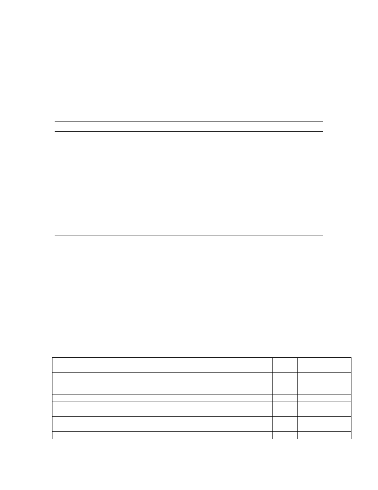
No. Item Symbol Term/Cond’n Value Unit
Min Typ. Max
1 Panel Driver Circuit
Voltage
Voltage Vs 165+10xVrs 165 - 185 V
Ripple/Noise Vnrs - - 500 mV
Stability - - - +/- 1.5 %
Setting accuracy - - - +/- 0,5 %
Current (average) Is APC function operation - - 1.5 A
Current (instant) Isp - - 12 A
2 Address Driver Circuit
Voltage
Voltage Va 55+10xVra 55 - 65 V
Ripple/Noise Vnrs - - 500 mV
Stability - +/- 1.5 %
Setting accuracy - +/- 0,5 %
Current (average) Ia - - 1.8 A
Current (instant) Iap - - 3.0 A
3 Logic Circuit Voltage
Voltage Vcc Fixed 4,75 5,0 5,25 V
Ripple/Noise Vnrs - - 200 mVp-p
Current (average) Icc - - 5.0 A
Current (instant) Icp - - 5.0 A
1. PDP unit will not operate under the following conditions. When in this
condition, panel driver circuit current “Is” will be less than 50mA.
•= “Vcc” has not been applied to the PDP unit.
•= 2 second period from power on until all power supply voltages (Vs, Va,
and Vcc) have settled to normal operating levels.
•= “Vs” is outside of the standart range.
•= “Va” is outside of the standart range.
•= No vertical synchronous signal present at signal interface.
2. Reference voltage Vrs is the output from the PDP unit for “Vs” voltage setting.
3. Is current is automatically controlled to approximately 1.0A by the APC
(Automatic Power Control) function. However, at start-up (1 minute or less), it
can reach up to 4.0 A and then it goes down gradually to the convergent
value for about 3 minutes. The APC setting value on start-up is approximately
300W (APC start-up display load ratio is approximately 20%).
4. Reference voltag e Vra is the output from the PDP uni t for “Va” voltage setting.
5. Vrr is the sequence control voltage to Vs and Va. When Vrr is “Enable level”,
Vs and Va voltages are able to be input to the PDP unit. However, when Vrr
is “Disable level”, Vs and Va voltage should be deactivated.
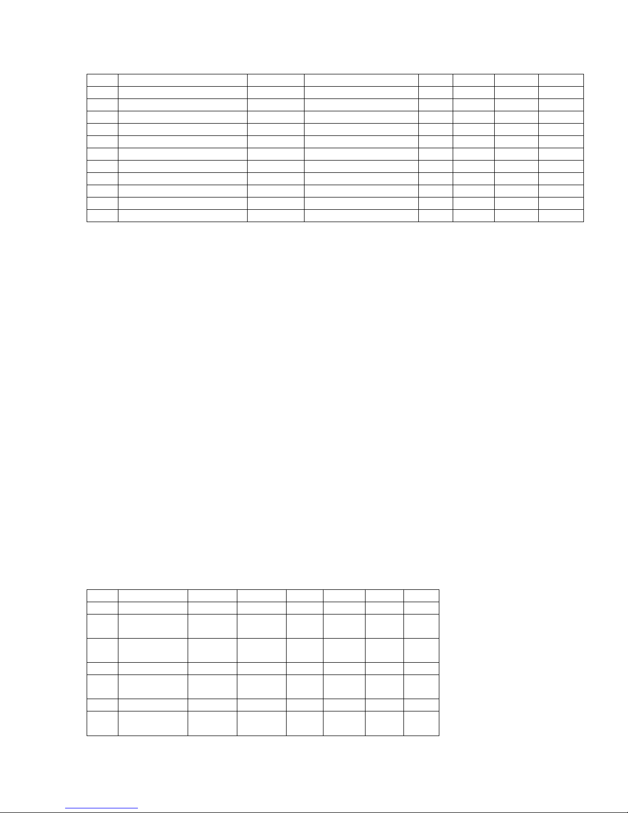
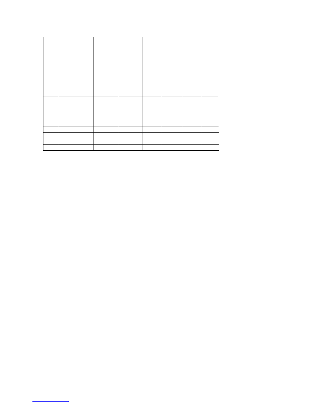
No. Item Symbol Cond’n Value Unit
Min. Typ. Max.
1 Vs setting
voltage
Voltage
(variable)
Ripple/Noise Vnrr - - +/-500 mV
Stability
(average)
Current Irs - - 3 mA
2 Va setting
voltage
Vrs 0.0 - 2.0 V
- - - +/- 0.2 %
Voltage
(Variable)
Ripple/Noise Vnrr - - +/-500 mV
Stability
(average)
Current Ira - - 3 mA
3 Sequence
conttrol high
voltage to Vs
and Va
Voltage
(Fixed)
Ripple/Noise Vnrr - - +/-500 mV
Stability
(average)
Current Irr - - 3 mA
Vra 0.0 - 2.0 V
- - - +/- 0.2 %
Vrr Enable
level
Disable
level
- - - +/- 0.2 %
2.0
0.0
-
-
3.5
1
V
V
1. Vrs is set at a value obtained from the following formula which is relative to
Vs.
Vs= 165+10xVrs [Vrs: 0 to 2.0V]
2. Vra is set at a value obtained from the following formula which is relative to
Va.
Va=55+10xVra [Vra: 0 to 2.0V]
3. When the PDP-unit is powered on, Vrr is output at a value of about 0V. Then
if Vs and Va are able to be input to the PDP-unit from 11PWB42 board, Vrr is
output at a value of about 3.0V.
4. Load resistor for each output signal are set at a value of 1kohm.
If it NEC panel,
If it NEC panel,
If it NEC panel,If it NEC panel,
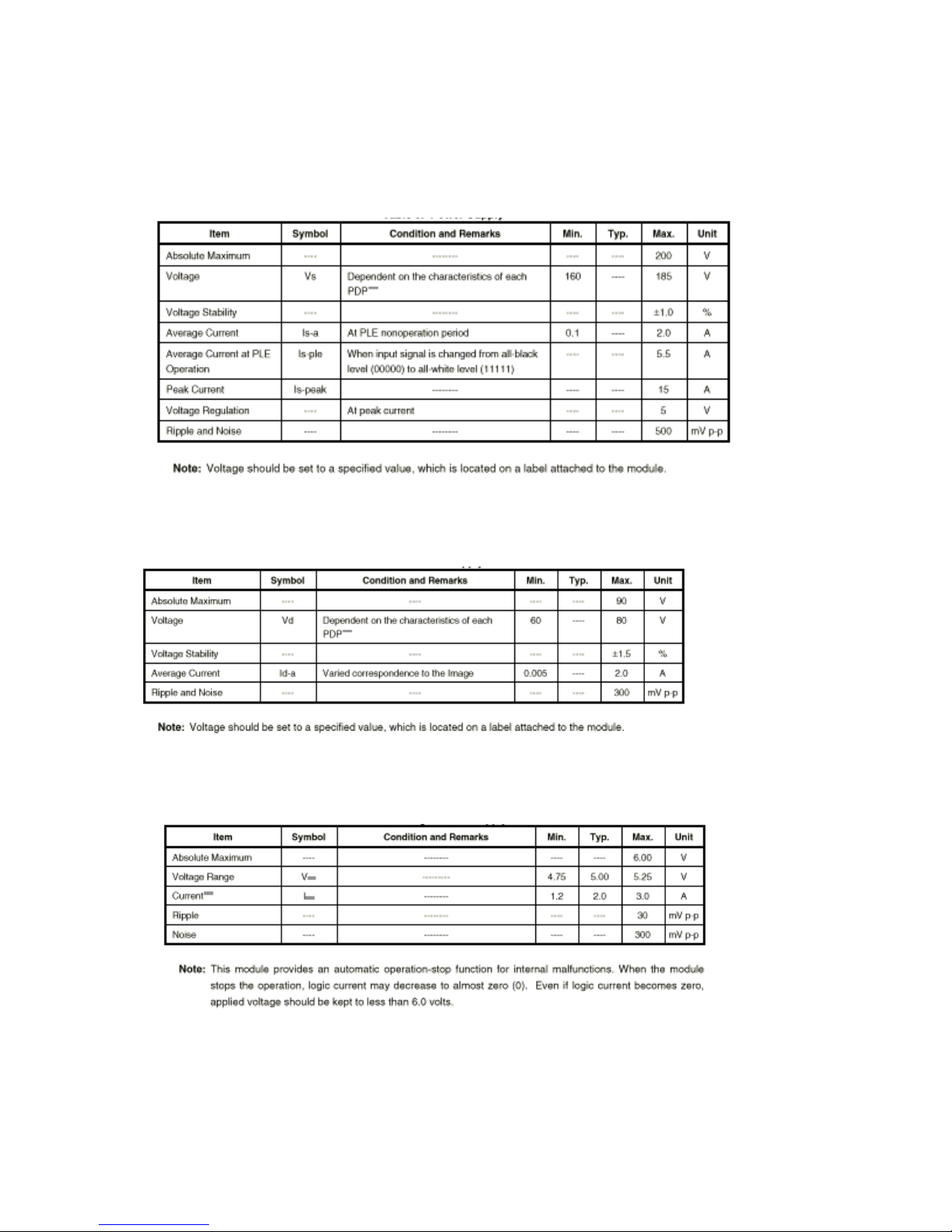
1. SUSTAIN POWER SUPPLY (Vs)
2. DATA POWER SUPPLY (Va)
3. LOGIC POWER SUPPLY
 Loading...