

VESTEL ANGELO FNPC12, ANGELO FNAC31, ANGELO FNAC13, ANGELO FNAC21, ANGELO FNAC41 Service Training
...Page 1
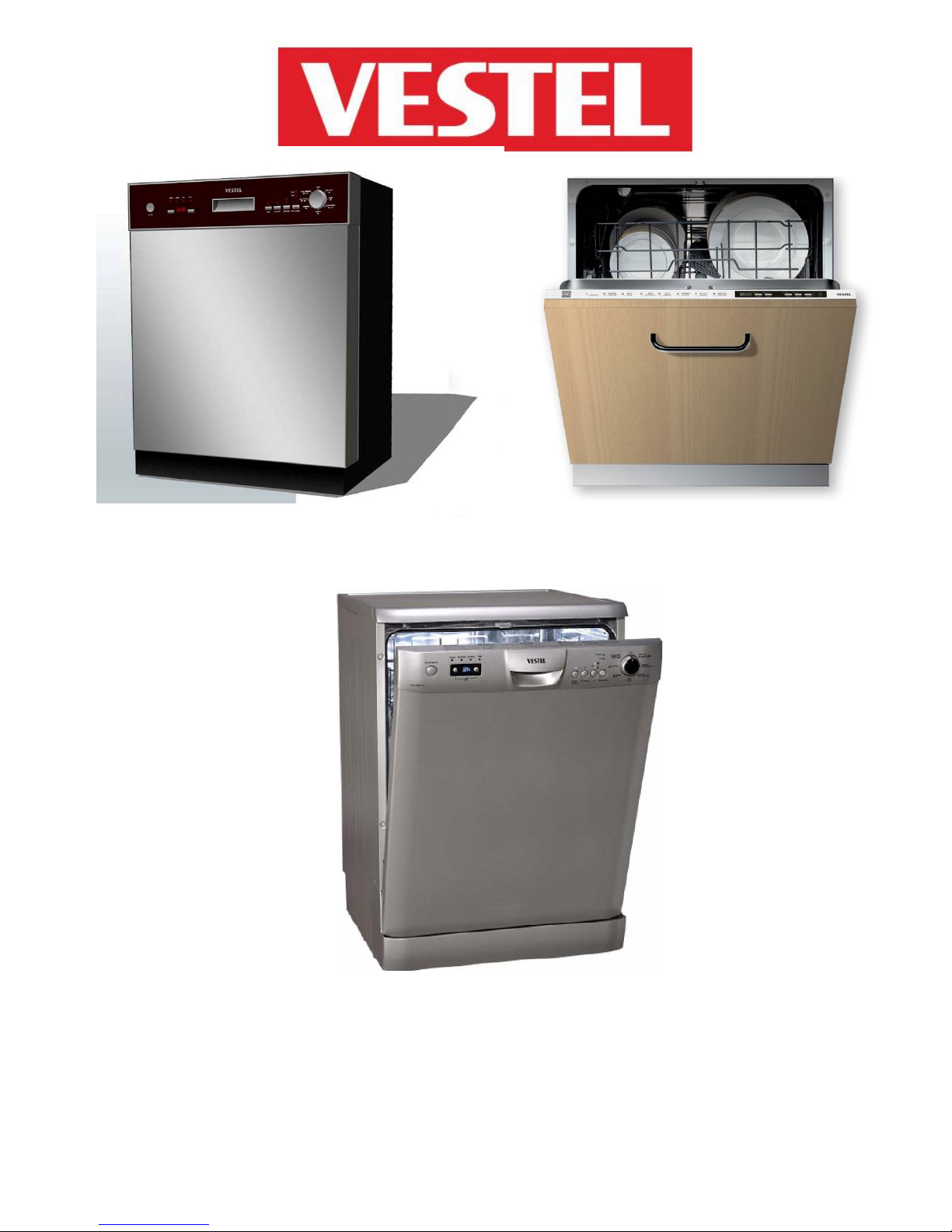
SEMI-INTEGRATED FULLY-INTEGRATED
FREE-STANDING
DISHWASHERS TRAINING DOCUMENT
- 1 -
Page 2
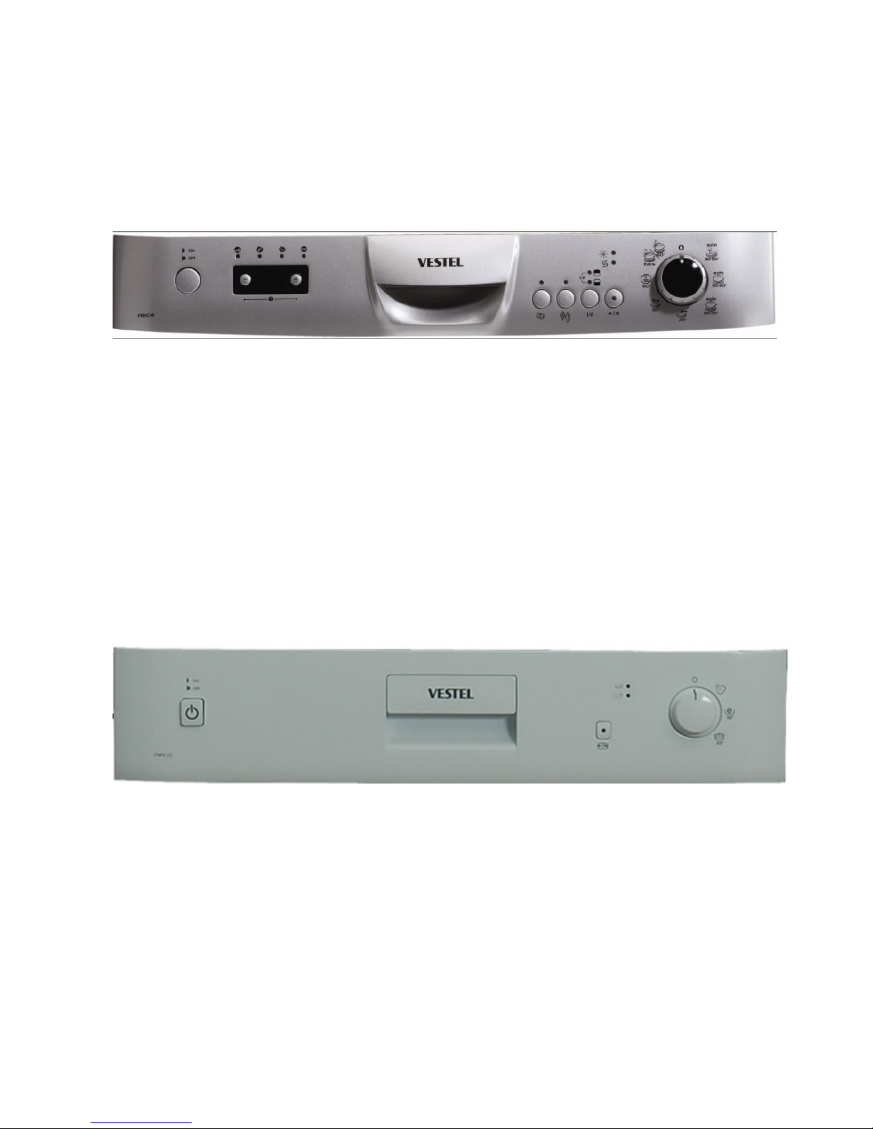
Vestel dishwashers are categorized into four series Angelo / Petra / Semi-Integrated and
Fully-Integrated.
Angelo / Petra / Semi_Integrated series have different panel versions. Fully-Integrated models
have built in adjustment mechanism and hinge spring adjustment mechanism.
A
NGELO SERIES
ANGELO classified;
• FNAC11
• FNPC12
• FNAC13
• FNAC21
• FNAC31
• FNAC41
They are produced 6 different versions.
PETRA SERIES
ETRA classified;
P
• FNPC11
• FNPC12
• FNPC13
• FNPC21
They are produced 4 different versions.
- 2 -
Page 3
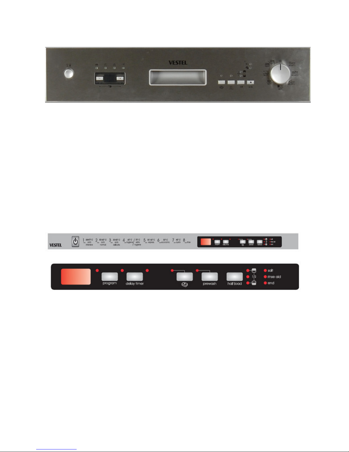
SEMI-INTEGRATED SERIES
Semı-Integrated classified;
• SNSC11
• SNSC13
• SNSC31
• SNSC41
They are produced 4 different versions.
FULLY-INTEGRATED SERIES
ully –Integrated classified;
F
• INRD13
• INRD21
• INRD41
They are produced 3 different versions.
- 3 -
Page 4
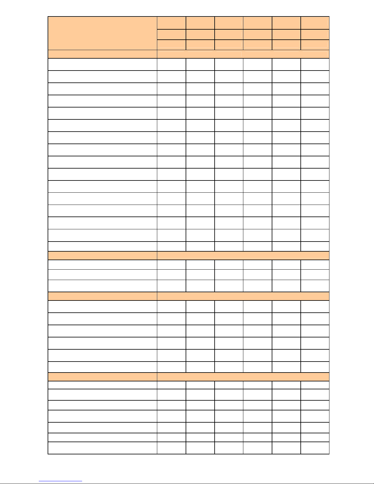
C11 C12 C13 C21 C31 C41
Models
General Features
Place-Settings Capacity 12 12 12 12 12 12
Colour White White White White White White
Programmes 2 3 4 6 7 9
Prewash - Yes Yes Yes Yes Yes
Economic 50°C Yes Yes Yes Yes Yes Yes
Normal - - - Yes Yes -
Automatic- Delicate 30-50°C - - - - - Yes
Automatic Normal 50-60°C - - - - - Yes
Automatic Intensive 60-70°C - - - - - Yes
Super/Intensıve program 65°C Yes Yes Yes Yes Yes -
Extra Intensıve program70° C
(Prewash+Intensıve 65°)
Hygiene 60°C - - - - - Yes
SNSC11 SNSC13 SNSC31 SNSC41
IND13 IND21 IND41
- - - Yes Yes -
Extra Hygiene 70°C (Prewash + Hygiene 60°C) - - - - - Yes
Quick program 30' 40°C - - Yes Yes Yes Yes
Delicate program 40°C - - - - Yes -
Super Program 55' 60°C - - - - - Yes
Functions
Tablet detergent - - - - - Yes
Prewash - - - Yes Yes Yes
1/2 Load - - - - Yes Yes
Indicators
Rinse-Aid Indicator - - - Yes Yes Yes
Salt Indicator - - - Yes Yes Yes
Fallowing Programme Indicator Yes Yes Yes Yes Yes Yes
Set the Time - - - Yes Yes Yes
Remaining Time Indicator - - - - - Yes
Child Lock - - - Yes Yes Yes
Baskets
Top basket height adjustment while it is full - - - - Yes Yes
Top basket height adjustment while it is empty - - - Yes - -
Lower Basket Folding Racks - - 2 pieces 4 pieces 4 pieces 4 pieces
Lower Basket Handle - - - Plastic Plastic Plastic
Upper Basket Handle - - - - - Plastic
Sensor - - - - Yes
Drying System Normal Normal Normal Normal Normal
Drying with
Fan
- 4 -
Page 5
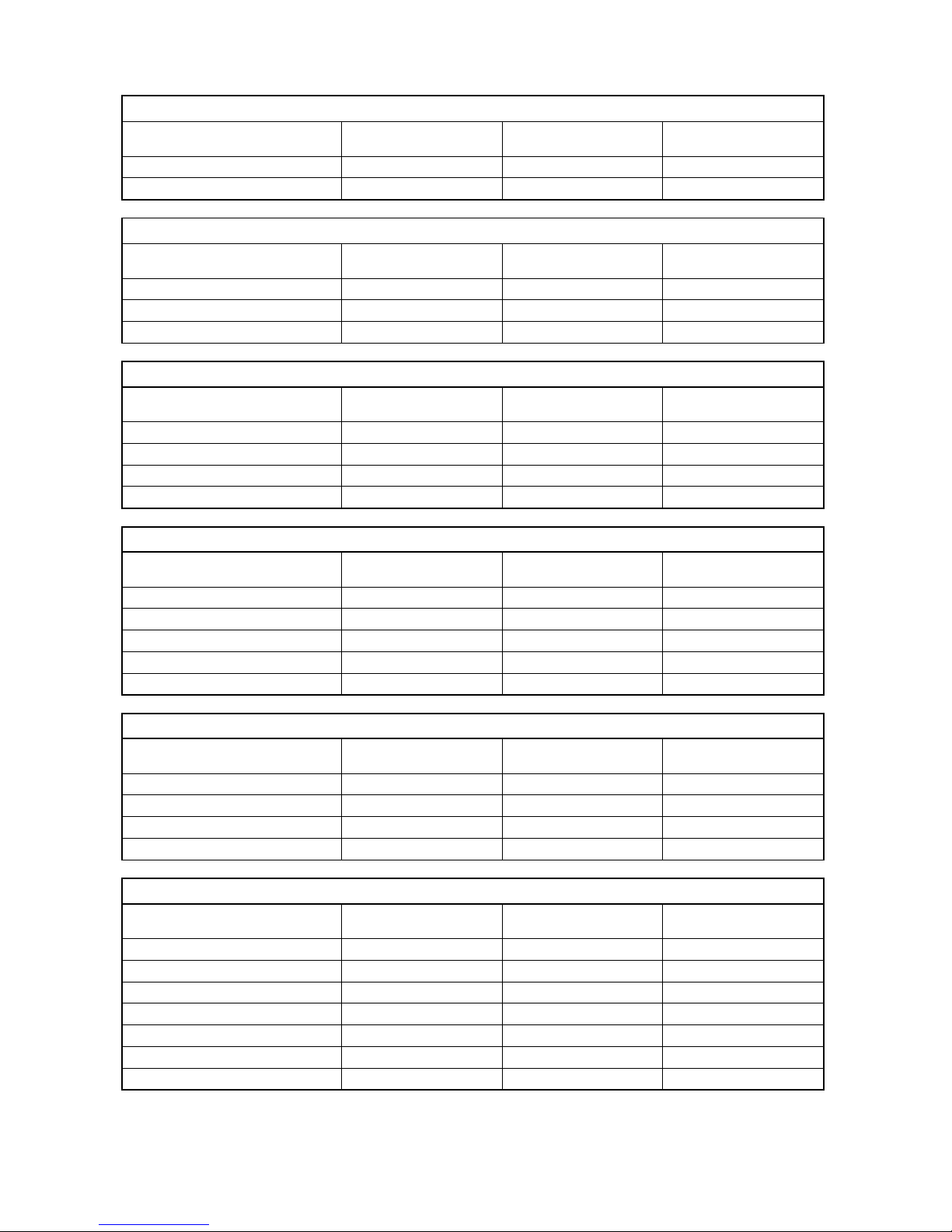
WATER AND ENERGY CONSUMPTIONS OF PROGRAMMES
FNAC11 - FNPC11- SNSC11
Water Consumption
Program Time (min )
Economic 50°C 150 15,7 1,05
Intensive 65°C 110 17,2 1,55
( lt )
FNAC12 - FNPC12
Water Consumption
Program Time ( dk )
Prewash 15 4,5 0,02
Economic 50°C 150 15,7 1,05
Intensive 65°C 110 17,2 1,55
( lt )
FNAC13 - FNPC13 - SNSC13 - INRD13
Water Consumption
Program Time ( min )
Prewash 15 4,5 0,02
Quick 40°C 30 12,4 0,68
Economic 50°C 150 15,7 1,05
Intensive 65°C 110 17,2 1,55
( lt )
Energy
Consumption( kWh )
Energy
Consumption( kWh )
Energy
Consumption( kWh )
FNAC21 - FNPC21 - INRD21
Water Consumption
Program Time ( min )
Prewash 15 4,5 0,02
Quick 40°C 30 12,4 0,68
Economic 50°C 150 15,7 1,05
Normal 55°C 95 16,5 1,1
Intensive 65°C 110 17,2 1,55
( lt )
Energy
Consumption( kWh )
FNAC21 - FNPC21 - INRD21(With Prewash Option Selected)
Water Consumption
Program Time ( min )
Quick 40°C + Prewash 45 16,9 0,7
Economic 50°C+ Prewash 165 20,2 1,07
Normal 55°C + Prewash 110 21 1,12
Extra Intensive 150 25,7 1,57
( lt )
Energy
Consumption( kWh )
FNAC31 - FNPC31 - SNSC31
Water Consumption
Program Time ( min )
Prewash 15 4,2 0,02
Quick 40°C 30 10,9 0,65
Delicate 40°C 70 13,8 0,79
Economic 50°C 165 13,4 1,05
Normal 55°C 105 14,7 1,5
Intensive 65°C 110 16,4 1,55
Extra Intensive 150 20,1 1,9
- 5 -
( lt )
Energy
Consumption( kWh )
Page 6
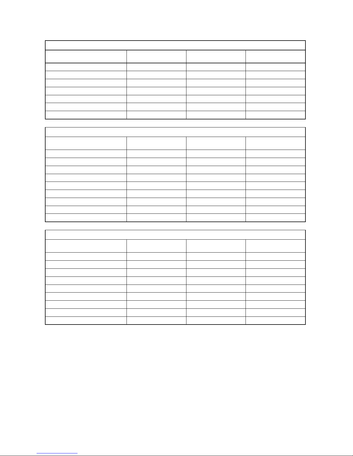
FNAC31 - FNPC31 - SNSC31 (With Half Load Option Sele
Water Consumption
Program Time ( min )
Prewash 15 4,2 0,02
Quick 40°C 30 10,9 0,72
Delicate 40°C 62 10 0,80
Economic 50°C 155 9,6 1,03
Normal 55°C 97 10,5 1,13
Intensive 65°C 88 11,8 1,27
Extra Intensive 122 15,5 1,59
( lt )
cted)
Energy
Consumption( kWh )
FNAC41 - FNPC41 -SNSC41- INRD41
Water Consumption
Program Time ( min )
Prewash 15 4,2 0,02
Automatic Delicate 30-50°C 64 - 92 10.6 - 17.7 0.60 - 0.80
Automatic Normal 50-60°C 100 - 127 10.9 - 18.5 1,03 – 1,28
Automatic Intensive 60-70°C 111 - 183 13.3 - 24.6 1.25 – 1,78
Quick 40°C 30 11 0,71
Economic 50°C 170 13,5 1,05
Super 55 min 60°C 55 11 0,93
Hygiene 60°C 119 15 1,55
Extra Hygiene 161 22,7 1,75
( lt )
Energy
Consumption( kWh )
FNAC41 – FNPC41 -SNSC41- INRD41 (With Half Load Option Selected)
Water Consumption
Program Time ( min )
Prewash 15 4,2 0,02
Automatic Delicate 30-50°C 62 – 81 9.9 - 13.7 0.79 – 0.94
Automatic Normal 50-60°C 85 - 107 10.5 - 14.3 1.1 - 1.28
Automatic Intensive 60-70°C 113 - 163 11.9 - 19.9 1.20 - 1.77
Quick 40°C 30 11 0,72
Economic 50°C 153 9,8 1,03
Super 55 min 60°C 55 11 1,07
Hygiene 60°C 95 10,5 1,25
Extra Hygiene 130 18,2 1,38
( lt )
Energy
Consumption( kWh )
Not: The values declared above are the values obtained under laboratory conditions
according to the relevant standards.
These values can change depending on environment and product’s usage conditions.
(network tension, water input temperature and environment)
- 6 -
Page 7
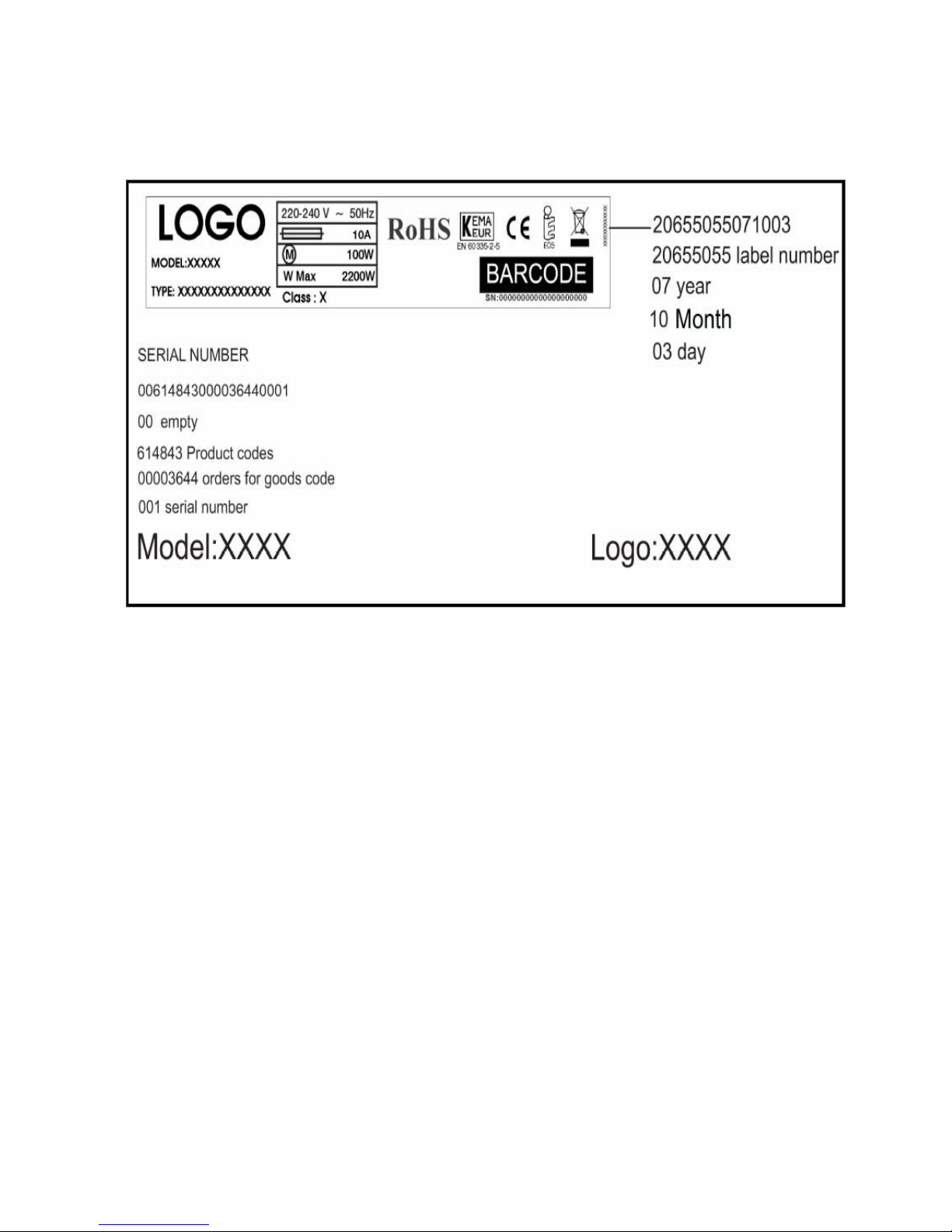
NAME PLATE
- 7 -
Page 8
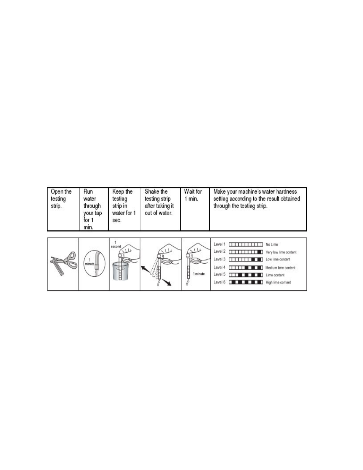
SETTING THE WATER HARDNESS
T
est strip;
The washing effectiveness of your machine depends on the softness of the tap water. For
this reason, your machine is equipped with a system that reduces the hardness in mains
water supply. The washing effectiveness will increase when the system is correctly set. To
make the system setting, use the testing strip, if it is available, and find the hardness of the
mains water supply.
- 8 -
Page 9
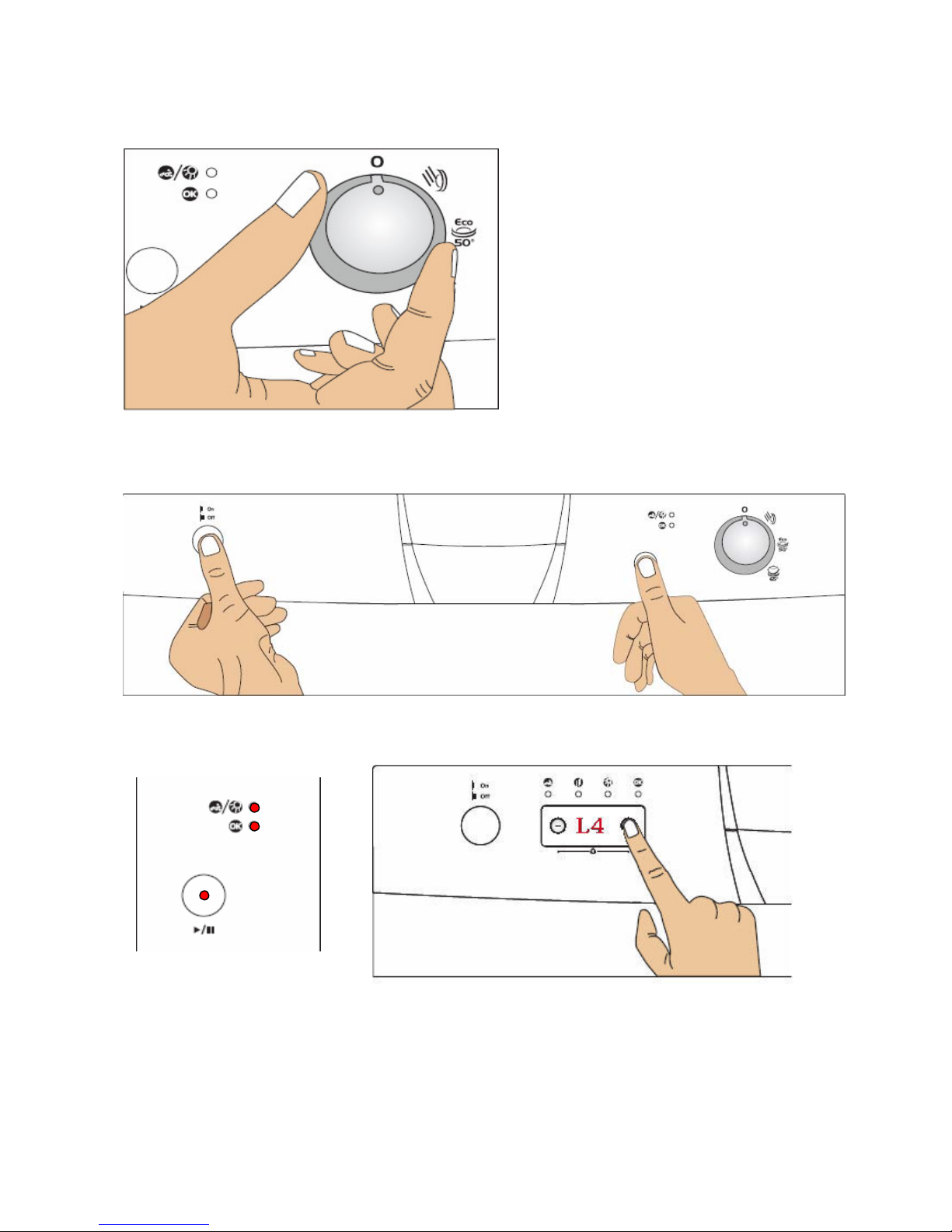
For Free Standing and Semi- Integrated Models;
a
) Move the programme selector knob to the 0(reset) position while your machine is not in
operation.
b) Press the Start/Pause button and keep it pressed down. Meanwhile, energise the machine
by pressing the Power On/Off button.
c) Keep Start/Pause button pressed until program monitor lights are on and off.
d) After the lights have flashed, release the Start/Pause button.
Your machine displays the latest entered water hardness setting.You can adjust the
levels by pressing Start/Pause button according to the table of Water Hardness Level
Settings. You can adjust tle levels by pressing “+” and “-“ buttons placed on display in
FNAC31 and FNAC41 models.
- 9 -
Page 10
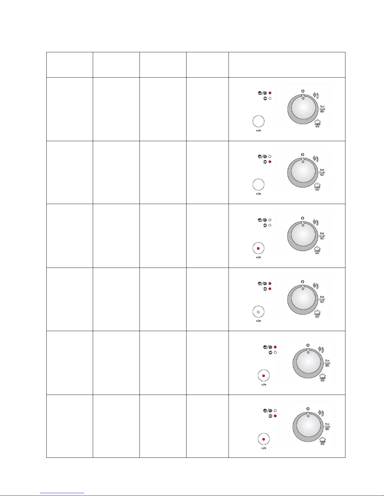
Water
Hardness
Level
C11, C12, C13
Water Hardness Level Indicators
German
Hardness
dH
French
Hardness
dF
British
Hardness
dE
HARDNESS LEVEL
INDICATORS
1 0-5 0-9 0-6
2 6-11 10-20 7-14
3 12-17 21-30 15-21
4 18-22 31-40 22-28
5 23-31 41-55 29-39
6 32-50 56-90 40-63
- 10 -
Page 11
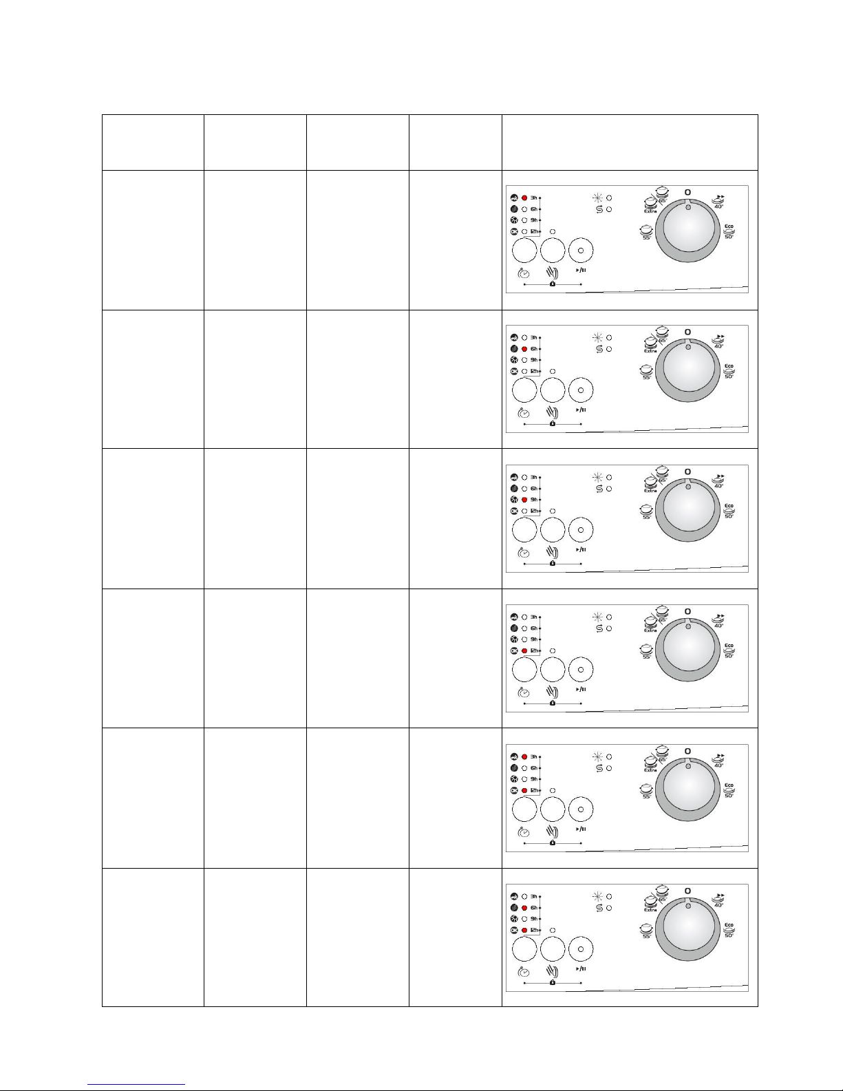
Water
Hardness
Level
C21, C31
Water Hardness Level Indicators
German
Hardness
dH
French
Hardness
dF
British
Hardness
dE
HARDNESS LEVEL
INDICATORS
1 0-5 0-9 0-6
2 6-11 10-20 7-14
3 12-17 21-30 15-21
4 18-22 31-40 22-28
5 23-31 41-55 29-39
6 32-50 56-90 40-63
- 11 -
Page 12
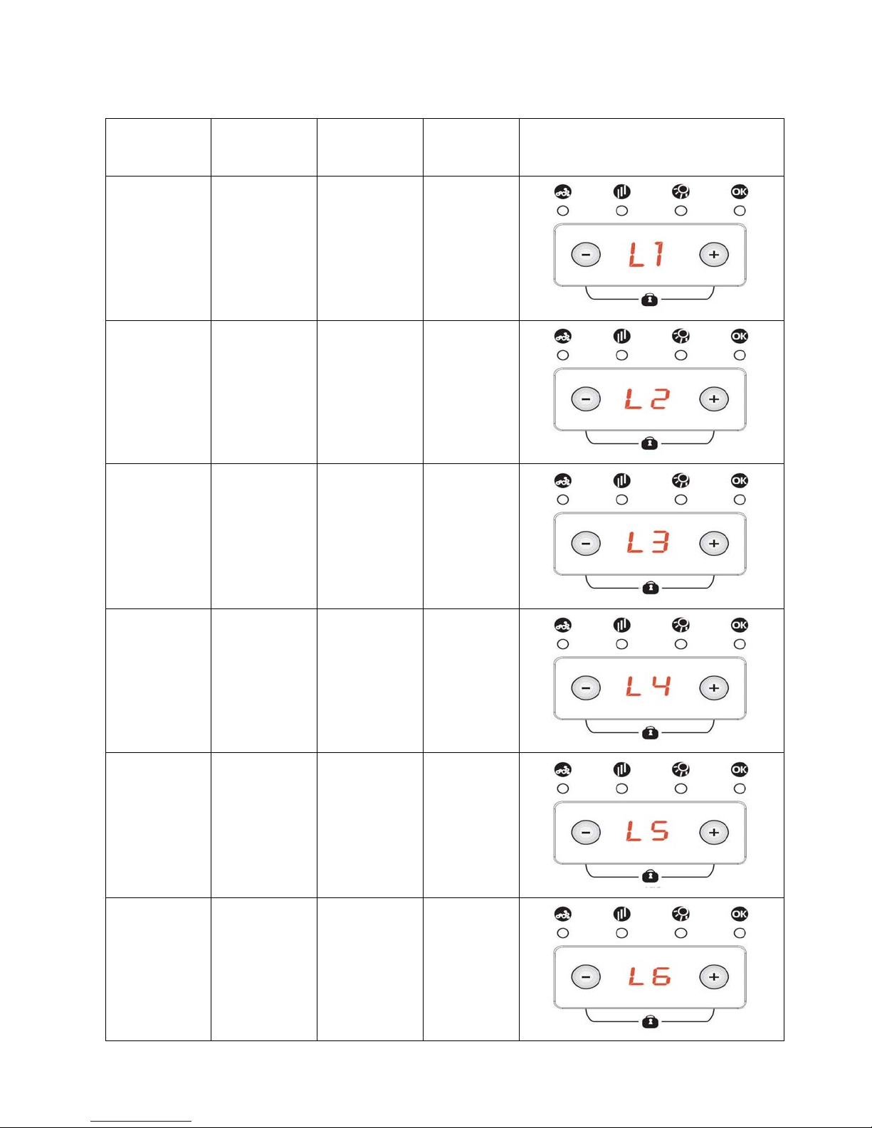
Water
Hardness
Level
C41
Water Hardness Level Indicators
German
Hardness
dH
French
Hardness
dF
British
Hardness
dE
HARDNESS LEVEL
INDICATORS
1 0-5 0-9 0-6
2 6-11 10-20 7-14
3 12-17 21-30 15-21
4 18-22 31-40 22-28
5 23-31 41-55 29-39
6 32-50 56-90 40-63
- 12 -
Page 13
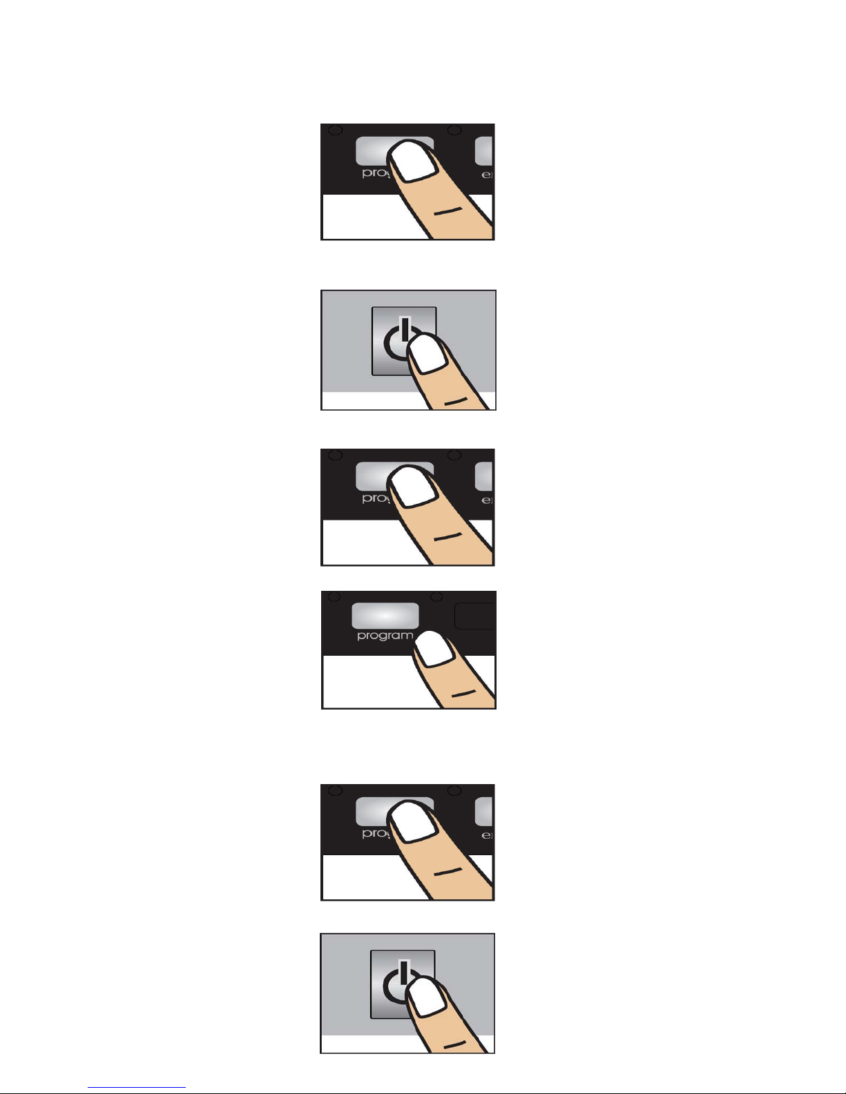
Fully-Integrated Models;
I
NRD 13
a) Press the Program selector button and keep it pressed down while your machine is not in
operation,
b) Meanwhile, energise the machine by pressing the On/Off button.
c) Keep Program selector button pressed until “P1– P2 – P3 – P4– End” lights are on andoff.
d) After the “P1– P2 – P3 – P4– End” have flashed, release the Program selector button.
Your machine displays the latest entered water hardness setting.
e) You can adjust the levels by pressing Program selector button according to the table of
Water Hardness Level Settings.
f)After adjusting the water hardness level, press on/off button to save settings in memory.
- 13 -
Page 14
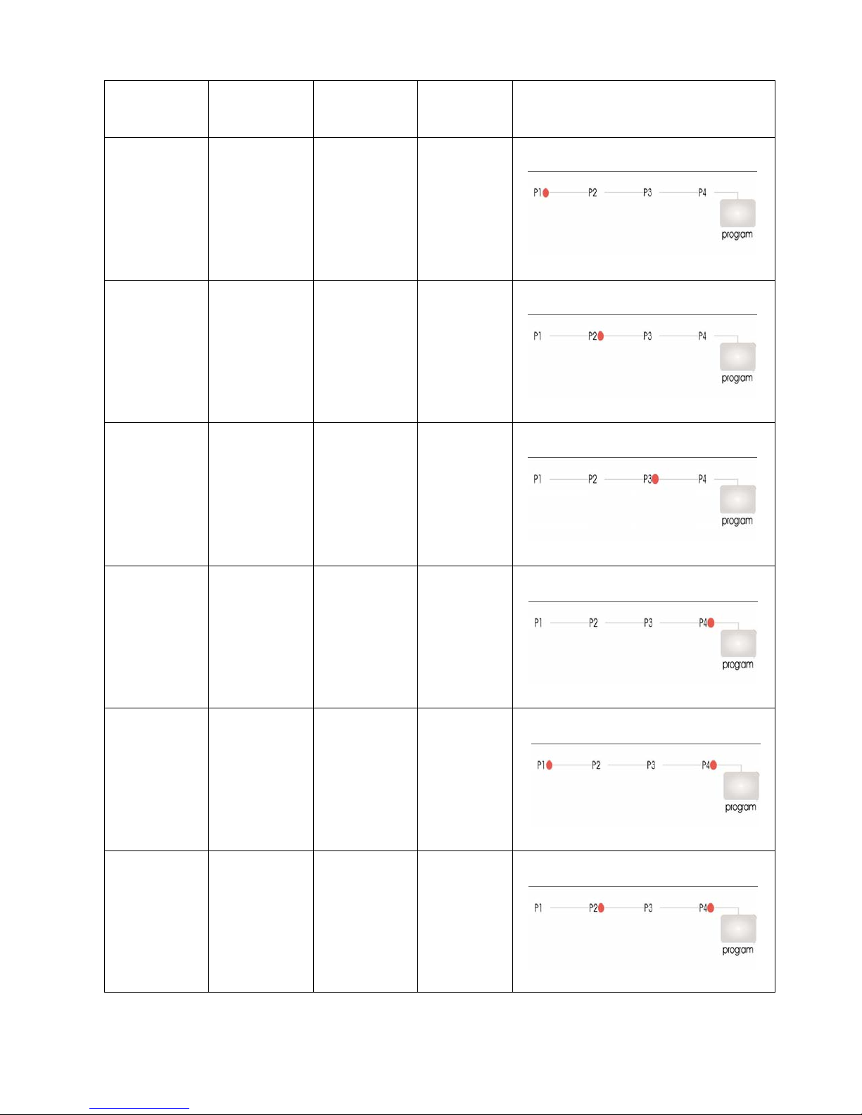
INRD 13
W
ater
Hardness
Level
German
Hardness
dH
French
Hardness
dF
British
Hardness
dE
HARDNESS LEVEL
INDICATORS
1 0-5 0-9 0-6
2 6-11 10-20 7-14
3 12-17 21-30 15-21
4 18-22 31-40 22-28
5 23-31 41-55 29-39
6 32-50 56-90 40-63
- 14 -
Page 15
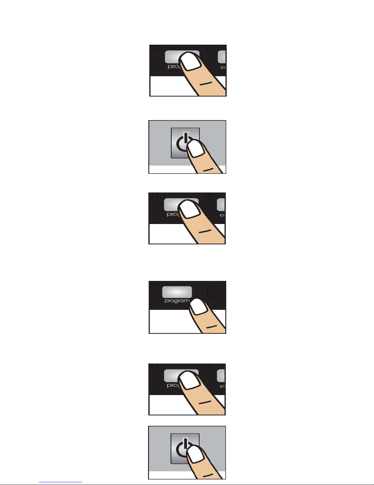
INRD21
a) Press the Program selector button and keep it pressed d
operation,
b) Meanwhile, energise the machine by pressing the O
c) Keep Program selector button pressed until “P1– P2 – P3 – P4– P5– 3h –6h– 9h– End”
lights are on and off.
d) After the “P1– P2 – P3 – P4– P5– 3h –6h– 9h– End” have flashed, release the Program
selector button.
Your machine displays the latest entered water hardness setting.
e) You can adjust the levels by pressing Program selector button according to the table of
Water Hardness Level Settings.
f) After adjusting the water hardness level, press on/off button to save settings in memory.
- 15 -
own while your machine is not in
n/Off button.
Page 16
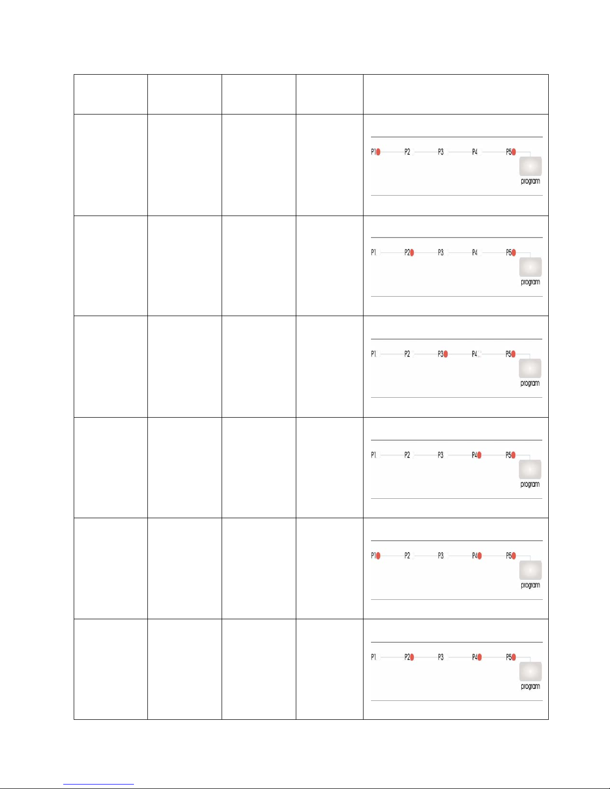
I
NRD21
Water
Hardness
Level
German
Hardness
dH
French
Hardness
dF
British
Hardness
dE
HARDNESS LEVEL
INDICATORS
1 0-5 0-9 0-6
2 6-11 10-20 7-14
3 12-17 21-30 15-21
4 18-22 31-40 22-28
5 23-31 41-55 29-39
6 32-50 56-90 40-63
- 16 -
Page 17
I
NRD41
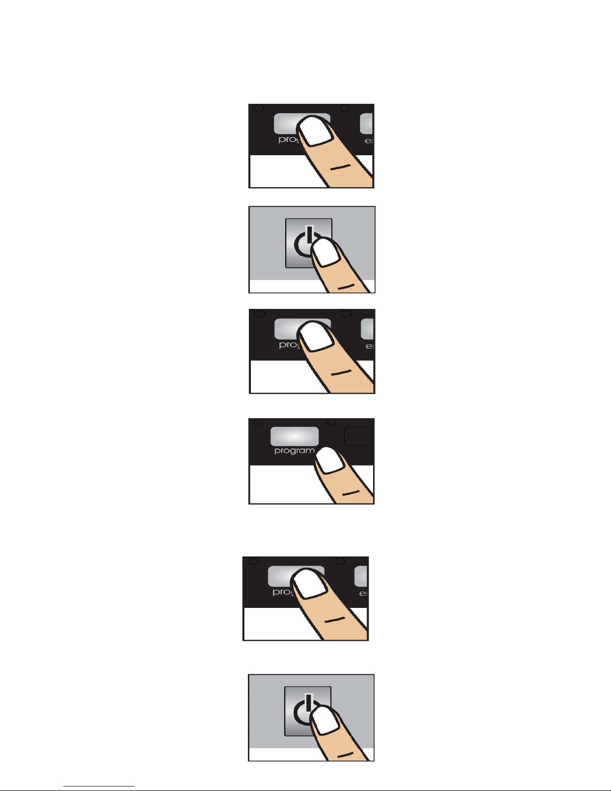
a) Press the Program selector button and keep it pressed down while your machine is not in
operation,
b) Meanwhile, energise the machine by pressing the On/Off button.
c) Keep Program selector button pressed until “SL” expression is on and off.
d) After the “SL” expression have flashed, release the Program selector button.
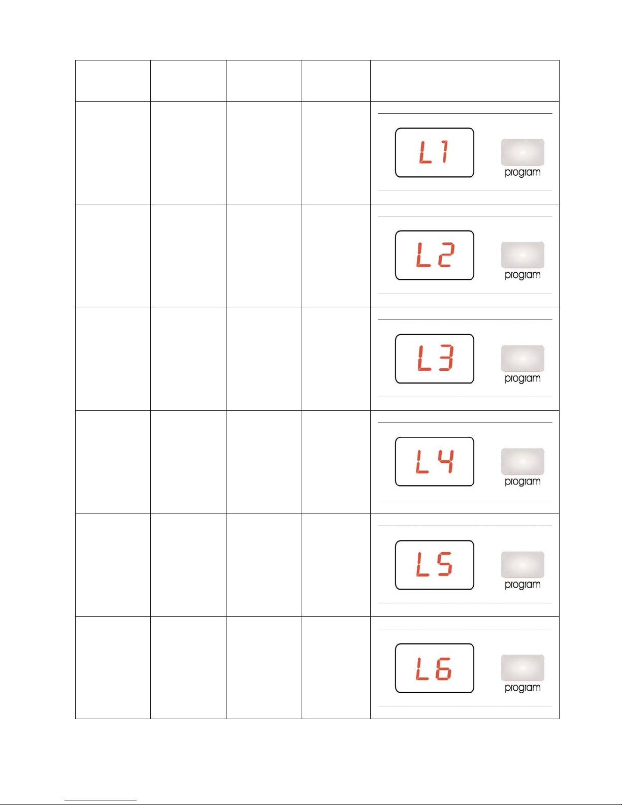
Your machine displays the latest entered water hardness setting.
e) You can adjust the levels by pressing Program selector button according to the table of
Water Hardness Level Settings.
f) After adjusting the water hardness level, press on/off button to save settings in memory..
- 17 -
Page 18
INRD41
Water
H
ardness
Level
German
Hardness
dH
French
Hardness
dF
British
Hardness
dE
HARDNESS LEVEL
INDICATORS
1 0-5 0-9 0-6
2 6-11 10-20 7-14
3 12-17 21-30 15-21
4 18-22 31-40 22-28
5 23-31 41-55 29-39
6 32-50 56-90 40-63
- 18 -
Page 19
Child Lock:
C21, C31 and C41 models
A
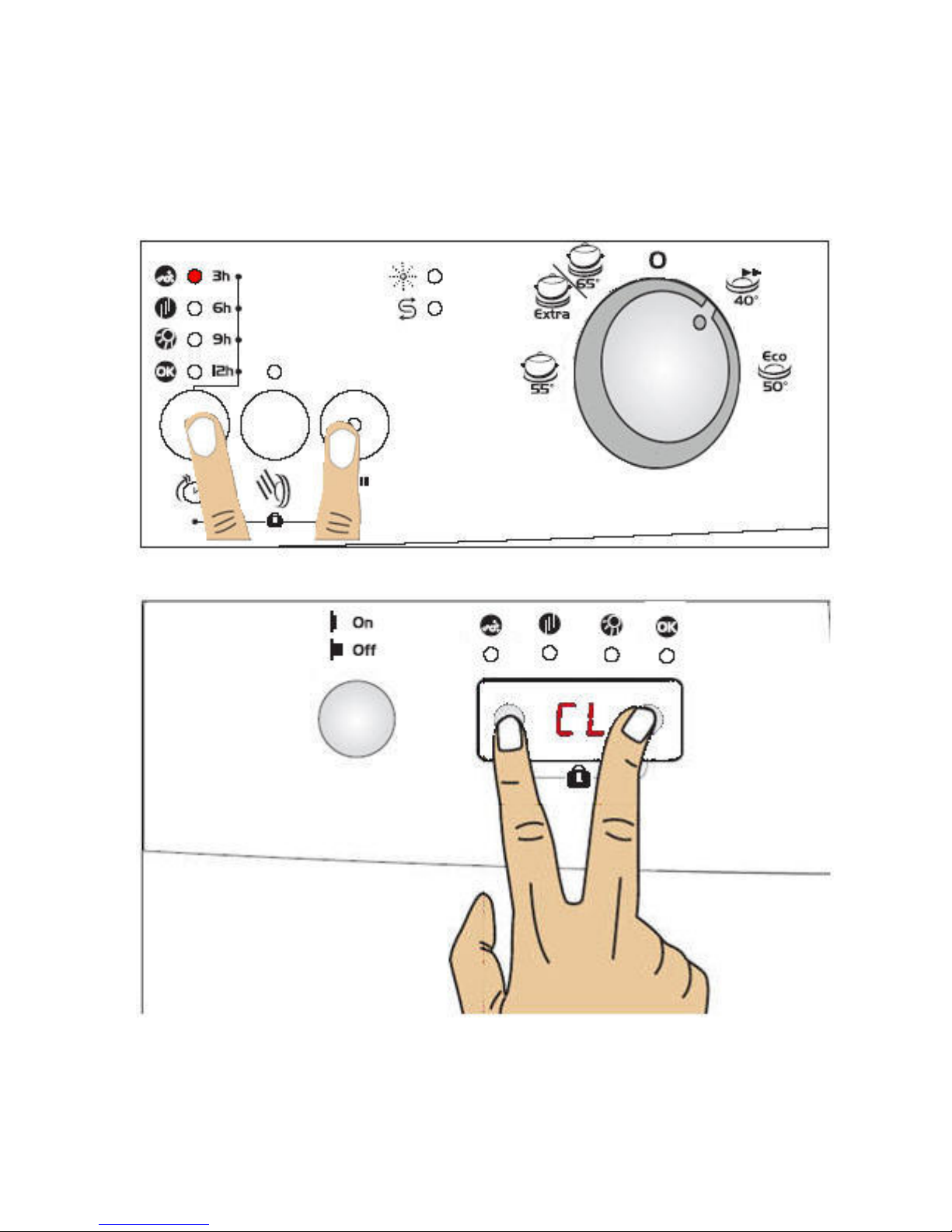
ctivate Child Lock: Press Start/Pause and Delay buttons simultaneously for 4 seconds. When
activated, 3h (washing) lamp flashes once. İn C41 model press “+” and “–” buttons on Remaining
time indicator simultaneously for 4 seconds. At this time, "CL" appears for 2 seconds on remaining
time indicator
Inactivate Child Lock: Press Start/Pause and Delay buttons simultaneously for 4 seconds. When
activated, 3h (washing) lamp flashes twice. In C41 model press “+” and “–” buttons again
simultaneously for 4 seconds. "CL" will blink for 2 times.
- 19 -
Page 20
Delay Timer:
C21 and C31,
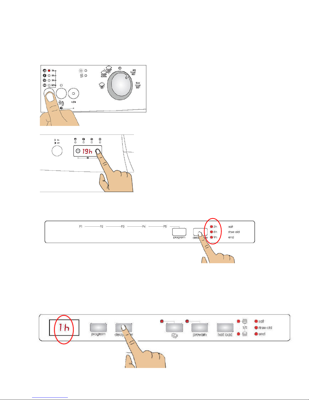
When you press delay button, 3h (washing) lamp flashes.If you continue pressing delay
button, 6h-9h-12h lamb will flash respectively for each press. If you select delay time and
press Start/Pause button, then you activate delay time.
C41
In these models you can select the delay
time by pressing “+” and “–” buttons on
display. For activating delay time press
Start /Pause button.
IND21
When you press delay button, 3h lamp flashes. If you continue pressing delay button, 6h-9h
lamb will flash . If you press delay button again ,after 9h lamb flashed , delay will reset. You
may select the delay time, after selecting the programme.
IND 41
When you press delay button,"1h" appears on program display. If you continue pressing
delay button, 1h-2h-...19h lamb will flash respectively for each pressing. You may select the
delay time, after selecting the programme. For changing or resetting delay time , adjust the
new time by pressing delay button. It will active according to the latest entered setting.
- 20 -
Page 21
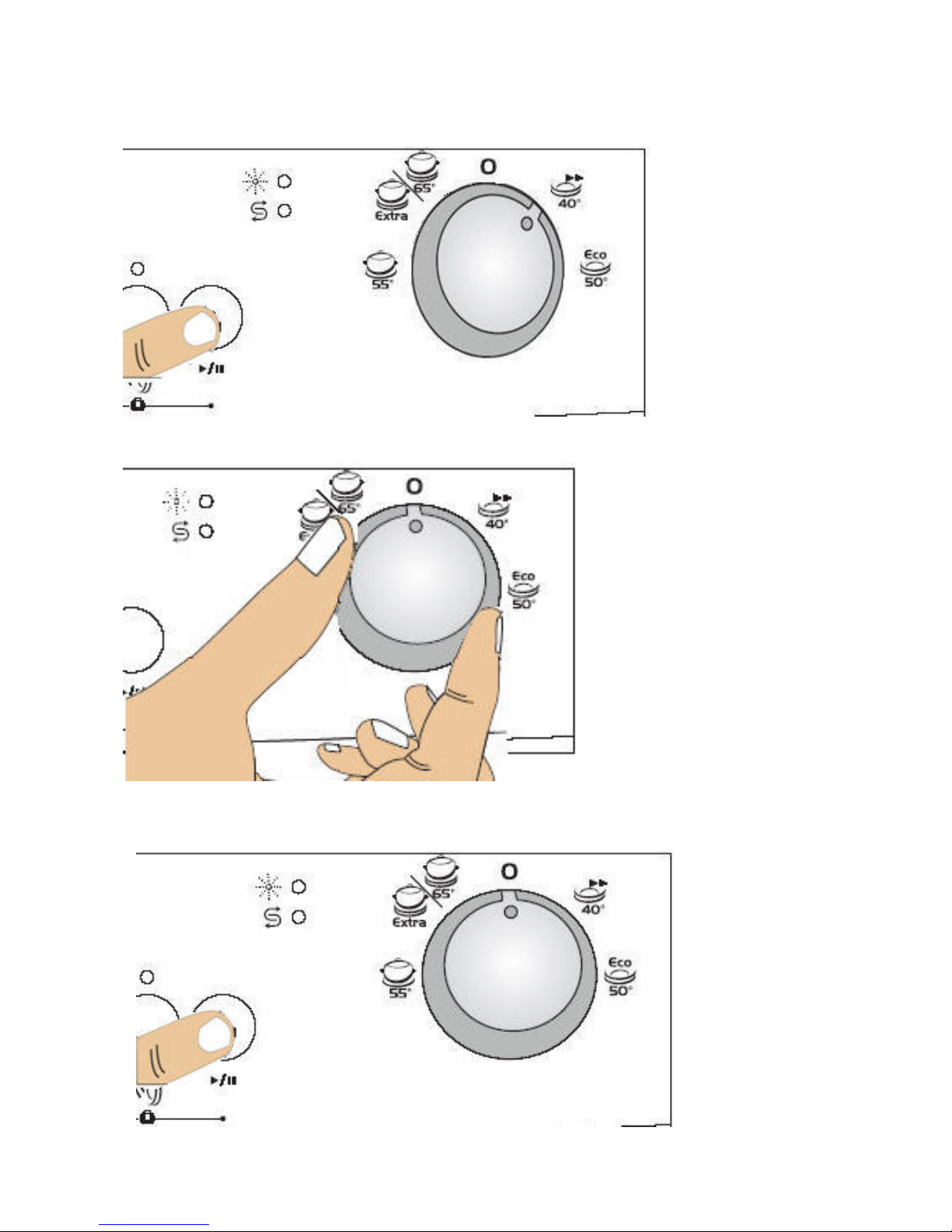
Program resetting;
F
or Free-Standing and Semi-Integrated Models,
a) Press Start/Pause button.
b) Turn the Program Selection Button to Reset.
c) Press once the Start/Pause button. The machine will drain the water in it for nearly 30
sec.When the end lamb is on, the program will have been cancelled.
- 21 -
Page 22
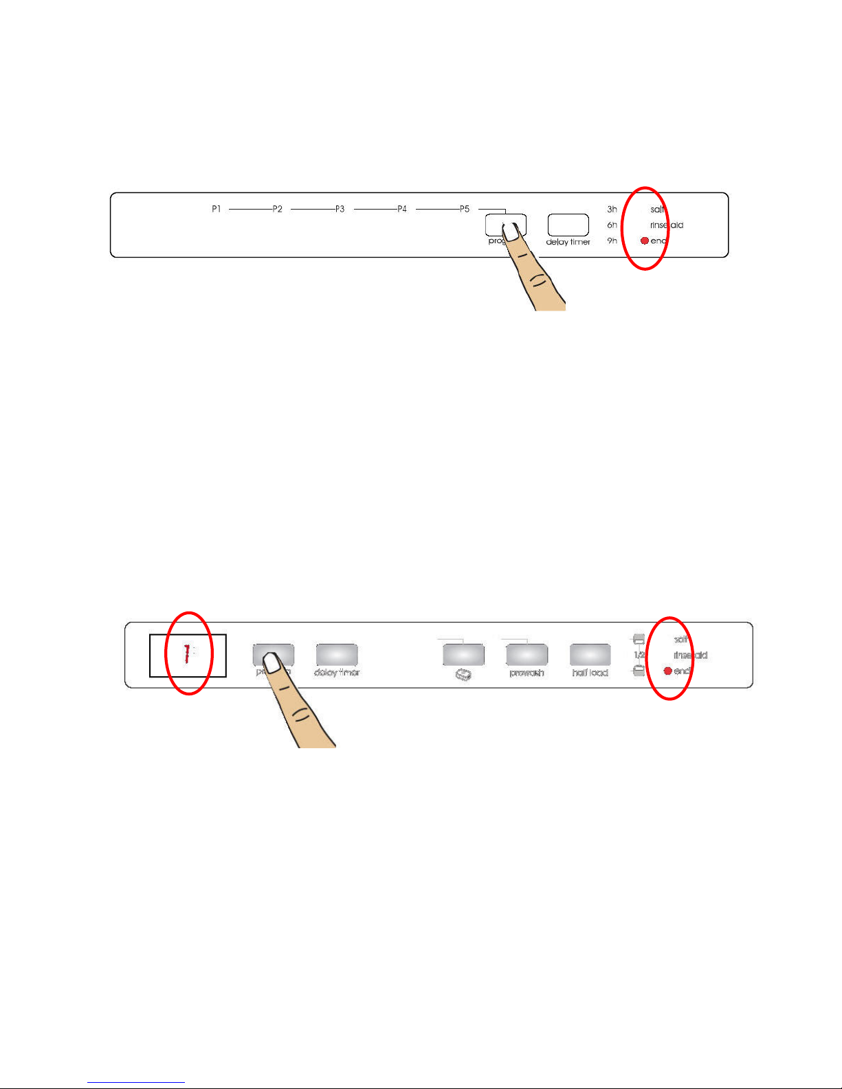
Fully-Integrated Models,
IND13 ve IND21 Models,
a
) If you want to reset the program while your machine is working, open the door and press
program button along 3sec (until end lamb is highlightened) ,
b. After closing the door, draining will start. The machine will drain the water in it for nearly 30
sec. When the program is cancelled, tha machine signals and end lamb is on.
IND41
a) If you want to reset the program while your machine is working, open the door and press
program button along 3sec (until ‘’1’’ appears on dispaly),
b) After closing the door, draining will start. The machine will drain the water in it for nearly 30
sec. When the program is cancelled, tha machine signals and end lamb is on.
- 22 -
Page 23
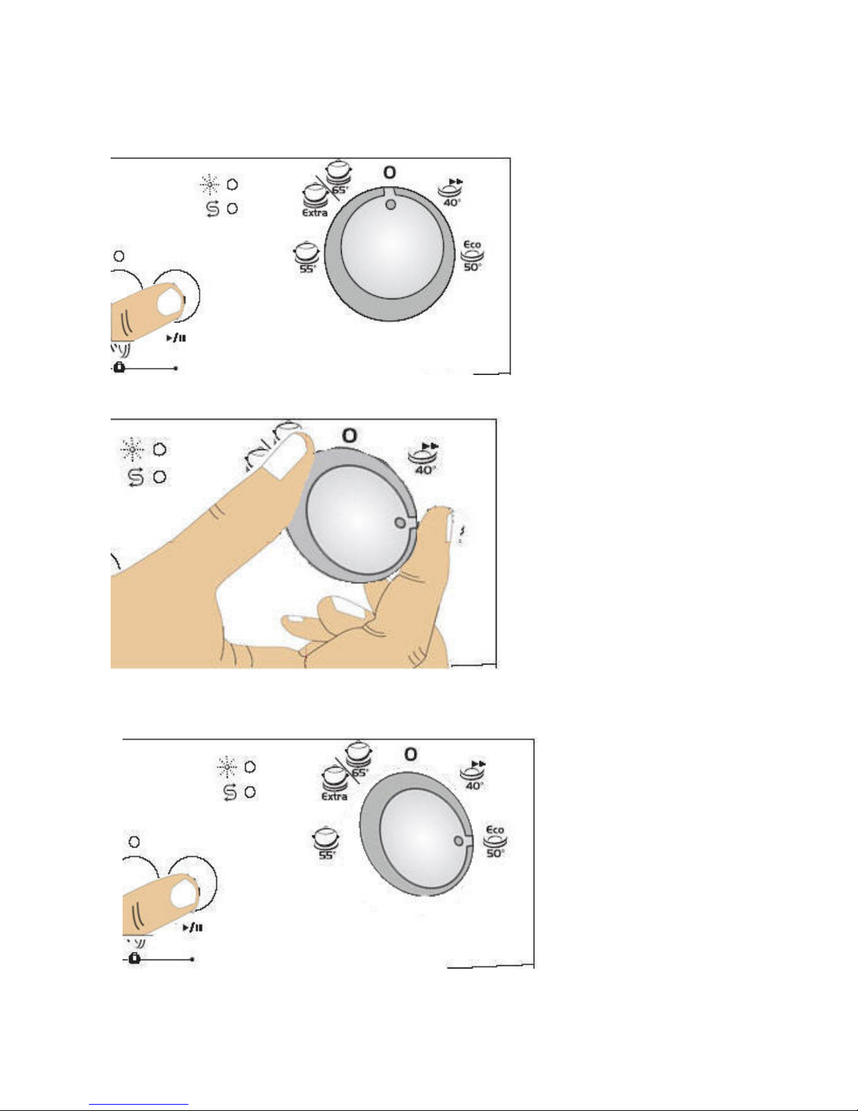
Changing A Program ;
F
or Free-Standing and Semi-Integrated Models,
a) Press Start/Pause button.
b) After the program stops select your desired program via the Program selection button.
c) Start the program you have newly selected by pressing again Start/Pause button. The
new program started will resume the course of the old program.
- 23 -
Page 24
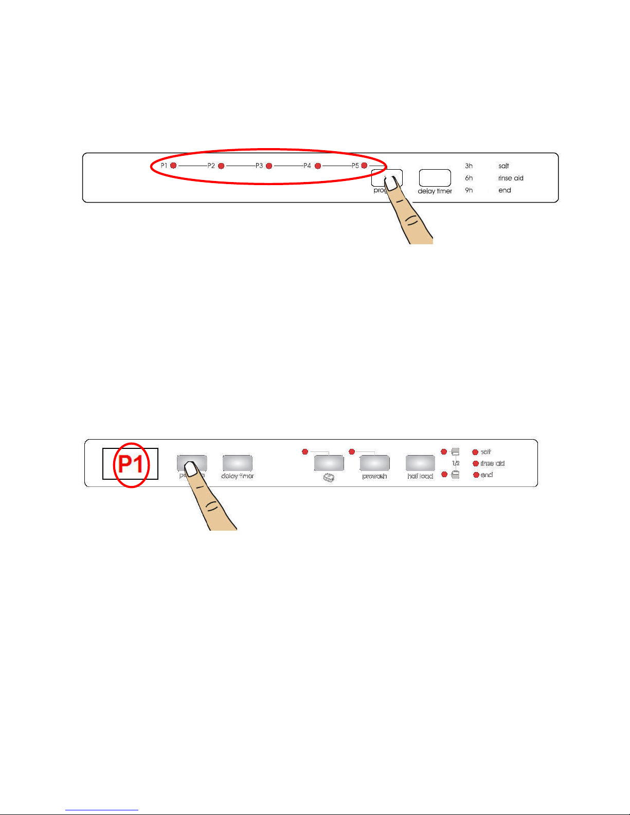
Fully-Integrated Models,
I
ND13 and IND21 Models
a) Open the door and select your desired program via the Program selection button,
b)The new program started will resume the course of the old program.
IND41 Model
a) Open the door and select your desired program via the Program selection button,
b) The new program started will resume the course of the old program.
- 24 -
Page 25
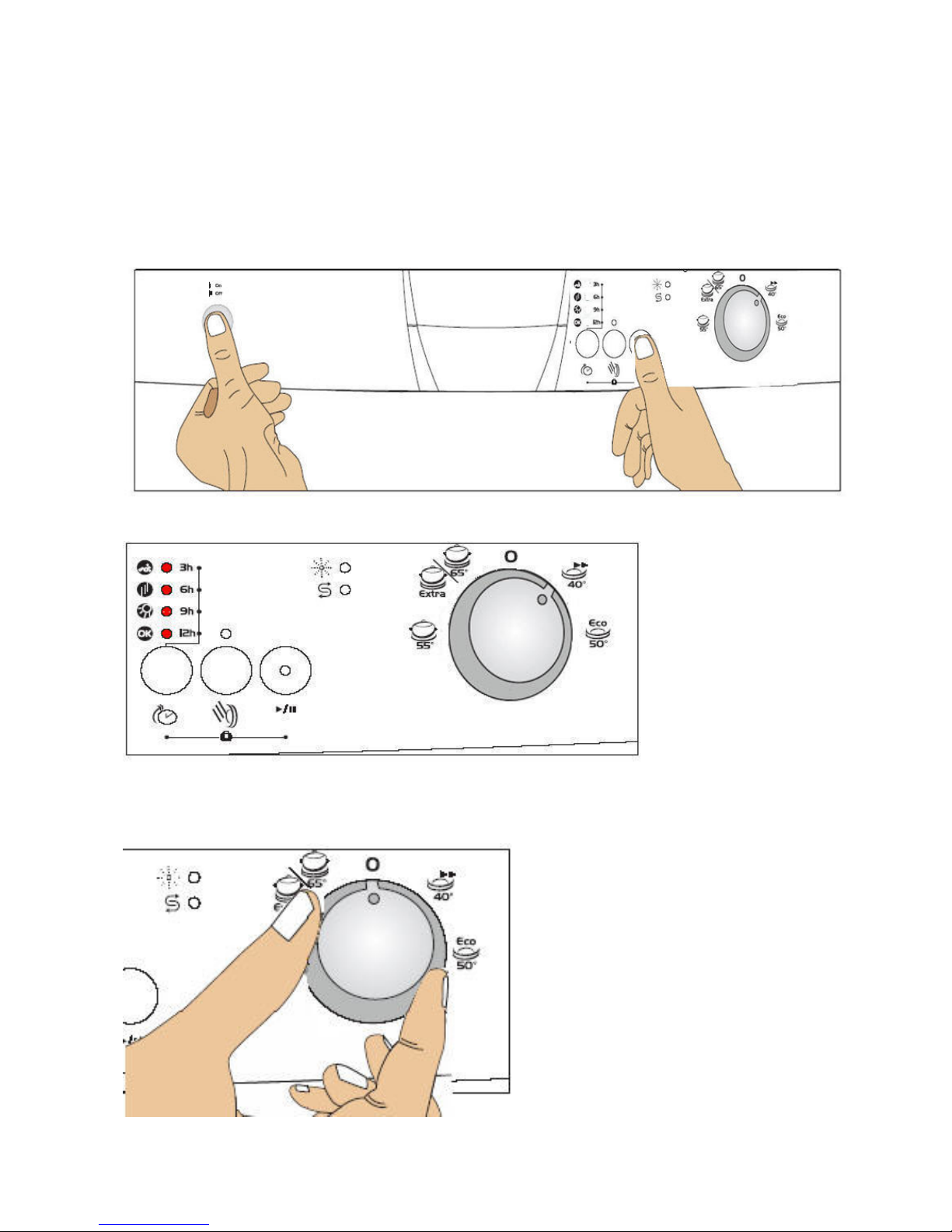
SERVICE TEST PROGRAMME
For Free-Standing and Semi-Integrated Models,
First of all be sure that the machine isn’t in ope
a) Move the programme selector knob to the first programme placed the right of reset
and press the start/pause button while your machine is not in operation. Keep the start
pause button pressed down meanwhile energise the machine by pressing the on/off button.
b) Keep the start/pause button pressed until the flow indicators are on and off. It takes ~5sec.
c) After the flow indicators are on and off, move the programme selector knob to the reset
position. Keep the start/pause button pressed again until the flow indicators are on and off
.
After finalizing the above processes; the service program starts automatically.
- 25 -
ration.
Page 26
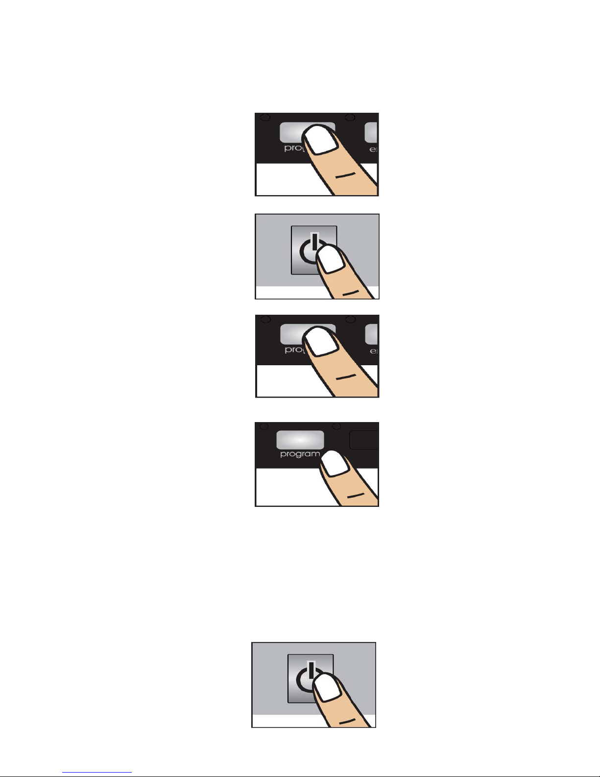
Fully-Integrated Models;
I
ND13 and IND21 models,
a) Press the Program selector button and keep it pressed down while your machine is not in
operation,
b) Meanwhile, energise the machine by pressing the On/Off button.
c) Keep Program selector button pressed until all indicators are on and off for the second
time.
d) After all the lights have flashed, release the Program selector button..
The machine shows the last error, then starts to sevice programme.
e) End of the programme the end lamb is on. If the machine comes to error position, the
lambs ,showed failure codes, are on and the machine shows the first failure code on service
programme.
f) Press on/off button to close the machine.
- 26 -
Page 27
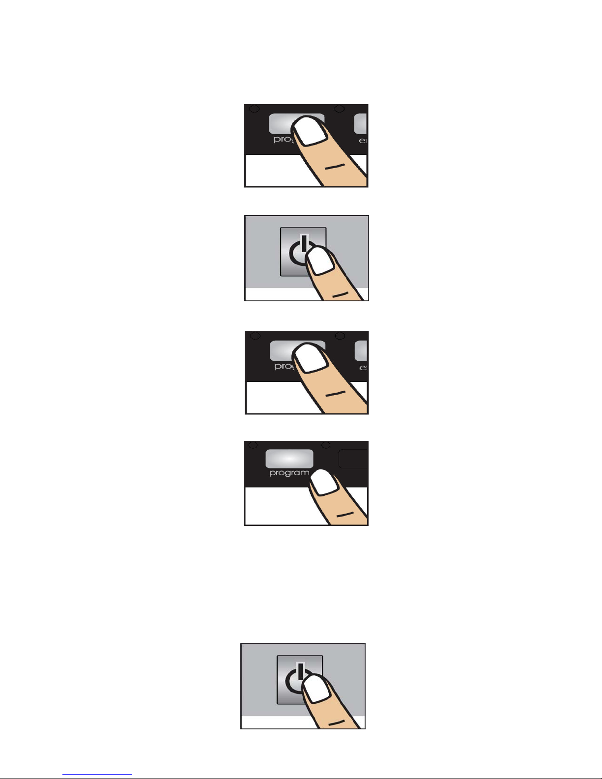
IND41 model,
a)
Press the Program selector button and keep it pressed down while your machine is not in
operation,
b) Meanwhile, energise the machine by pressing the On/Off button.
c) Keep Program selector button pressed until ‘’SP’’ appears on display.
d) After all the lights have flashed, release the Program selector button.
The machine shows the last error, then starts to sevice programme.
e) End of the service programme the end lamb is on. If the machine comes to error position,
the lambs ,showed failure codes, are on and the machine shows the first failure code on
service programme
f) Press on/off button to close the machine.
- 27 -
Page 28
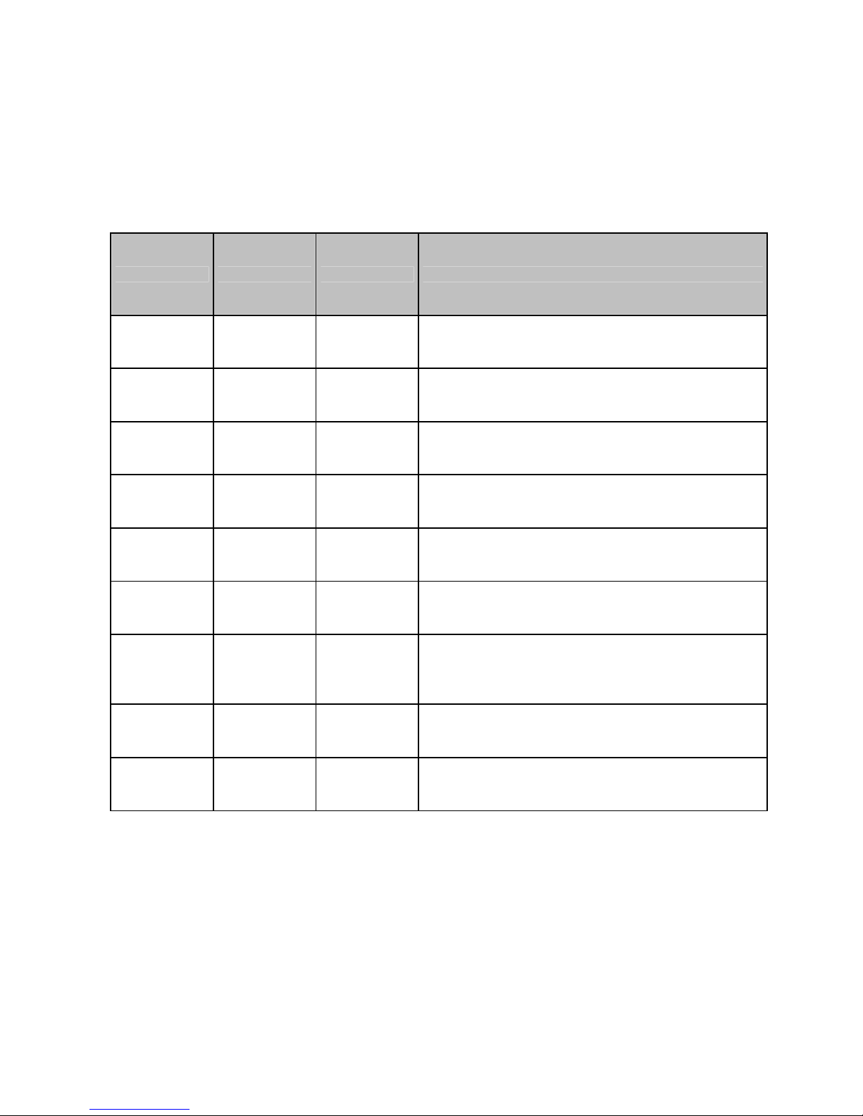
Auto test program algorithm steps:
Steps in program algorithm fallows each other automati
program ends and gives failure code. You can learn the error from the Service Failure Code.
Steps Process Time Control
cally. When there is a problem,
Show the last
0
1 Drain ~4 sec Drain pump is running
2 Fill (~3,5lt) ~1min 25 sec
3
4 Washing pump ~1 min 10sec Circulation pump – detergant dispenser
5
6 Regeneration ~1 min Regeneration valve
7 Drain ~ 20sec Drain Pump
failure occured
before
Turbidity
sensor
Wash pump +
Heating
~6 sec
~30 sec (For C4 models)
~5 min Heater Casing (pressure switch)- NTC- diverter positions
The machine shows the last error, before the sevice
programme starts
Water inlet valve and flowmeter is controlled.
(At 2,5lt circulation pump starts to run)
8
Note: The values declared above are the values obtained under laboratory conditions according to the relevant
standards. These values can change depending on conditions of product’s use and environment (network tension,
water input temperature and environment temperature)
End led
highlight
SERVICE FAILURE CODE
While your machine is in operation, gives feedback informations. The indicators are on and
off with different combinations or the failure code appaers on display, then you can identify
the possible problem by looking the fallowing failure code tables.
- 28 -
Page 29
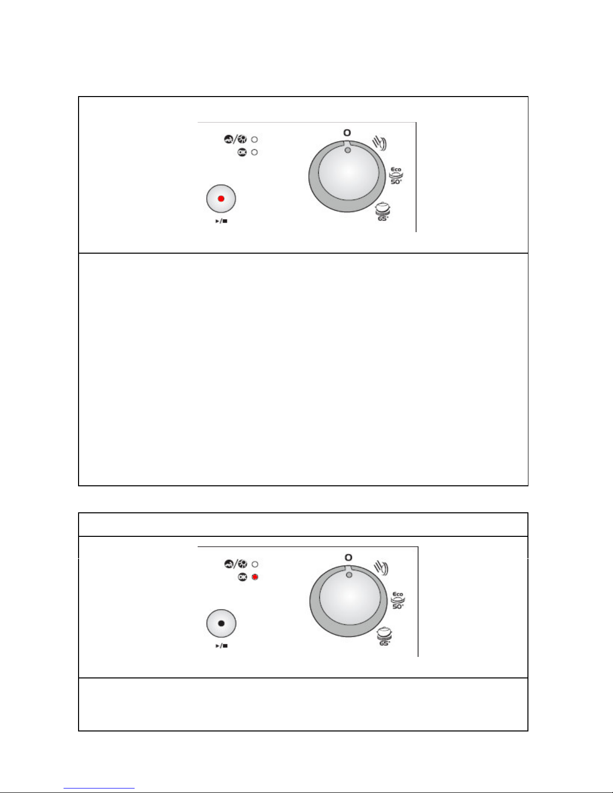
FREE-STANDING and SEMI-INTEGRATED
C
11,C12,C13 FAILURE CODES
1. Inadequate water supply
Possible problems:
1- Make sure the water input tap is totally open and that there is no water cut.
2- Close the water input tap, separate the water input hose from the tap and clean the
filter at the connection end of the hose.
3-Water inlet hose can be out of order.
4- Water inlet valve filter can be clogged.
5- Water inlet valve can be out of order.
6- There can be a problem with the cable connection of water inlet valve.
7- Floater switch can be out of order or have a problem with the cable connection.
8- Pressure switch of the heater casing group can have a mechanical or cable
connection problem.
9- Circulation pump can be out of order or have a problem with the cable connection.
2. Error of continuous water input
Possible problems:
1- Water inlet valve can be out of order or can not be closed.
2- Electronic card can be out of order.
- 29 -
Page 30
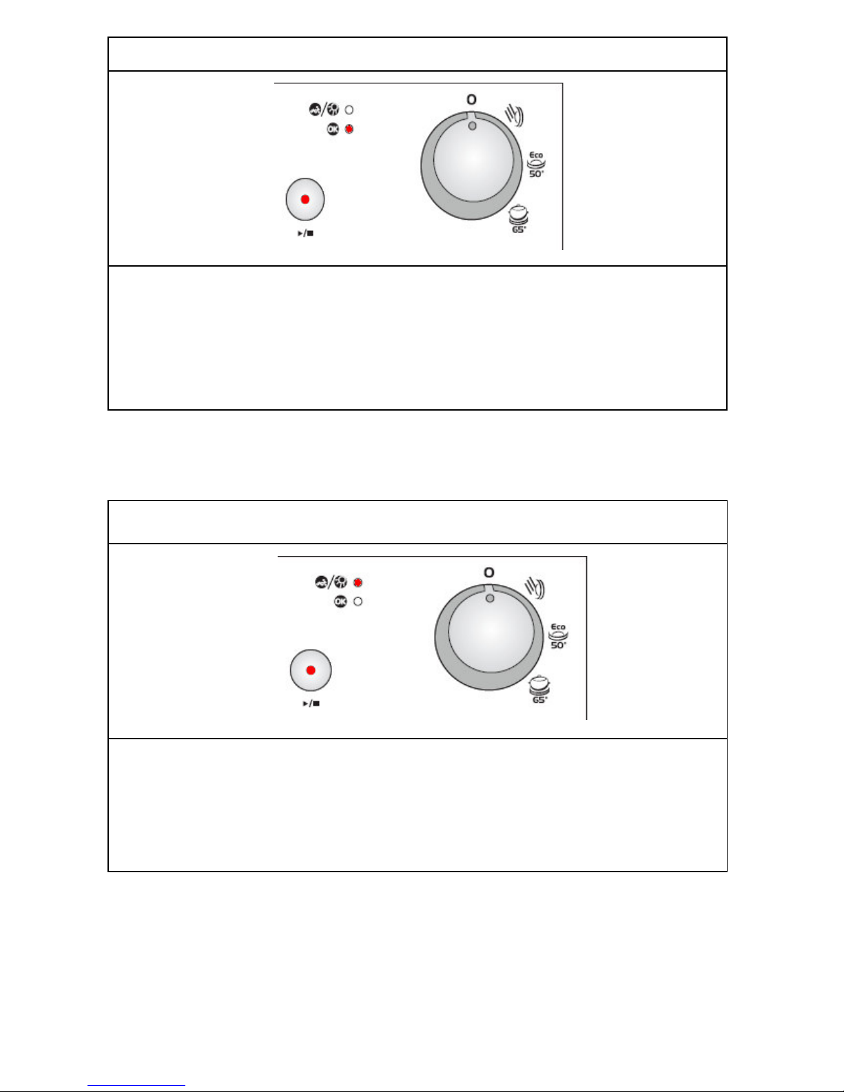
3. T
he waste water in the machine cannot be discharged
Possible problems:
1- Water outlet hose is clogged.
2-Water outlet hose position can be too high.
3-The drain pump can be out of order.
4- There can be a problem with cable connection of the drain pump.
5- Pressure switch of the heater casing group can have a mechanical or cable
connection problem.
4. Intended water temperature could not be reached - faulty heater and/or
heater sensor
Possible problems:
1-NTC can be out of order.
2- NTC cable connection can be faulty. NTC can be short or open circuit.
3- Thermal protection can be out of order.
4- Heater can be out of order or cable connection can be faulty.
- 30 -
Page 31
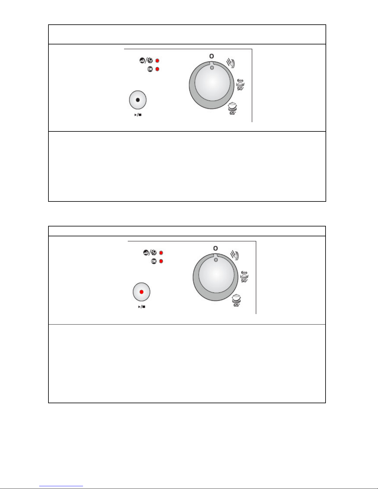
5.
Alarm is active against water overflow
Possible problems:
1- There can be a water leakage from the tub.
2- Floater switch can be out of order or have a problem with the cable connection.
3-Drain pump and pessure switch can be out of order at the same time.
4-Electronic card can be out of order.
6. Electronic card parameter faulty
Possible problems:
1- By the immediate and continuous voltage decreases software variants can not be
kept in the memory of electronic card.
2- The program contiues, when you restart it. You should warn the user about
controlling the network voltage.
- 31 -
Page 32
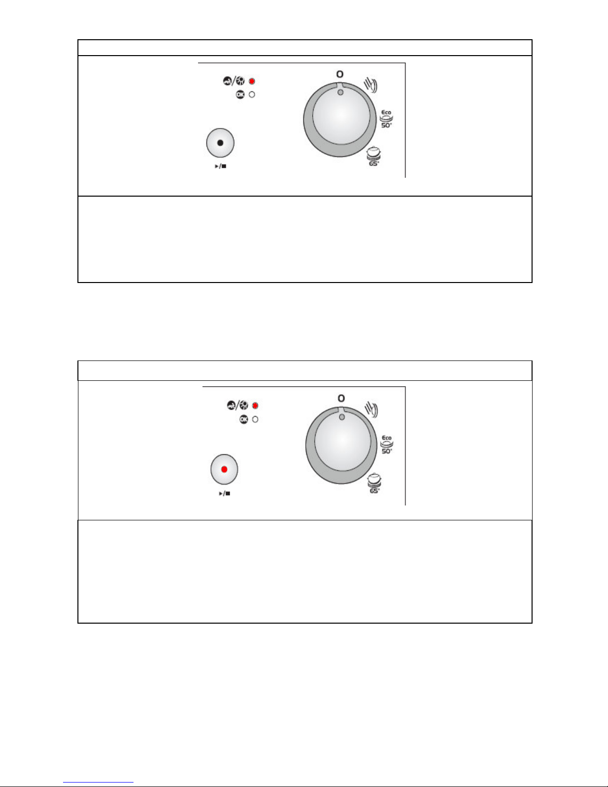
7.
Faulty Flowmeter
Possible problems:
1-Flowmeter can be out of order.
2- Cable connection of flowmeter can be faulty.
3- Electronic card can be out of order.
8. Door is open
Possible problems:
1-Door lock mechanism can be out of order.
2- There can be a problem with the cable connection of door lock.
3- Electronic card can be out of order.
- 32 -
Page 33
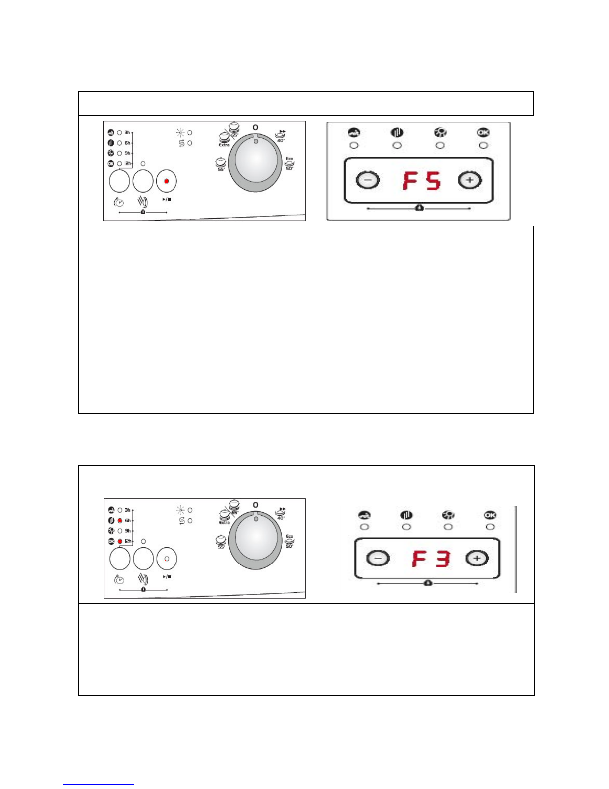
FREE-STANDING AND SEMI-INTEGRATED
C
21,C31,C41 FAILURE CODES
1. Inadequate water supply
Possible problems:
1- Make sure the water input tap is totally open and that there is no water cut.
2- Close the water input tap, separate the water input hose from the tap and clean the filter
at the connection end of the hose.
3-Water inlet hose can be out of order.
4- Water inlet valve filter can be clogged.
5- Water inlet valve can be out of order.
6- There can be a problem with the cable connection of water inlet valve.
7- Floater switch can be out of order or have a problem with the cable connection.
8- Pressure switch of the heater casing group can have a mechanical or cable connection
problem.
9- Circulation pump can be out of order or have a problem with the cable connection.
2. Error of continuous water input
Possible problems:
1- Water inlet valve can be out of order or can not be closed.
2- Electronic card can be out of order.
- 33 -
Page 34
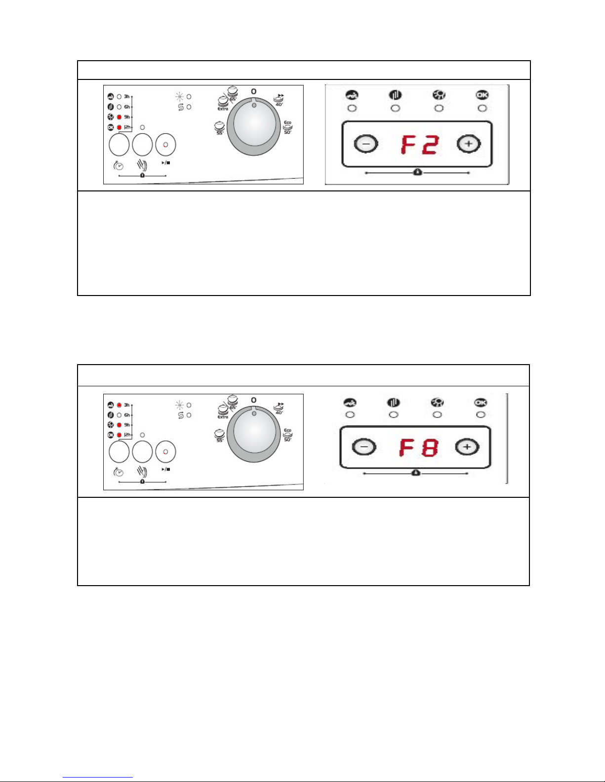
3
. The waste water in the machine cannot be discharged
Possible problems:
1- Water outlet hose is clogged.
2-Water outlet hose position can be too high.
3-The drain pump can be out of order.
4- There can be a problem with cable connection of the drain pump.
5- Pressure switch of the heater casing group can have a mechanical or cable connection
problem.
4. Heater Error: Inadequate heat
Possible problems:
1- Heater can be out of order.
2- There can be a problem with cable connection of the heater.
3- Thermal protection can be out of order.
4- Electronic card can be out of order.
- 34 -
Page 35
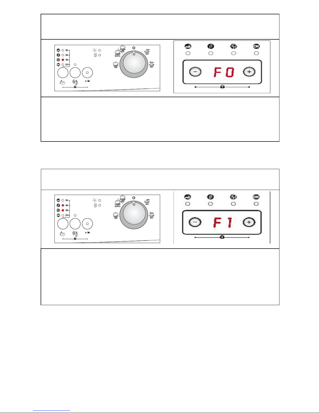
5
. Alarm is active against water overflow
Possible problems:
1- Floater switch can be out of order or have a problem with the cable connection.
2- Electronic card can be out of order.
6. Alarm is active against water leakage
Possible problems:
1- There can be a water leakage from the tub.
2- Floater switch can be out of order or have a problem with the cable connection.
3- Drain pump and pessure switch can be out of order at the same time.
4- Electronic card can be out of order.
- 35 -
Page 36
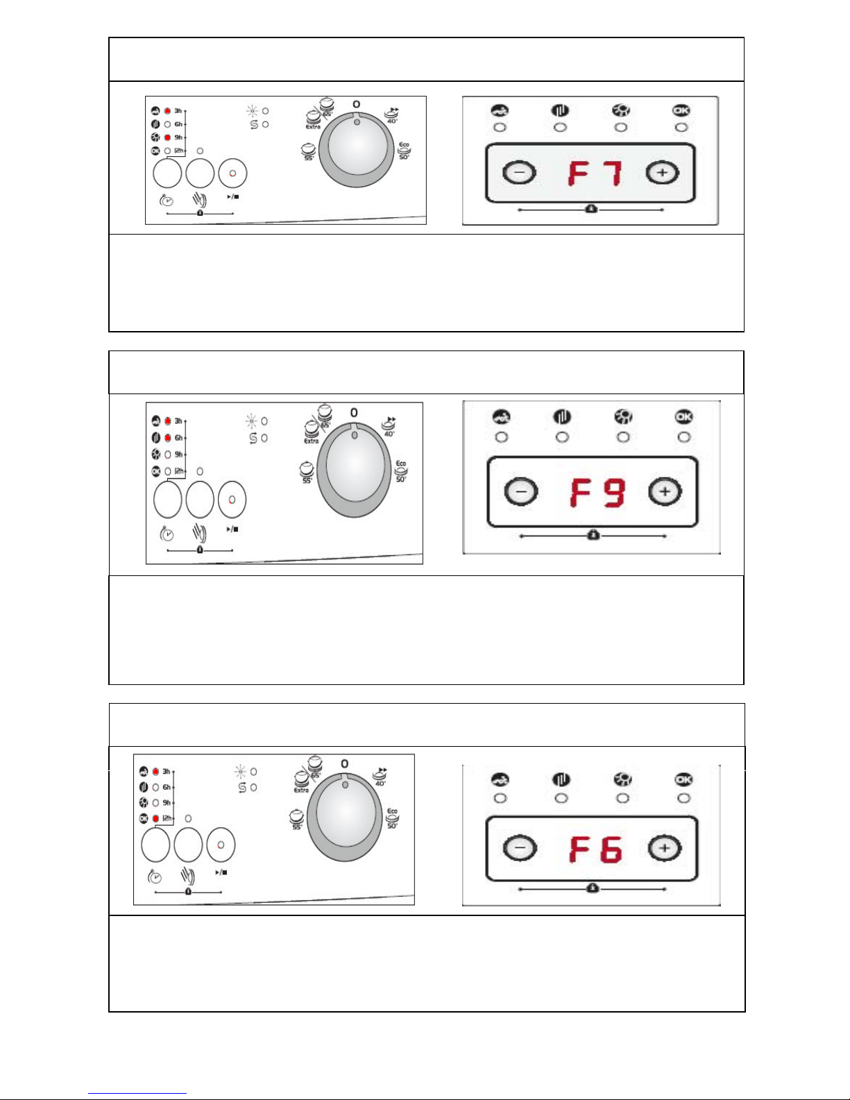
7.
Exceed heating problem (water inside the machine is too high)
Possible problems:
1- Water inside the machine is >77°C, NTC can be out of order.
2- Electronic card can be out of order.
8. Diverter position problem
Possible problems:
1- There can be a water leakage to diverter contacts and diverter electric contacts can
have open circuit
2- There can be a problem with cable connection of the diverter.
3- Electronic card can be out of order.
9. NTC faulty
Possible problems:
1- NTC can be out of order.
2- NTC cable connection can be faulty. NTC can be short or open circuit.
3- Electronic card can be out of order.
- 36 -
Page 37
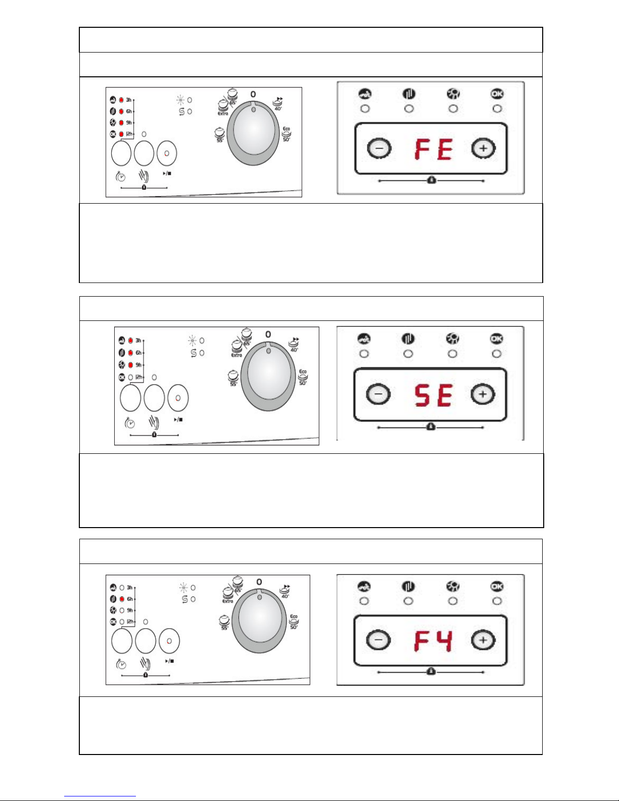
10. Electronic card parameter faulty
Possible problems:
1- By the immediate and continuous voltage decreases software variants can not be kept
in the memory of electronic card.
2- The program contiues, when you restart it. You should warn the user about controlling
the network voltage.
11. Electronic card water hardness faulty
Possible problems:
1- Water Hardness is not adjusted or Water Hardness adjustment can not be kept in the
elctronic card memory.
2- Water Hardness should be adjusted by controlling the supply water.
Possible problems:
1-Flowmeter can be out of order.
2- Cable connection of flowmeter can be faulty.
3- Electronic card can be out of order.
12. Faulty Flowmeter
- 37 -
Page 38
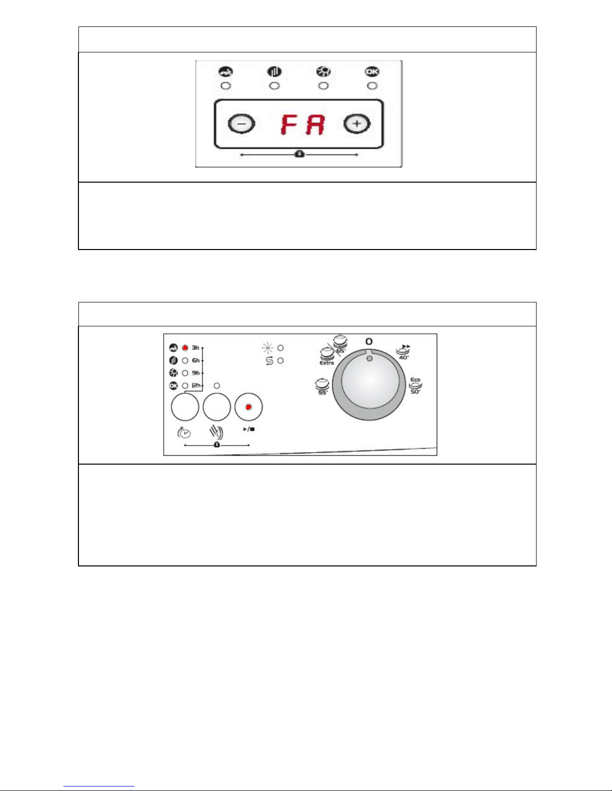
13. F
aulty turbidity sensor
Possible problems:
1- Turbidity sensor can be out of order.
2- There can be some soil around the turbidity sensor.
3- Electronic card can be out of order.
14. Door is open
Possible problems:
1-Door lock mechanism can be out of order.
2- There can be a problem with the cable connection of door lock.
3- Electronic card can be out of order.
- 38 -
Page 39
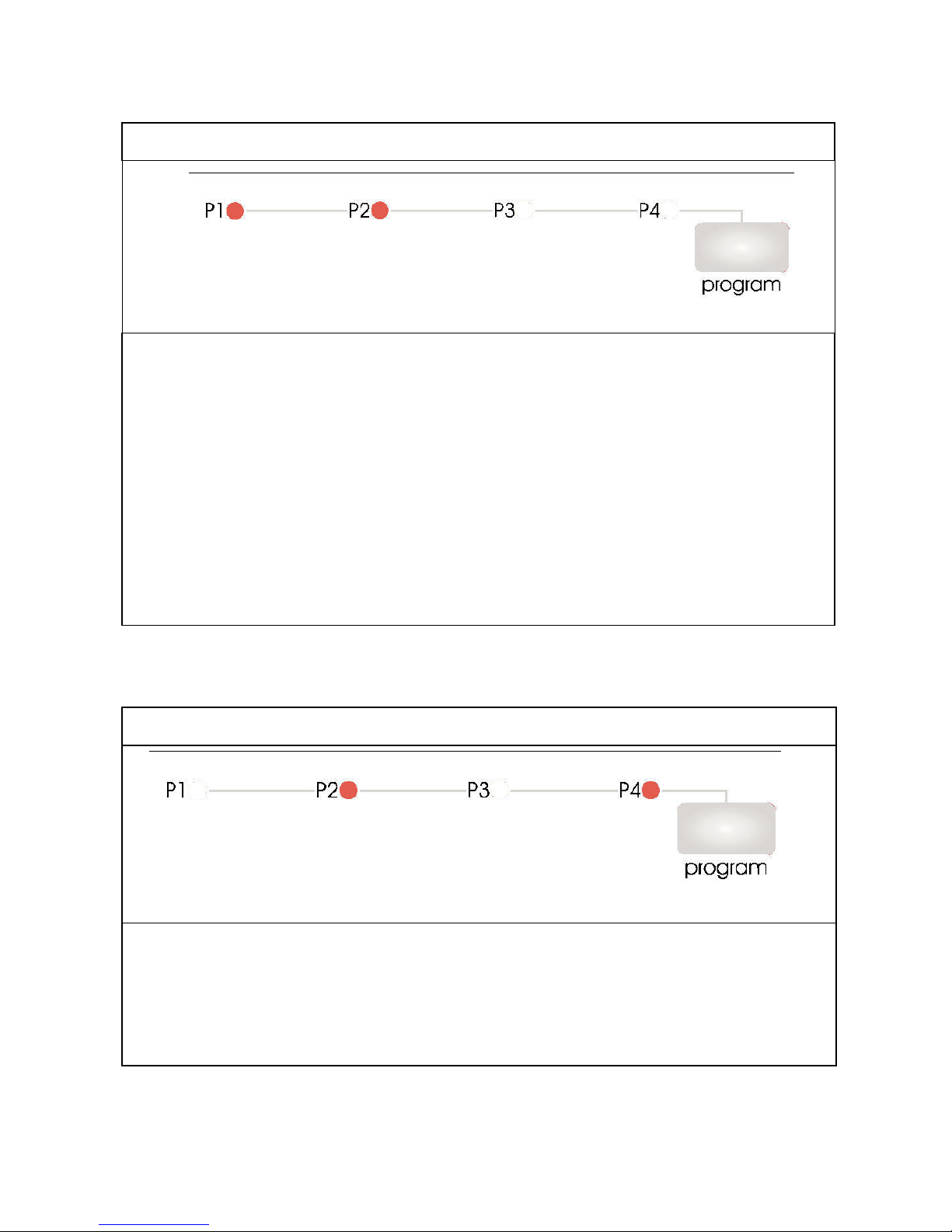
FULLY-INTEGRATED
C
13 FAILURE CODES
1. Inadequate water supply
Possible problems:
1- Make sure the water input tap is totally open and that there is no water cut.
2- Close the water input tap, separate the water input hose from the tap and clean the filter
at the connection end of the hose.
3-Water inlet hose can be out of order.
4- Water inlet valve filter can be clogged.
5- Water inlet valve can be out of order.
6- There can be a problem with the cable connection of water inlet valve.
7- Floater switch can be out of order or have a problem with the cable connection.
8- Pressure switch of the heater casing group can have a mechanical or cable connection
problem.
9- Circulation pump can be out of order or have a problem with the cable connection.
2. Error of continuous water input
Possible problems:
1- Water inlet valve can be out of order or can not be closed.
2- Electronic card can be out of order.
- 39 -
Page 40
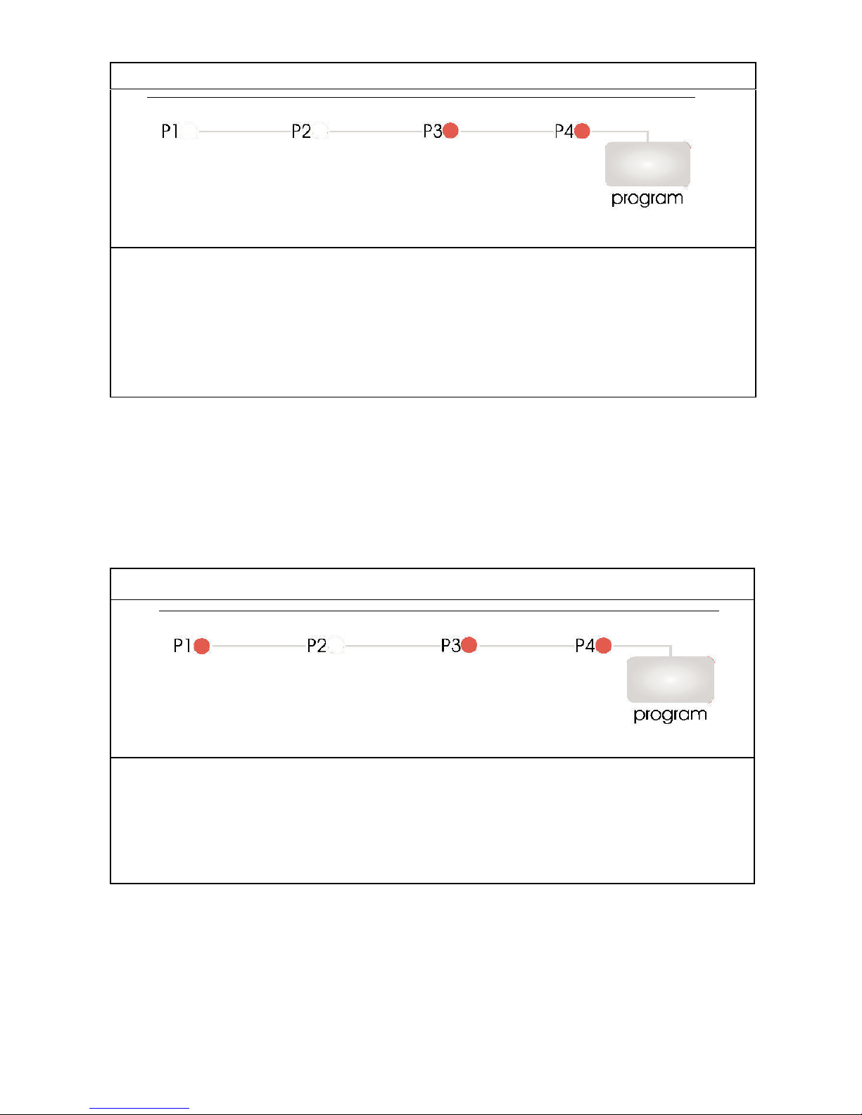
3
. The waste water in the machine cannot be discharged
Possible problems:
1- Water outlet hose is clogged.
2-Water outlet hose position can be too high.
3-The drain pump can be out of order.
4- There can be a problem with cable connection of the drain pump.
5- Pressure switch of the heater casing group can have a mechanical or cable connection
problem.
4. Heater Error: Inadequate heat
Possible problems:
1- Heater can be out of order.
2- There can be a problem with cable connection of the heater.
3- Thermal protection can be out of order.
4- Electronic card can be out of order.
- 40 -
Page 41
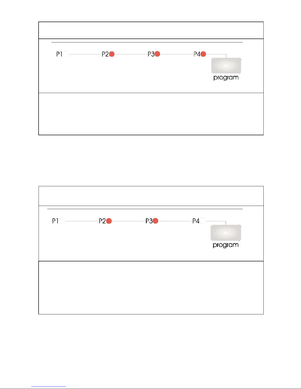
5
. Alarm is active against water overflow
Possible problems:
1- Floater switch can be out of order or have a problem with the cable connection.
2- Electronic card can be out of order.
6. Alarm is active against water leakage
Possible problems:
1- There can be a water leakage from the tub.
2- Floater switch can be out of order or have a problem with the cable connection.
3- Drain pump and pessure switch can be out of order at the same time.
4- Electronic card can be out of order.
- 41 -
Page 42
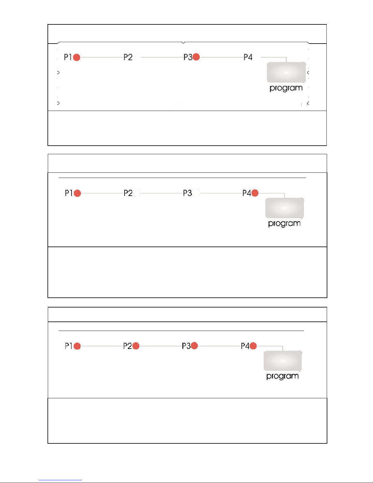
7.
Exceed heating problem (temp. of water inside the machine is too high)
Possible problems:
1- Water inside the machine is >77°C, NTC can be out of order.
2- Electronic card can be out of order.
8. NTC faulty
Possible problems:
1- NTC can be out of order.
2- NTC cable connection can be faulty. NTC can be short or open circuit.
3- Electronic card can be out of order.
9. Electronic card parameter faulty
Possible problems:
1- By the immediate and continuous voltage decreases software variants can not be kept
in the memory of electronic card.
2- The program contiues, when you restart it. You should warn the user about controlling
the network voltage.
- 42 -
Page 43
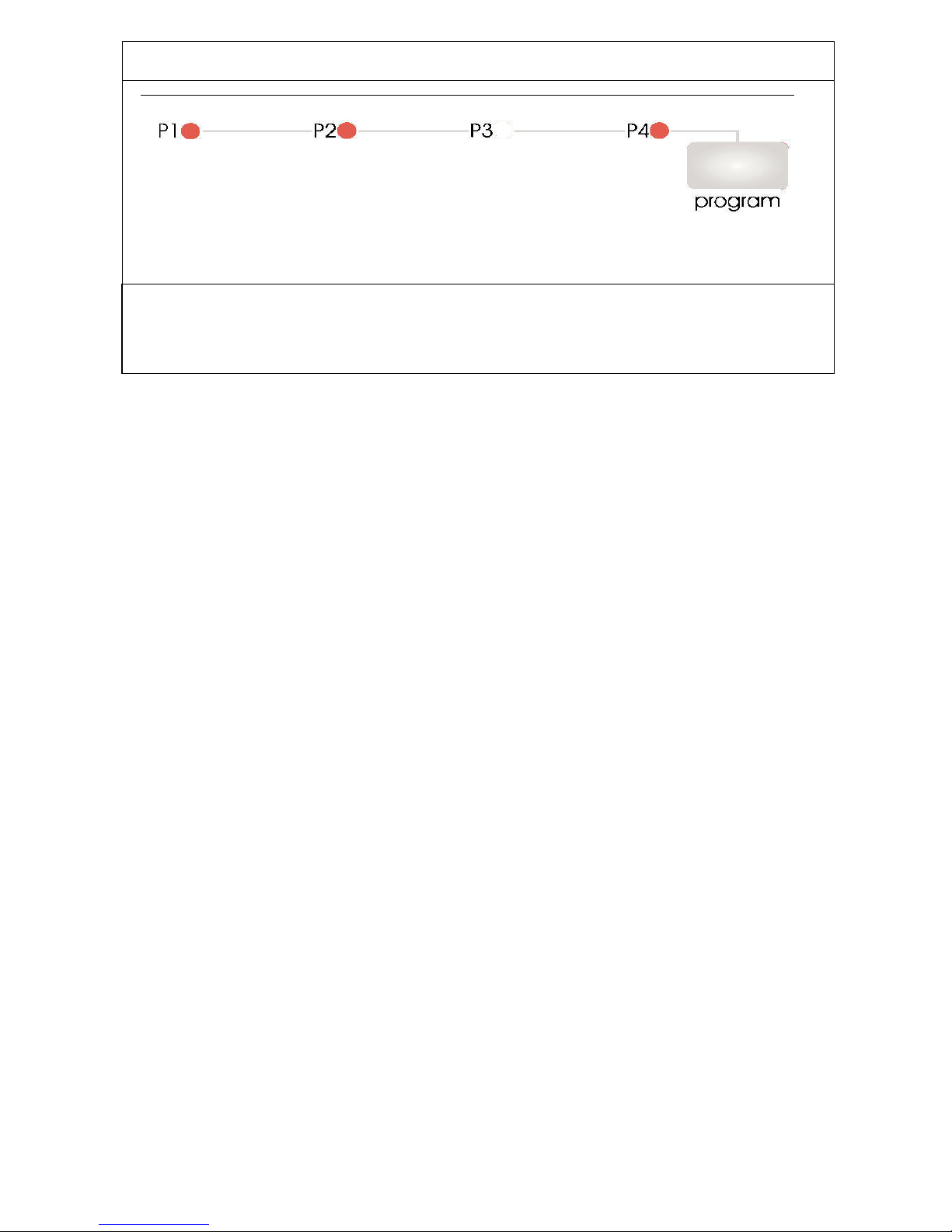
10.
Faulty Flowmeter
Possible problems:
1-Flowmeter can be out of order.
2- Cable connection of flowmeter can be faulty.
3- Electronic card can be out of order.
- 43 -
Page 44
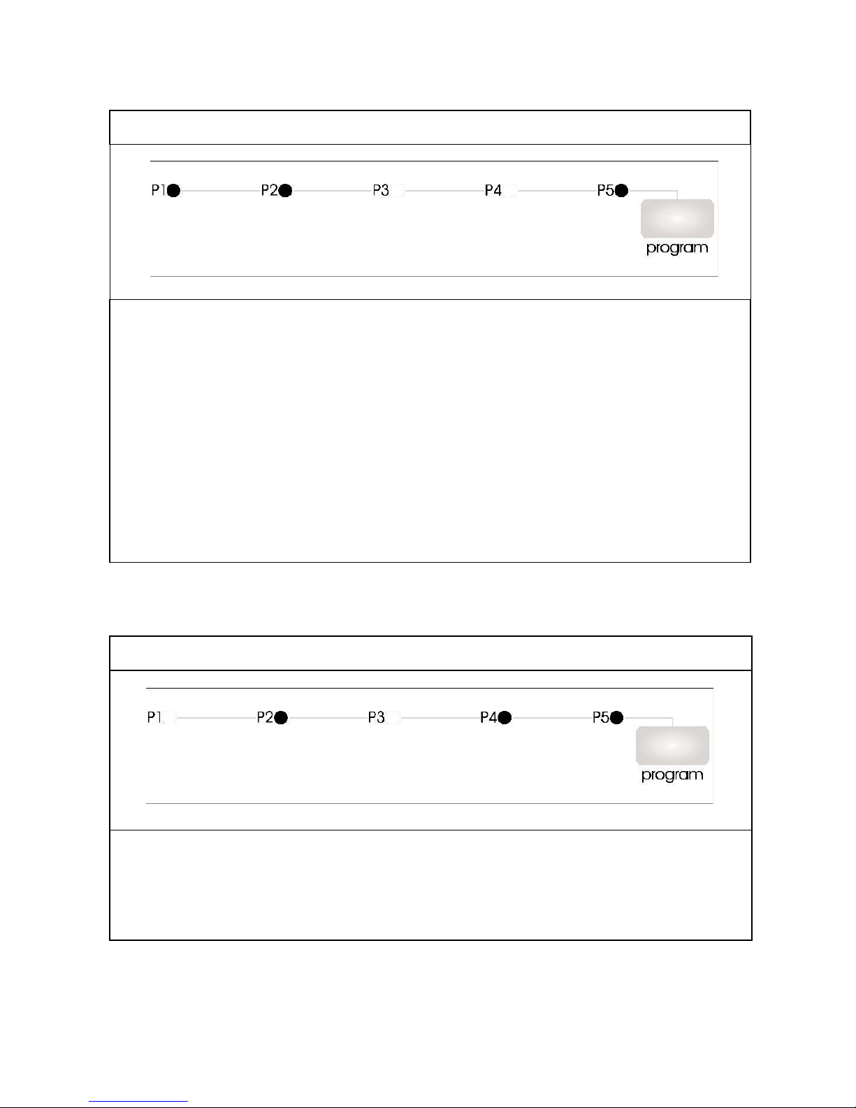
FULLY-INTEGRATED
C
21 FAILURE CODES
1. Inadequate water supply
Possible problems:
1- Make sure the water input tap is totally open and that there is no water cut.
2- Close the water input tap, separate the water input hose from the tap and clean the filter
at the connection end of the hose.
3-Water inlet hose can be out of order.
4- Water inlet valve filter can be clogged.
5- Water inlet valve can be out of order.
6- There can be a problem with the cable connection of water inlet valve.
7- Floater switch can be out of order or have a problem with the cable connection.
8- Pressure switch of the heater casing group can have a mechanical or cable connection
problem.
9- Circulation pump can be out of order or have a problem with the cable connection.
2. Error of continuous water input
Possible problems:
1- Water inlet valve can be out of order or can not be closed.
2- Electronic card can be out of order.
- 44 -
Page 45
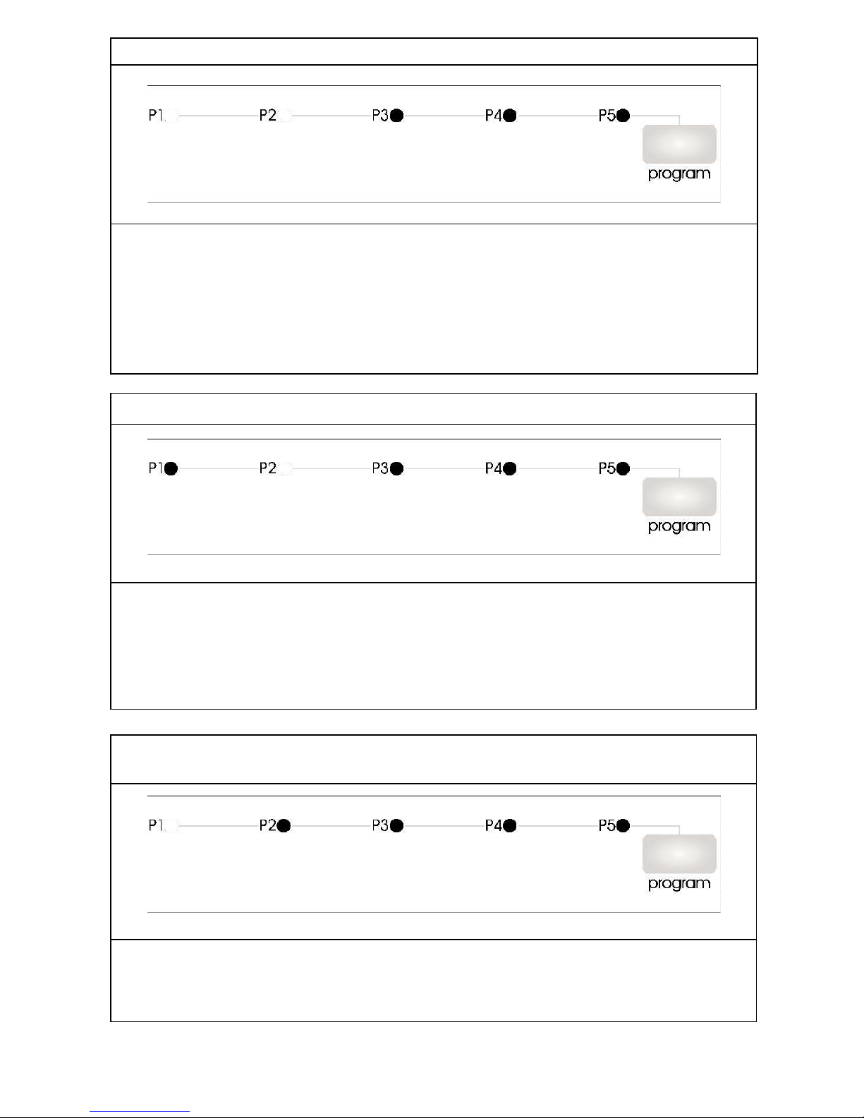
3. T
he waste water in the machine cannot be discharged
Possible problems:
1- Water outlet hose is clogged.
2-Water outlet hose position can be too high.
3-The drain pump can be out of order.
4- There can be a problem with cable connection of the drain pump.
5- Pressure switch of the heater casing group can have a mechanical or cable connection
problem
4. Heater Error: Inadequate heat
Possible problems:
1- Heater can be out of order.
2- There can be a problem with cable connection of the heater.
3- Thermal protection can be out of order.
4- Electronic card can be out of order.
5. Alarm is active against water overflow
Possible problems:
1- Floater switch can be out of order or have a problem with the cable connection.
2- Electronic card can be out of order.
- 45 -
Page 46
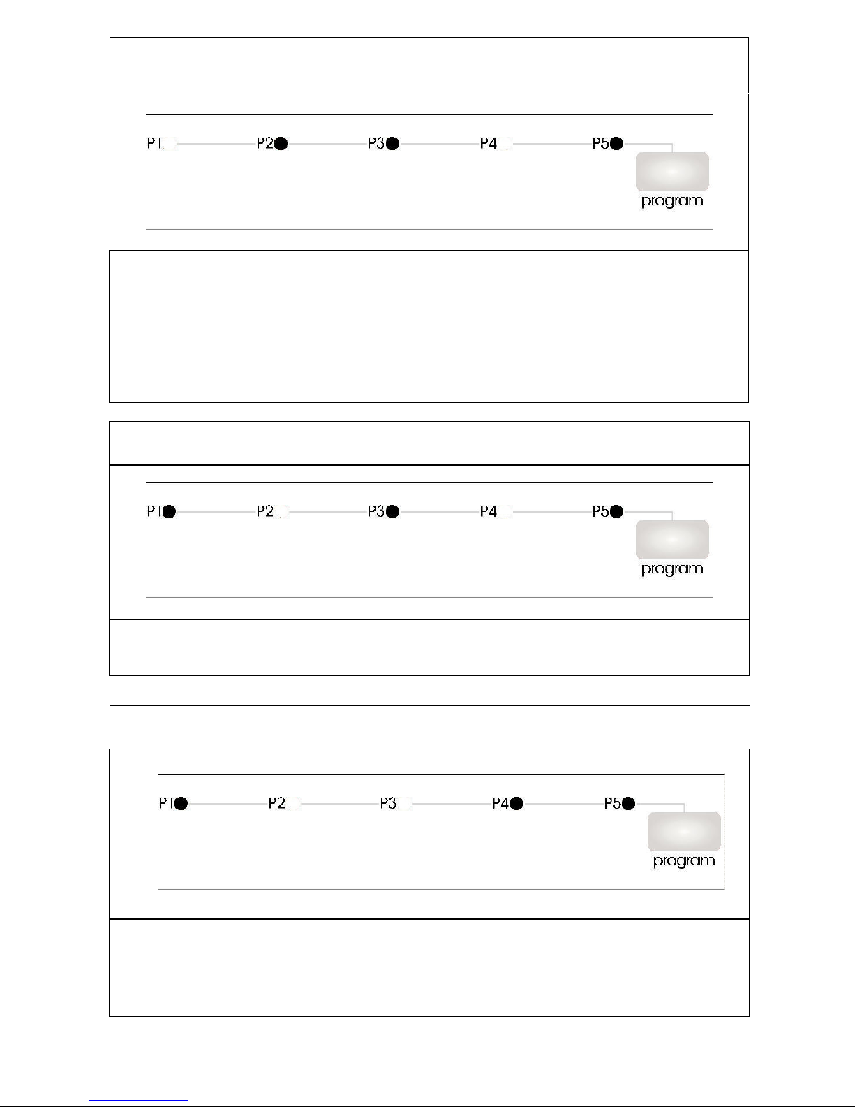
6.
Alarm is active against water leakage
Possible problems:
1- There can be a water leakage from the tub.
2- Floater switch can be out of order or have a problem with the cable connection.
3- Drain pump and pessure switch can be out of order at the same time.
4- Electronic card can be out of order.
7. Exceed heating problem (temp. of water inside the machine is too high)
Possible problems:
1- Water inside the machine is >77°C, NTC can be out of order.
2- Electronic card can be out of order.
Possible problems:
1- NTC can be out of order.
2- NTC cable connection can be faulty. NTC can be short or open circuit.
3- Electronic card can be out of order.
8. NTC faulty
- 46 -
Page 47
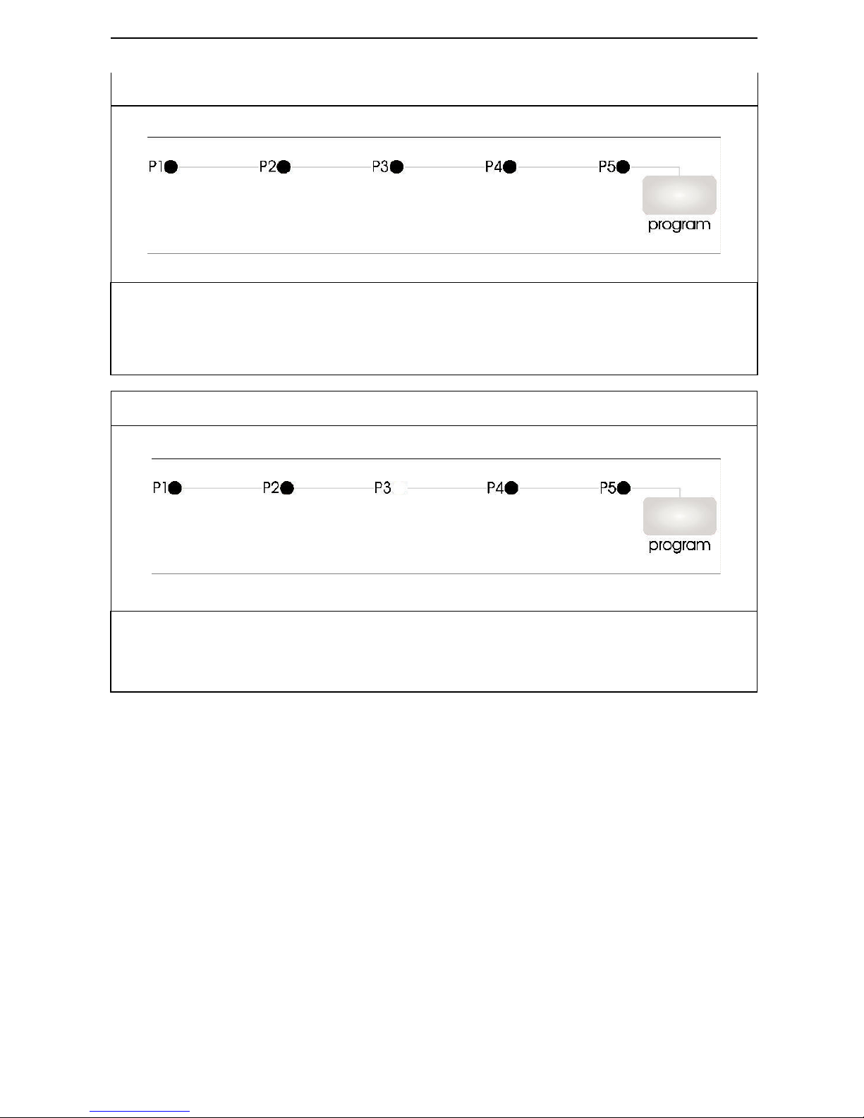
9. Electronic card parameter faulty
Possible problems:
1- By the immediate and continuous voltage decreases software variants can not be kept
in the memory of electronic card.
2- The program contiues, when you restart it. You should warn the user about controlling
the network voltage.
10. Faulty Flowmeter
Possible problems:
1-Flowmeter can be out of order.
2- Cable connection of flowmeter can be faulty.
3- Electronic card can be out of order.
- 47 -
Page 48
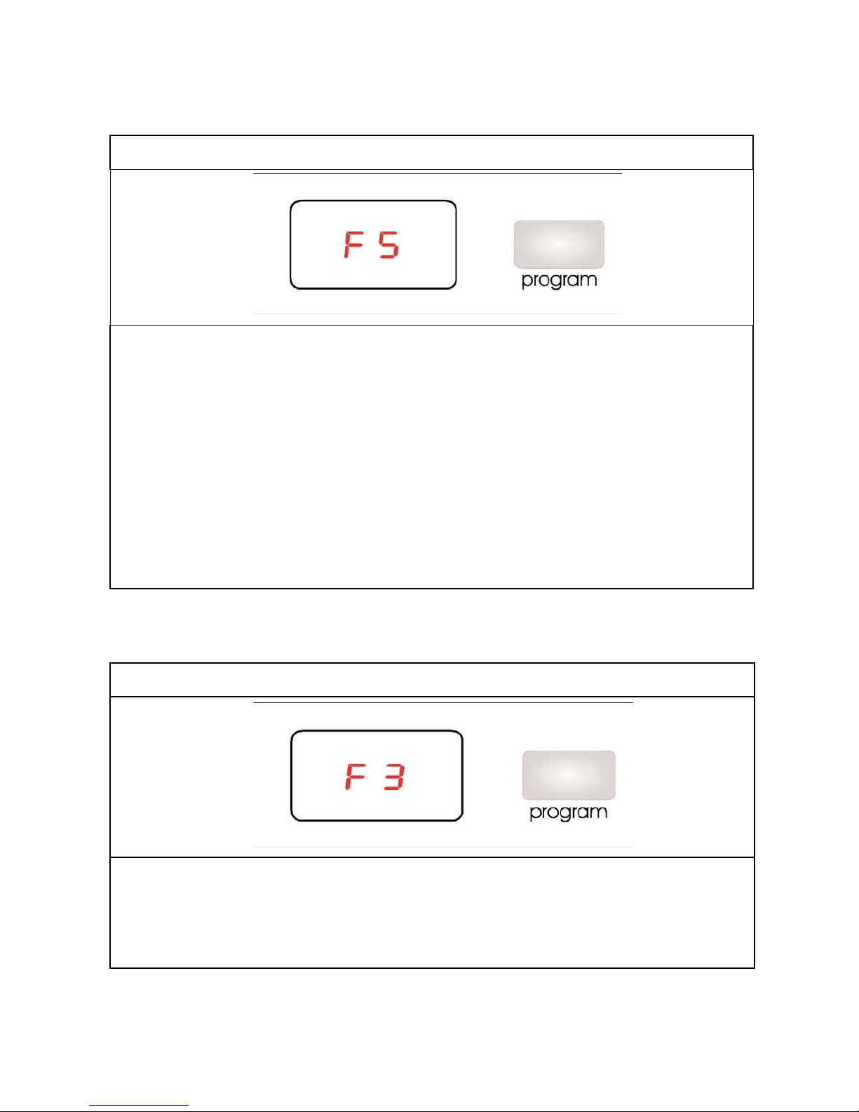
F
ULLY-INTEGRATED
C41 FAILURE CODES
1. Inadequate water supply
Possible problems:
1- Make sure the water input tap is totally open and that there is no water cut.
2- Close the water input tap, separate the water input hose from the tap and clean the filter
at the connection end of the hose.
3-Water inlet hose can be out of order.
4- Water inlet valve filter can be clogged.
5- Water inlet valve can be out of order.
6- There can be a problem with the cable connection of water inlet valve.
7- Floater switch can be out of order or have a problem with the cable connection.
8- Pressure switch of the heater casing group can have a mechanical or cable connection
problem.
9- Circulation pump can be out of order or have a problem with the cable connection.
2. Error of continuous water input
Possible problems:
1- Water inlet valve can be out of order or can not be closed.
2- Electronic card can be out of order.
- 48 -
Page 49
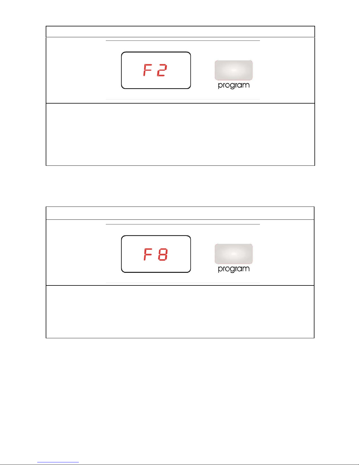
3
. The waste water in the machine cannot be discharged
Possible problems:
1- Water outlet hose is clogged.
2-Water outlet hose position can be too high.
3-The drain pump can be out of order.
4- There can be a problem with cable connection of the drain pump.
5- Pressure switch of the heater casing group can have a mechanical or cable connection
problem
4. Heater Error: Inadequate heat
Possible problems:
1- Heater can be out of order.
2- There can be a problem with cable connection of the heater.
3- Thermal protection can be out of order.
4- Electronic card can be out of order.
- 49 -
Page 50
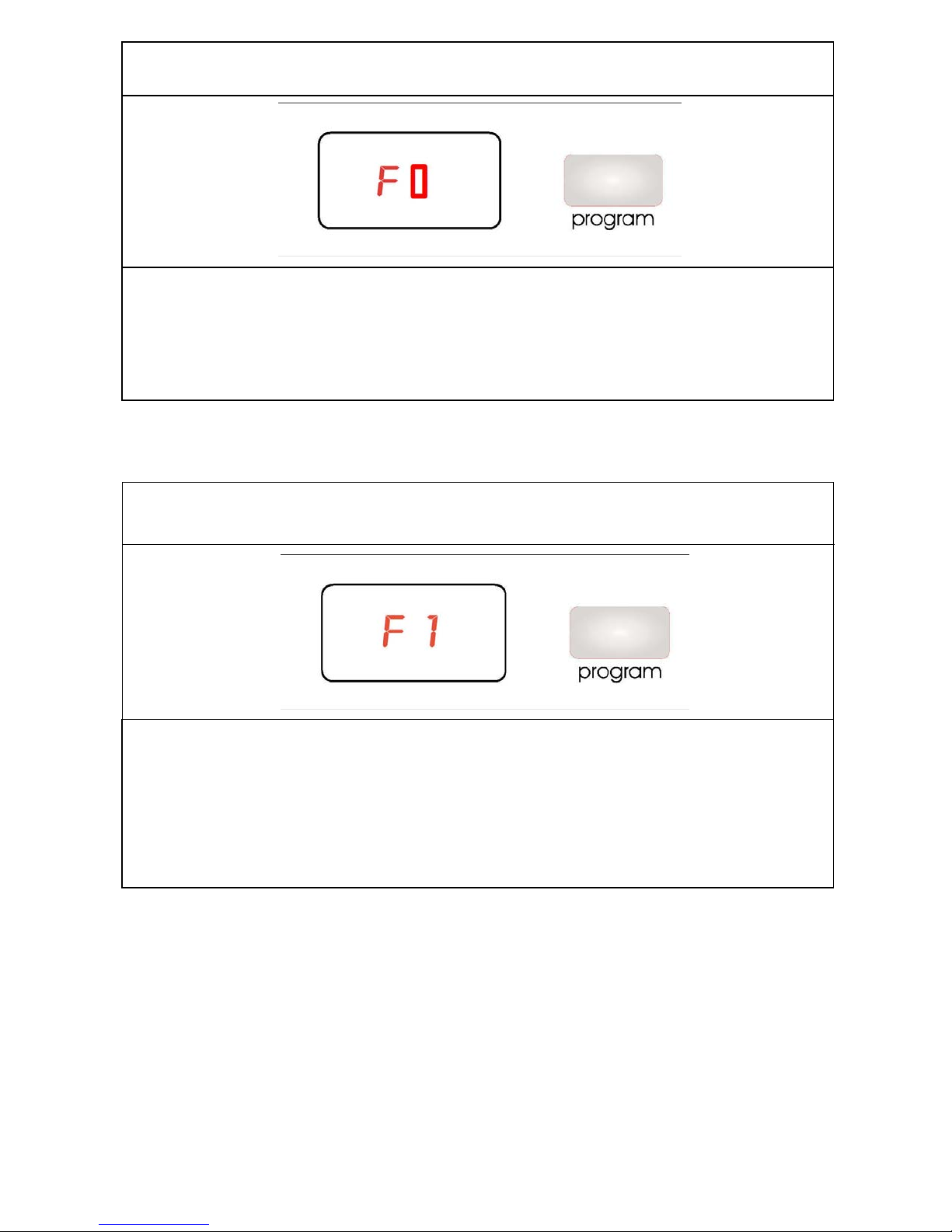
5. Alarm is active against water overflow
Possible problems:
1- Floater switch can be out of order or have a problem with the cable connection.
2- Electronic card can be out of order.
6. Alarm is active against water leakage
Possible problems:
1- There can be a water leakage from the tub.
2- Floater switch can be out of order or have a problem with the cable connection.
3- Drain pump and pessure switch can be out of order at the same time.
4- Electronic card can be out of order.
- 50 -
Page 51
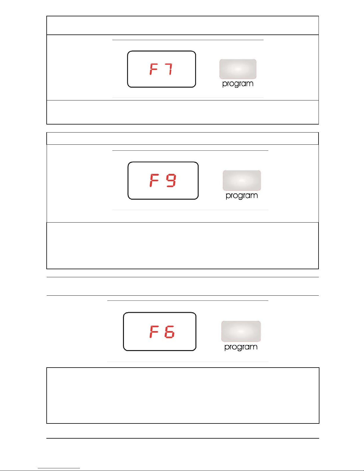
7.
Exceed heating problem (temp. of water inside the machine is too high)
Possible problems:
1- Water inside the machine is >77°C, NTC can be out of order.
2- Electronic card can be out of order.
8. Diverter position problem
Possible problems:
1- There can be a water leakage to diverter contacts and diverter electric contacts can
have open circuit
2- There can be a problem with cable connection of the diverter.
3- Electronic card can be out of order.
9. NTC faulty
Possible problems:
1- NTC can be out of order.
2- NTC cable connection can be faulty. NTC can be short or open circuit.
3- Electronic card can be out of order.
- 51 -
Page 52
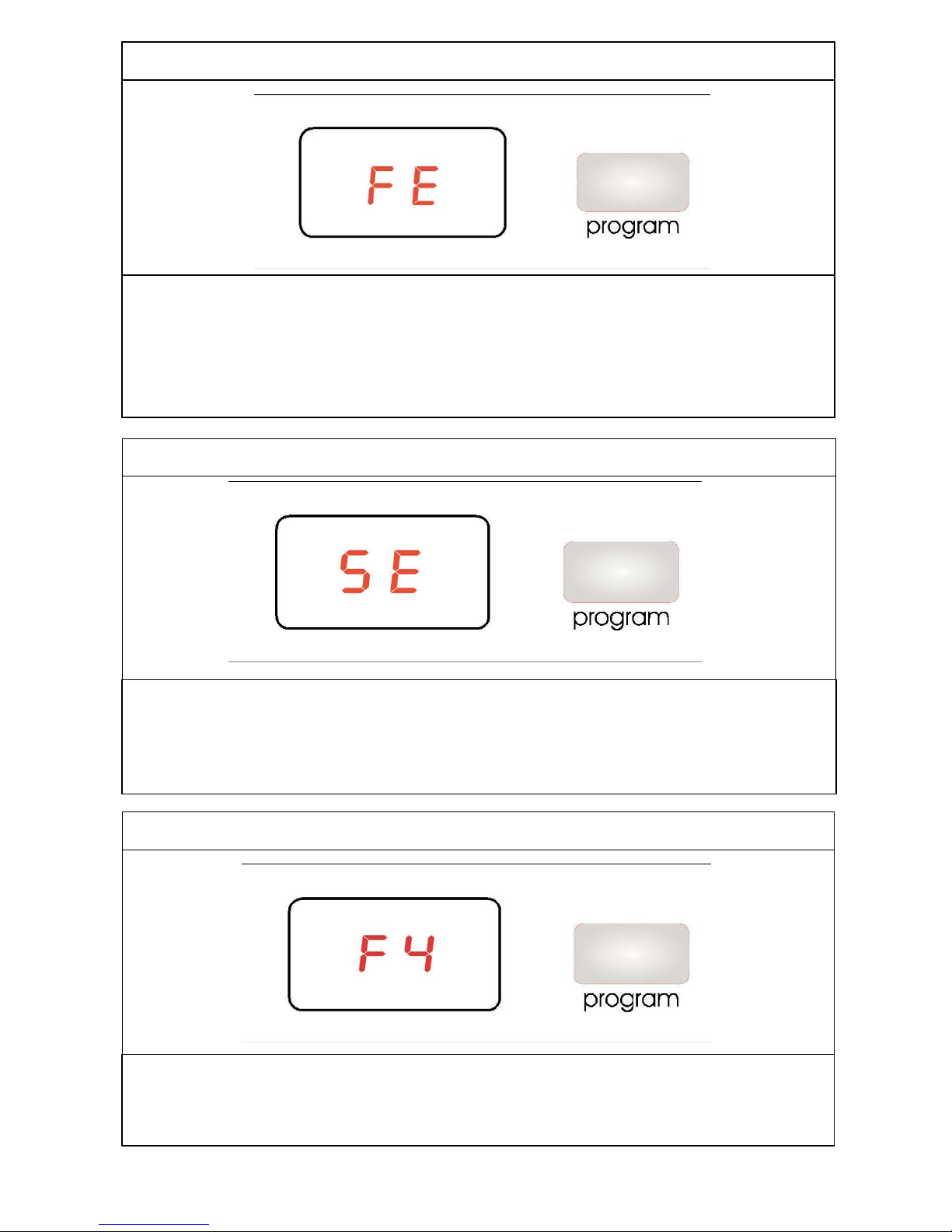
10.
Electronic card parameter faulty
Possible problems:
1- By the immediate and continuous voltage decreases software variants can not be kept
in the memory of electronic card.
2- The program contiues, when you restart it. You should warn the user about controlling
the network voltage.
11. Electronic card water hardness faulty
Possible problems:
1- Water Hardness is not adjusted or Water Hardness adjustment can not be kept in the
elctronic card memory.
2- Water Hardness should be adjusted by controlling the supply water.
Possible problems:
1-Flowmeter can be out of order.
2- Cable connection of flowmeter can be faulty.
3- Electronic card can be out of order.
12. Faulty Flowmeter
- 52 -
Page 53
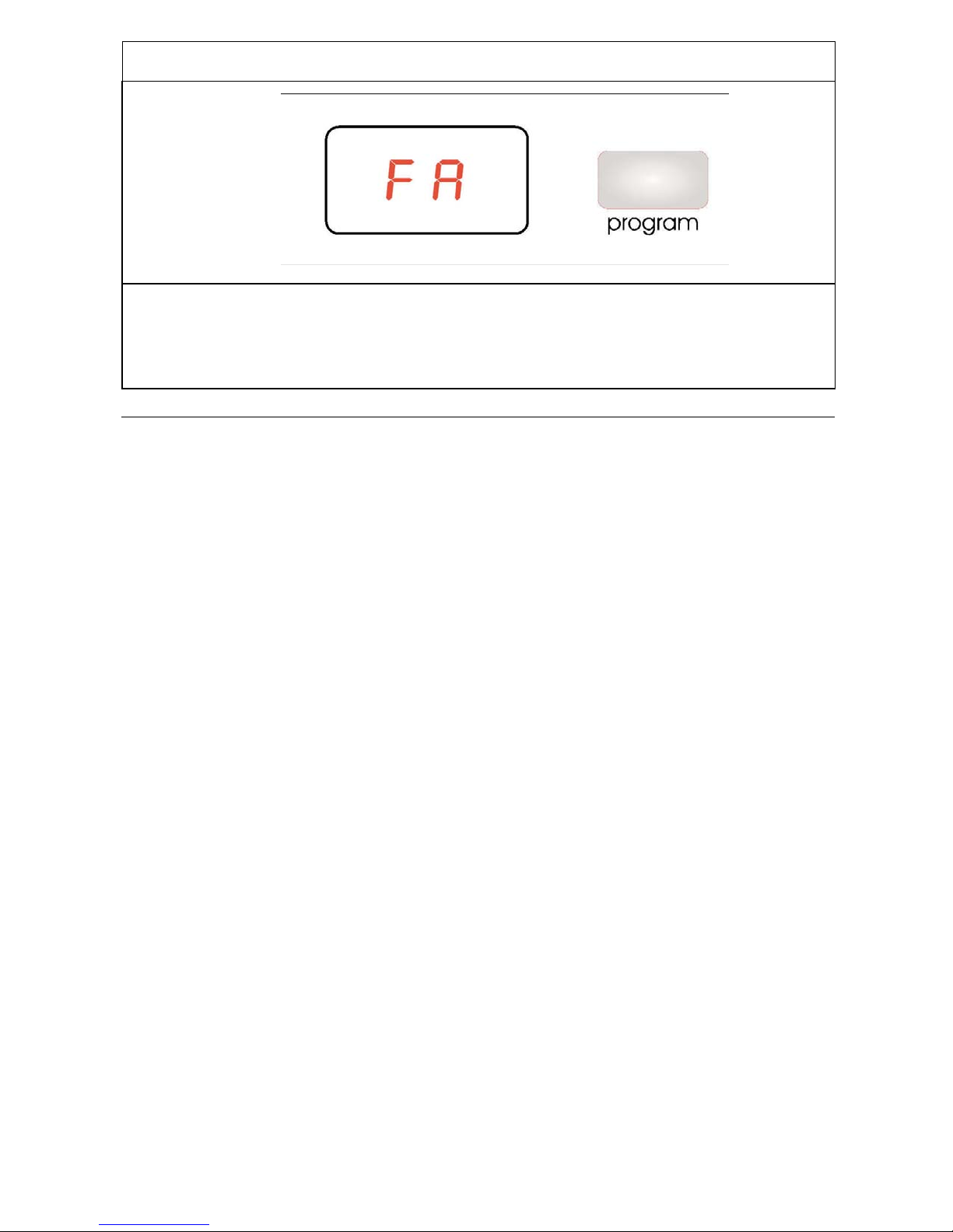
13. F
aulty turbidity sensor
Possible problems:
1- Turbidity sensor can be out of order.
2- There can be some soil around the turbidity sensor.
3- Electronic card can be out of order.
- 53 -
Page 54
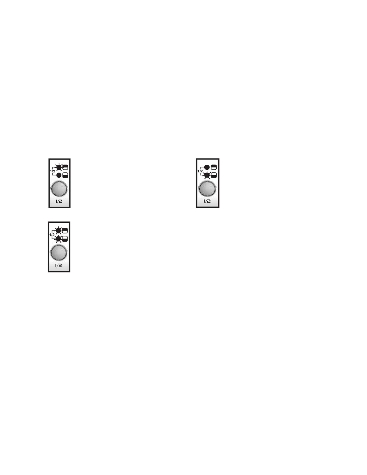
NECASSARY INFORMATION HAVE TO BE GIVEN
In ½ option, when
only upper
In ½ option, when only lower
When both lamps are
flashed
,
this
TO USERS WHILE INSTALLATING THE
DISHWASHER
Customers should be informed about following items.
• Give general information to user about the product.
• General information about washing programmes and suggest to the customer using
suitable program according to the dirtiness level.
• Give information about additional functions.
• Give information to the customer about starting the machine, following the program,
resetting the program and changing the program.
• Give information about activate and inactivate the child lock. Customers should be
informed about the child lock will not be inactivate automatically at the end of the
programme.
• Models haved ½ half load option;
lamp is flashed, only upper
spray will be in operation.
function is half load function. If the
customers have little amount of dishes,
they should use this function.
When both lamps are not flashed, it means the machine will continue normal
operation. When the lamps are not flashing , does not mean spray arms are not
rotating.
• The customers should be informed about looking at instruction manual at first, when they
face to failure.
• After installing the machine to a suitable place, run it unloaded for the first time.
This should be recommended to the customers that the
the instruction manual carefully when there is a possible repair.
lamp is flashed, only lower
spray will be on operation
y should search
- 54 -
Page 55
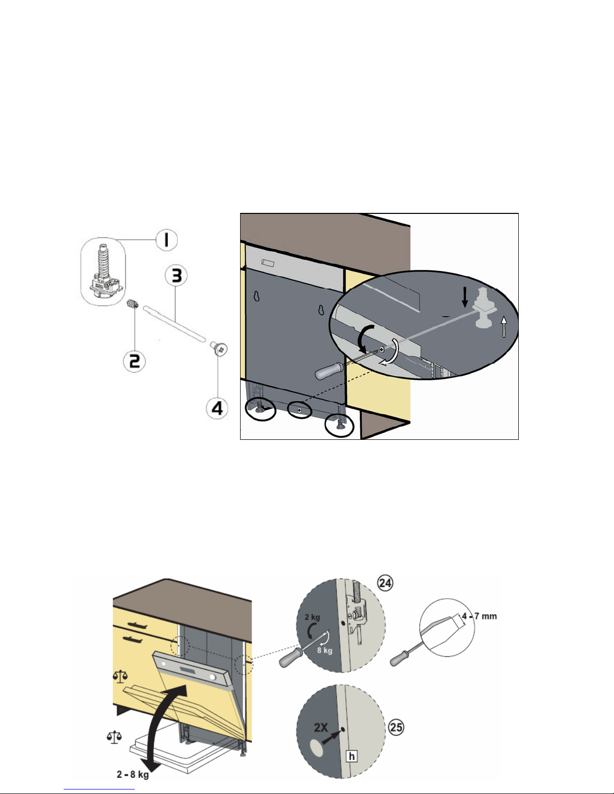
Semı-Integrated and Fully-Integrated Models
S
emi-Integrated and Fully-Integrated models have different pieces from free-standing
models;
• Built in adjustment mechanism
• Built in hinge spring adjustment mechanism
Built in feet adjustment mechanism,
You can easily adjust the machine backward feet through
Built in adjustment mechanism consists 4 main parts.
built in adjustment mechanism.
Built in adjustment mechanism
•
• Built in warm gear
• Built in height mechanism axle
• Built in adjustment mec. front cover
Built in hinge spring adjustment mechanism
Adjust the machine door by using screwdriver as you have seen in the picture.
- 55 -
Page 56
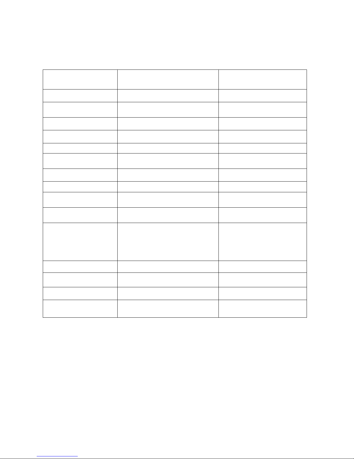
REPAIR TECHNIQUES
C
OMPONENTS AND RESISTANCE VALUES
COMPONENTS R
ON / OFF BUTTON
DOOR SWITCH (KAPI
KİLİDİ)
PRESSURE SWITCH
DRAIN PUMP
WATER INLET VALVE
REGENERATION
VALVE
SALT SENSOR
HEATER
DETERGENT
DISPENSER
CIRCULATION PUMP
SET NTC SENSOR
FAN MOTOR
EAL VALUES NOTES
0 Ω on component
CN2.9 – CN2.2 0 Ω Door is close
CN2.10 – CN2.2 0 Ω
∞ Ω
CN2.2 – CN2.4 143 Ω % ± 7
CN2.6 – CN 2.9 3750 Ω ± %10 (20Cº)
CN2.10 – CN2.7 4130 Ω ± %10(25 Cº)
CN5.1 – CN5.2 0 Ω NO SALT
∞ Ω THERE IS SALT
26.19±15 Ω
1660 Ω ± %10 (25 C º)
CN2.3 – CN2.9 95 ±%7 Ω
126 ±% 7 Ω
CN 3.2 25°- 5000Ω
CN 3.1 35°- 3300Ω %±5.5
55°- 1520Ω %±6.5
63°- 1174Ω %±7.5
80°- 670Ω %±8.0
90°- 488Ω %±8.5
CN 6.2 – CN 2.9 238.6 ± % 5
%±5.0
ON/OFF button is pressed
FULL FILL WATER
NO WATER
MEASURE JUST ON THE ELECTRONIC
CARD
MEASURE JUST ON THE COMPONENT
MEASURE JUST ON THE COMPONENT
Primary winding
Secondary winding (FROM THE
COMPONENT)
DIVERTER
RINSE AID SENSOR
FLOATER
(MICROSWITCH )
CN 6.1 – CN 2.9 6840 ± % 5
CN 5.3 – CN5.2 0 Ω
∞ Ω
CN2.1 – CN 2.5 0 Ω
CN2.1 – CN 2.4 ∞ Ω
RINSE AID OFF
RINSE AID ON
MICROSWİTICH IS INACTİVE (NO WATER)
MİKROSWITCH IS ACTIVE (THERE İS
WATER )
MEASURING THE COMPONENTS FROM THE
ELECTRONICAL CARD
You might measure the components either connentors of el
component.
Measuring from the connectors of electronic card gives definite results to define the repair. If
you know the specialities and values of tester, you can easily determine the repair.
- 56 -
ectronic card or directly on the
Page 57
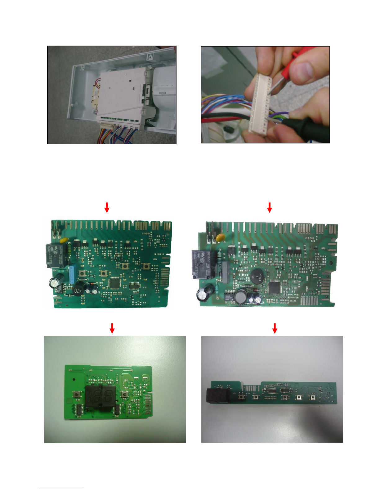
a) b)
In order to reach the connections of the electronic card; dismantle the control panel (Picture
a) and probes of the tester should be applied on to the related connectors of the electronical
card; control the values according to the resistance value table. (picture b)
Free-standing and semi-ıntegrated electronic card Fully-Integrated electronic card
Free-standing and semi-ıntegrated display card Fully-Integrated display card
- 57 -
Page 58
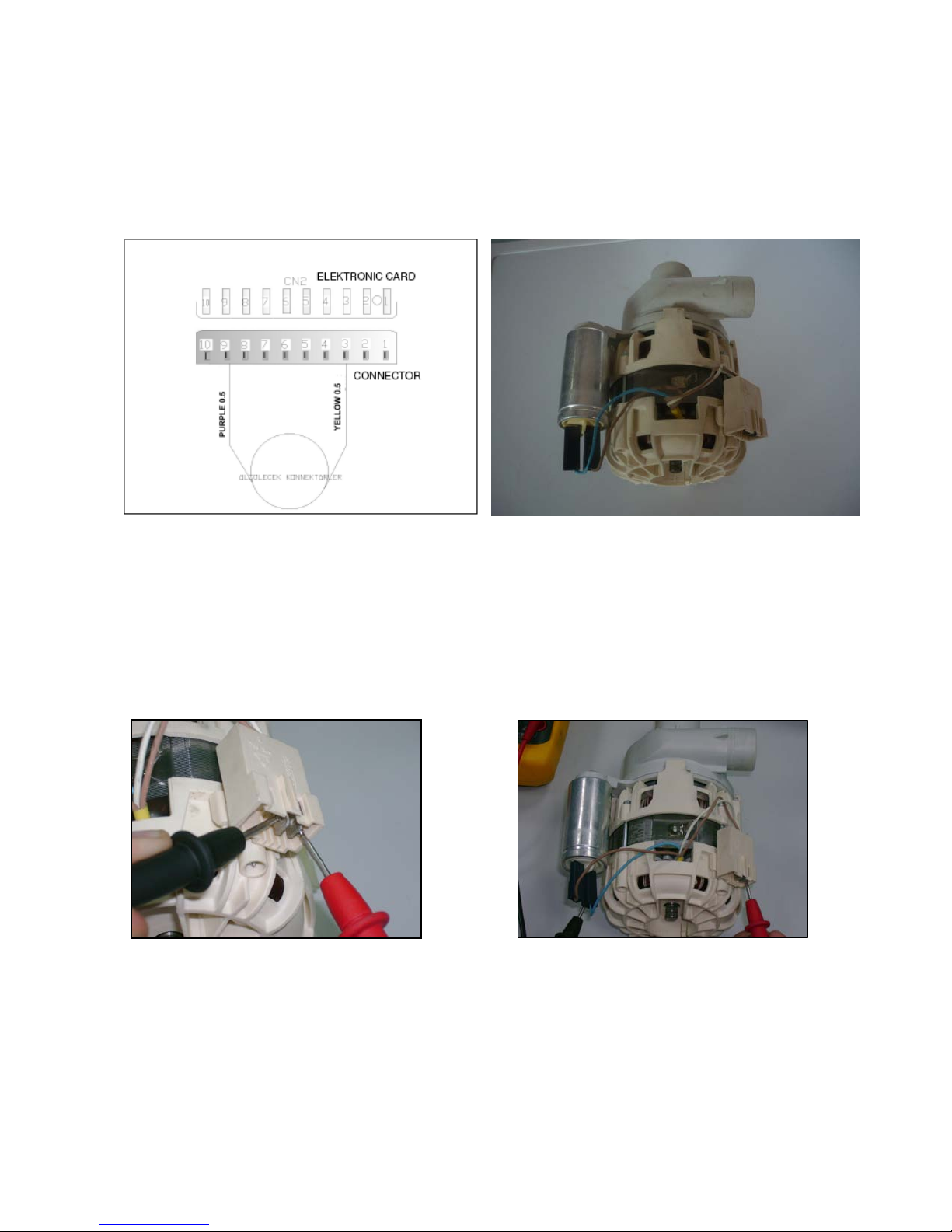
Precaution: Always remove the plug from the power socket before
touching internal
components.
Washing Pump:
From the Electronical Card:
You can only measure the primary winding value from the electronical card. Resistance
value of the primary winding must be 95 Ω on the connectors CN2.3 – CN2.9.
bove sketch show the connectors of the washing pump on the electronical card. Probes of
A
the tester should be applied on to the related connectors.
From the component:
windings of the washing pump
Probes of the tester should be applied on to the related connectors as shown on the pictures.
windings of the washing pump
– blue cable)
- 58 -
Page 59
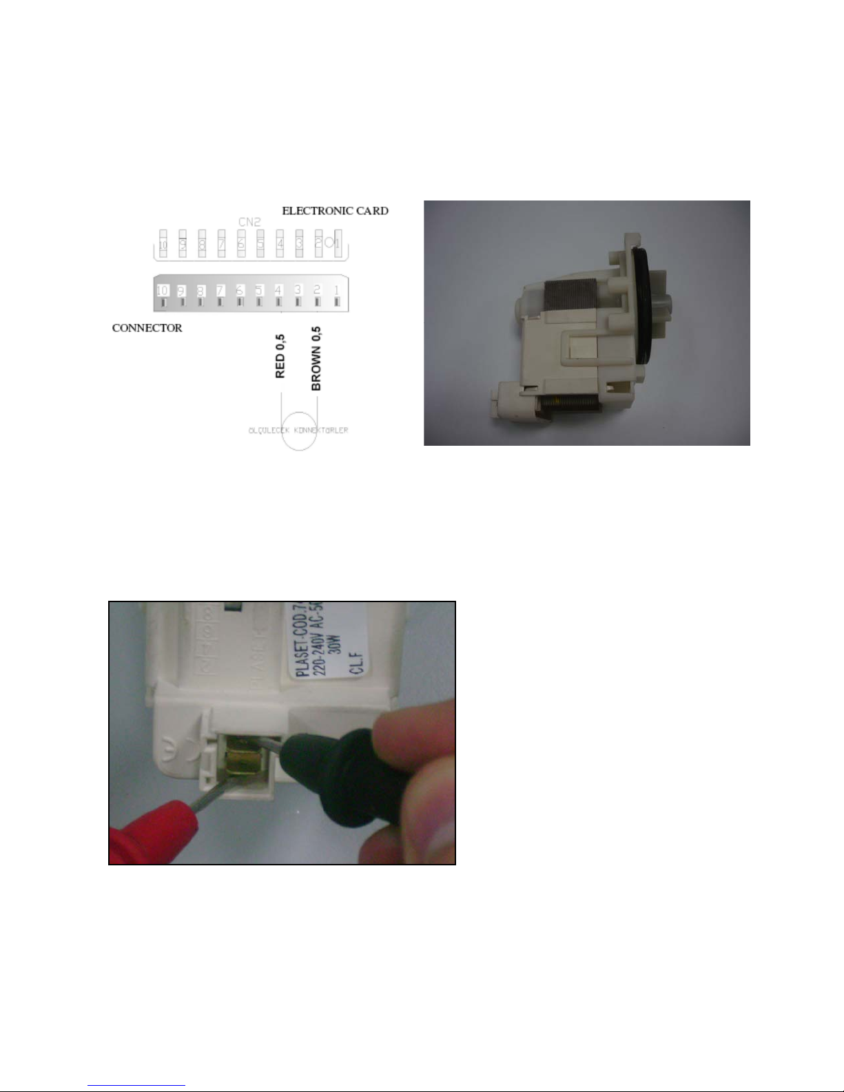
Drain Pump:
From the Electronical Card:
1
43 ± 7 Ω on the connectors CN2.2 – CN2.4
Above sketch show the connectors of the drain pump on the electronical card. Probes of the
tester should be applied on to the related connectors.
rom the component :
F
Probes of the tester should be applied on to the related connectors as shown on the pictures
- 59 -
Page 60
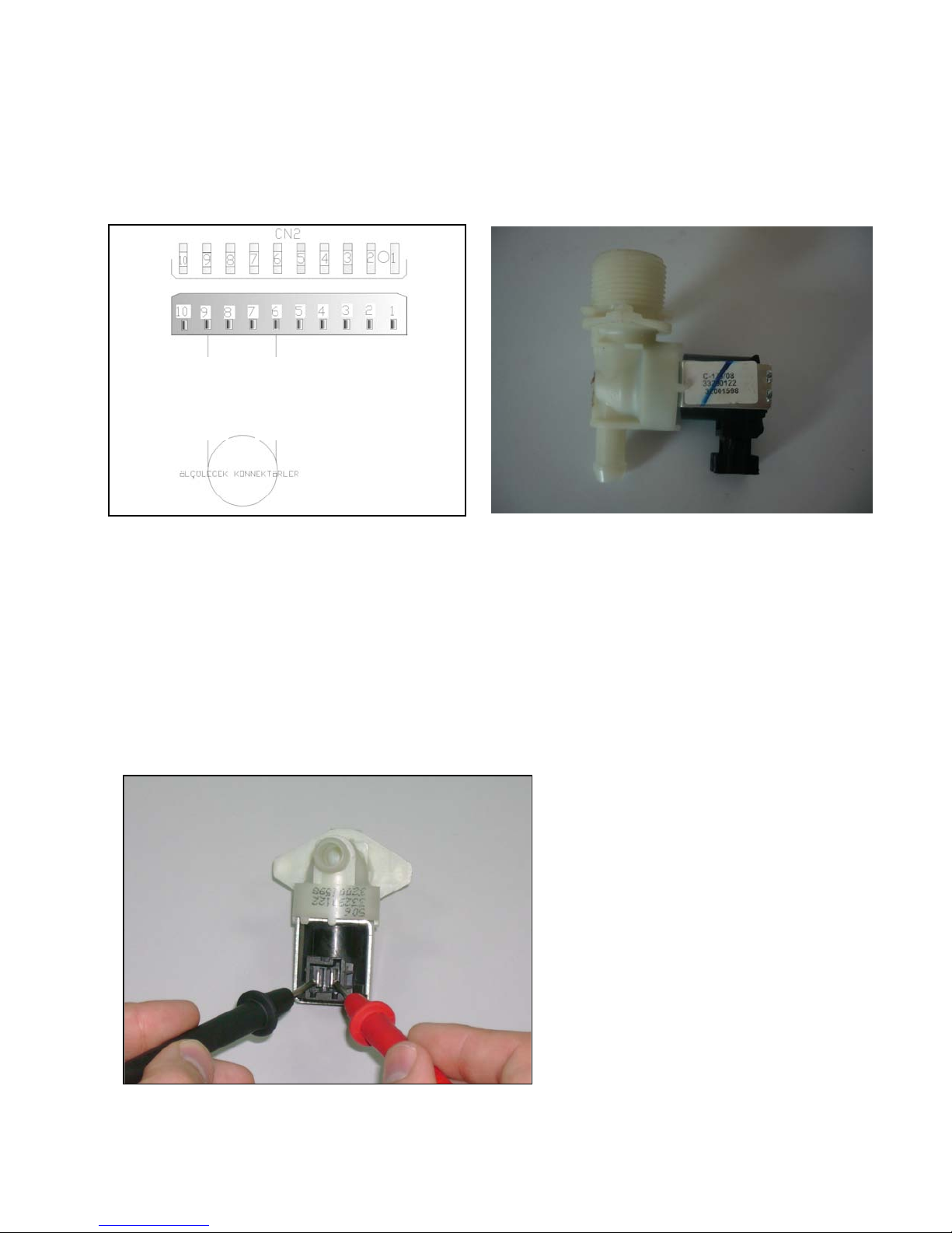
Water inlet valve:
F
rom the Electronical Card:
3750 ± 10 Ω ( 20 Cº) on the connectors CN2.6 – CN 2.9
ELECTRONIC CARD
CONNECTOR
PURPLE 0,5
Above sketch show the connectors of the water inlet valve on the electronical card. Probes of
the tester should be applied on to the related connectors.
From the component:
CONNECTOR
BLUE 0,5
BLUE 0,5
Probes of the tester should be applied on to the related connectors as shown on the pictures.
- 60 -
Page 61
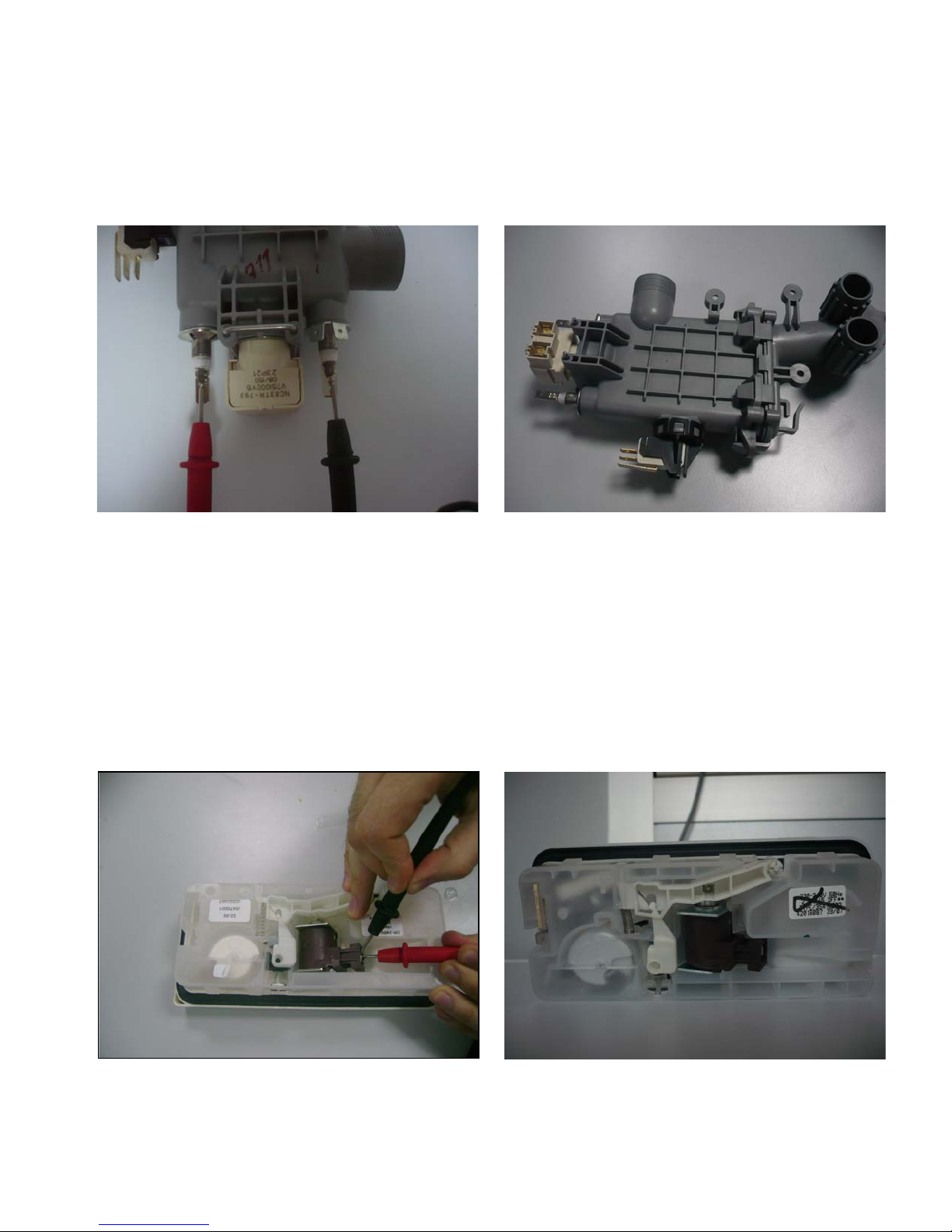
Heater Casing:
It can’t be measured from the electronical card.
F
rom the component:
23.95 ±15 Ω
Probes of the tester should be applied on to the related connectors as shown on the pictures.
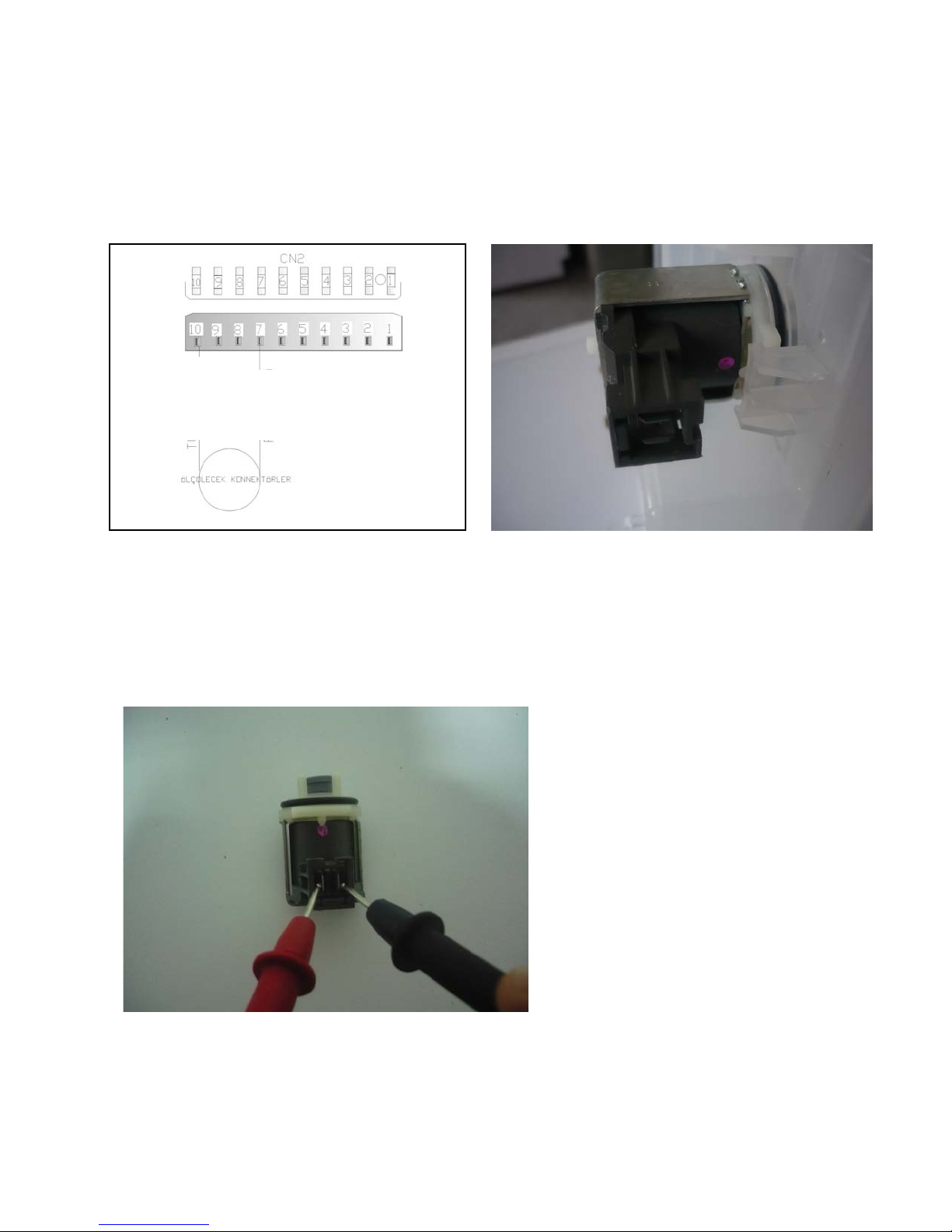
Detergent Dispenser:
t can’t be measured from the electronical card.
I
1660 ± 10 Ω (25 C º)
From the component:
Probes of the tester should be applied on to the related connectors as shown on the pictures
- 61 -
Page 62
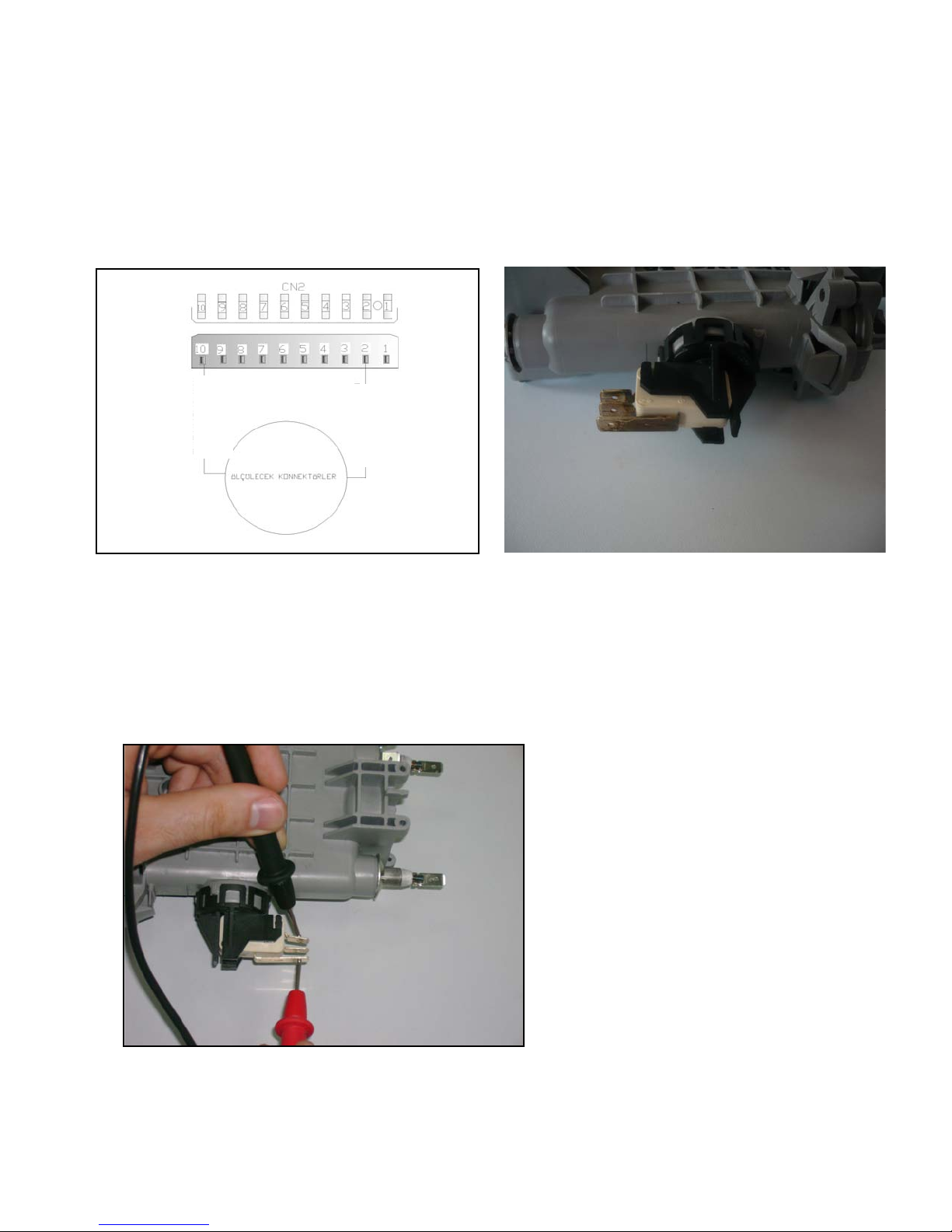
R
egenaration Valve:
From the Electronical Card:
4130 ± 10 Ω (25 C º) on the connectors CN2.10 – CN2.7
ELECTRONIC CARD
ORANGE 0,5
Above sketch show the connectors of the regeneration valve on the electronical card. Probes
of the tester should be applied on to the related connectors.
From the component:
CONNECTOR
PINK 0,5
Probes of the tester should be applied on to the related connectors as shown on the pictures.
- 62 -
Page 63
0 Ω There is water (Full)
not water (Empty)
Pressure Switch:
From the Electronical Card:
C
N2.10 – CN2.2
ELECTRONIC CARD
ORANGE 0,5
Above sketch show the connectors of the pressure switch on the electronical card. Probes of
the tester should be applied on to the related connectors.
From the component:
∞ Ω There is
CONNECTOR
BROWN 0,5
Probes of the tester should be applied on to the related connectors as shown on the pictures.
- 63 -
Page 64
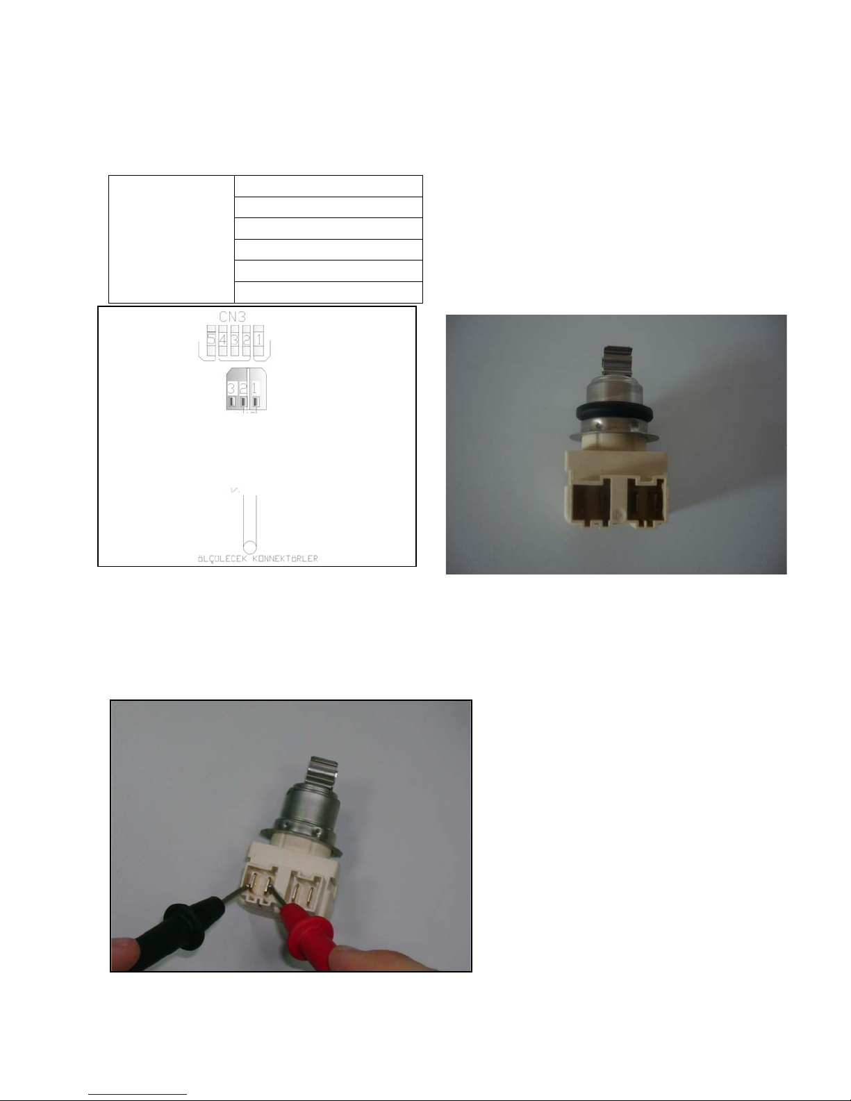
NTC sensor:
From the Electronical Card:
25°-5000Ω-%±5.0
35°-3300Ω-%±5.5
CN 3.1 - CN 3.2
CONNECTOR
Above sketch show the connectors of NTC sensor on the electronical card. Probes of the
tester should be applied on to the related connectors.
From the component:
55°-1520Ω-%±6.5
63°-1174Ω-%±7.5
80°- 670Ω -%±8.0
90°- 488Ω -%±8.5
ELECTRONIC CARD
BLACK 0,35
RED 0,35
Probes of the tester should be applied on to the related connectors as shown on the pictures.
- 64 -
Page 65
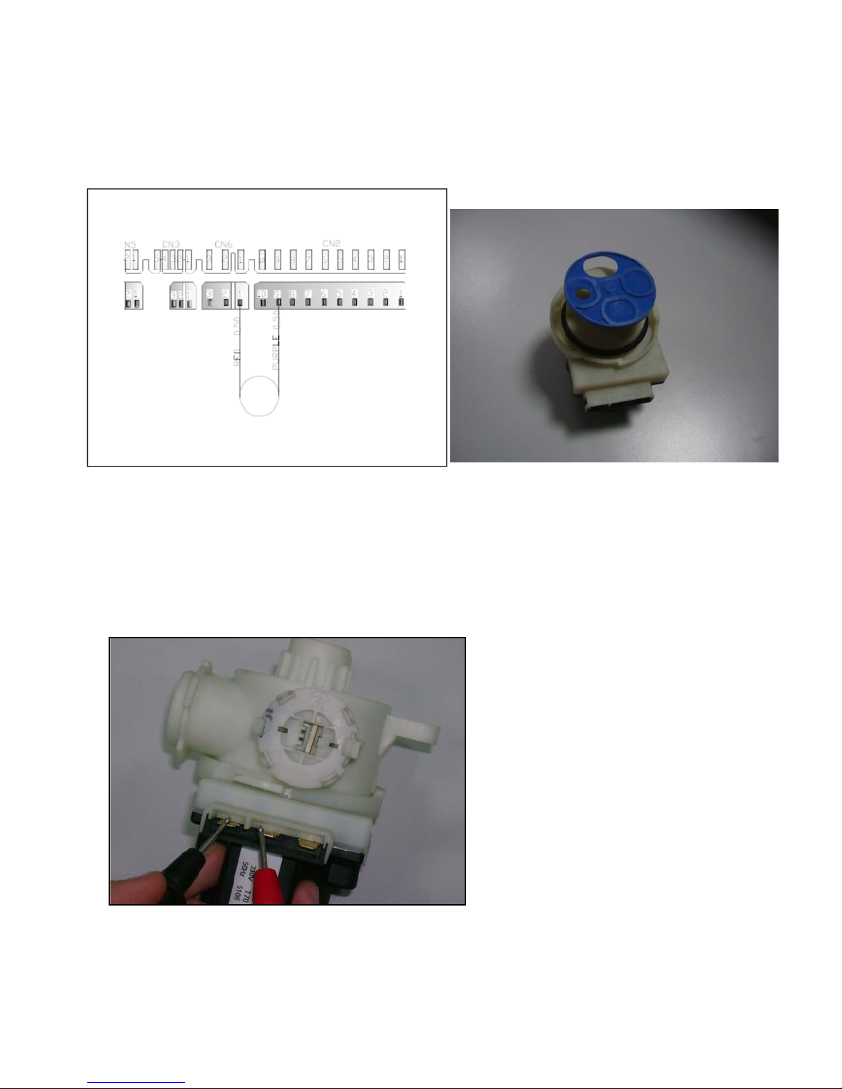
Diverter:
From the Electronical Card:
6840 Ω-%±5.0 on the connectors CN6.1 – CN 2.9
Sketch above show the connectors of the diverter on the electronical card. Probes of the
tester should be applied on to the related connectors.
From the component:
RED
Probes of the tester should be applied on to the related connectors as shown on the pictures.
- 65 -
Page 66
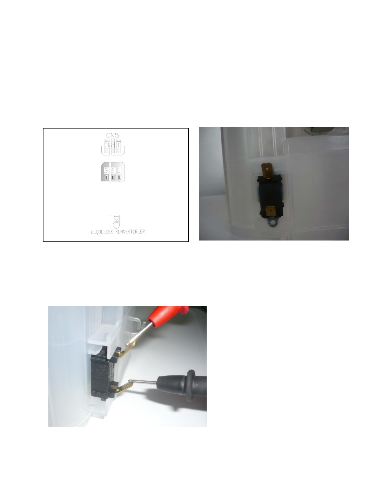
0 Ω NO SALT
CONNECTOR
Salt Sensor:
From the Electronical Card:
CN5.1 – CN5.2
∞ Ω THERE IS SALT
ELECTRONIC CARD
BLACK 0,35
RED 0,35
Sketch above show the connectors of the salt sensor on the electronical card. Probes of the
tester should be applied on to the related connectors.
RED
From the component :
Salt sensor can also be
measured from the water
softener when the salt sensor
assemblied on the water
softener.
Probes of the tester should be applied on to the related connectors as shown on the pictures.
- 66 -
Page 67
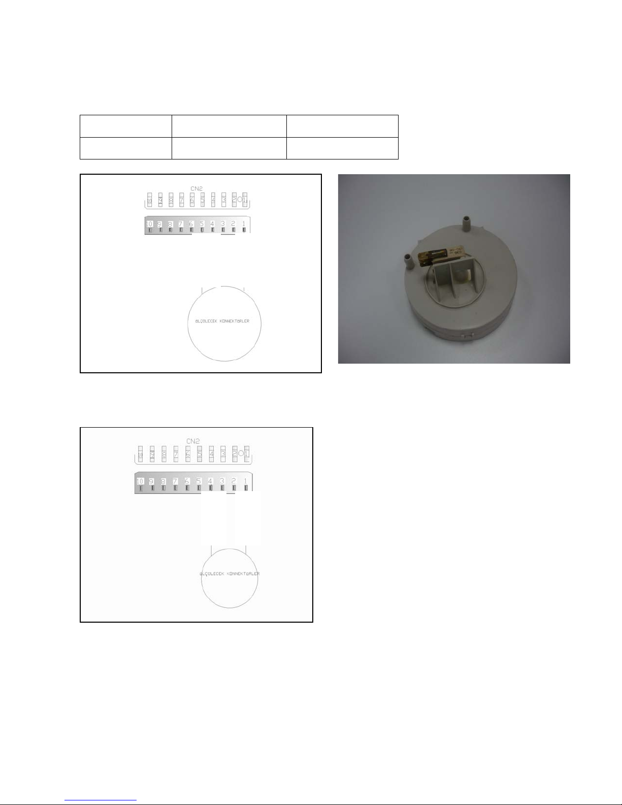
CN 2.5
MİCROSWITCH IS INACTIVE
MİCROSWITCH IS ACTIVE
FLOATER:
From the Electronical Card:
C
N2.1 –
0 Ω (Position1)
(NO WATER)
CN2.1–CN2.4 ∞ Ω (Position2)
( WATER)
ELECTRONICAL CARD
BLACK 0,5
WHITE 0,5 WHITE 0,5
Position 1: You can check the floater by controlling the specified value intervals.
ELECTRONIC CARD
RED 0,5
Position 2: If failure code is occured related with the floater within control the above values;
you can figure out whether leakage occurs or not.
- 67 -
Page 68
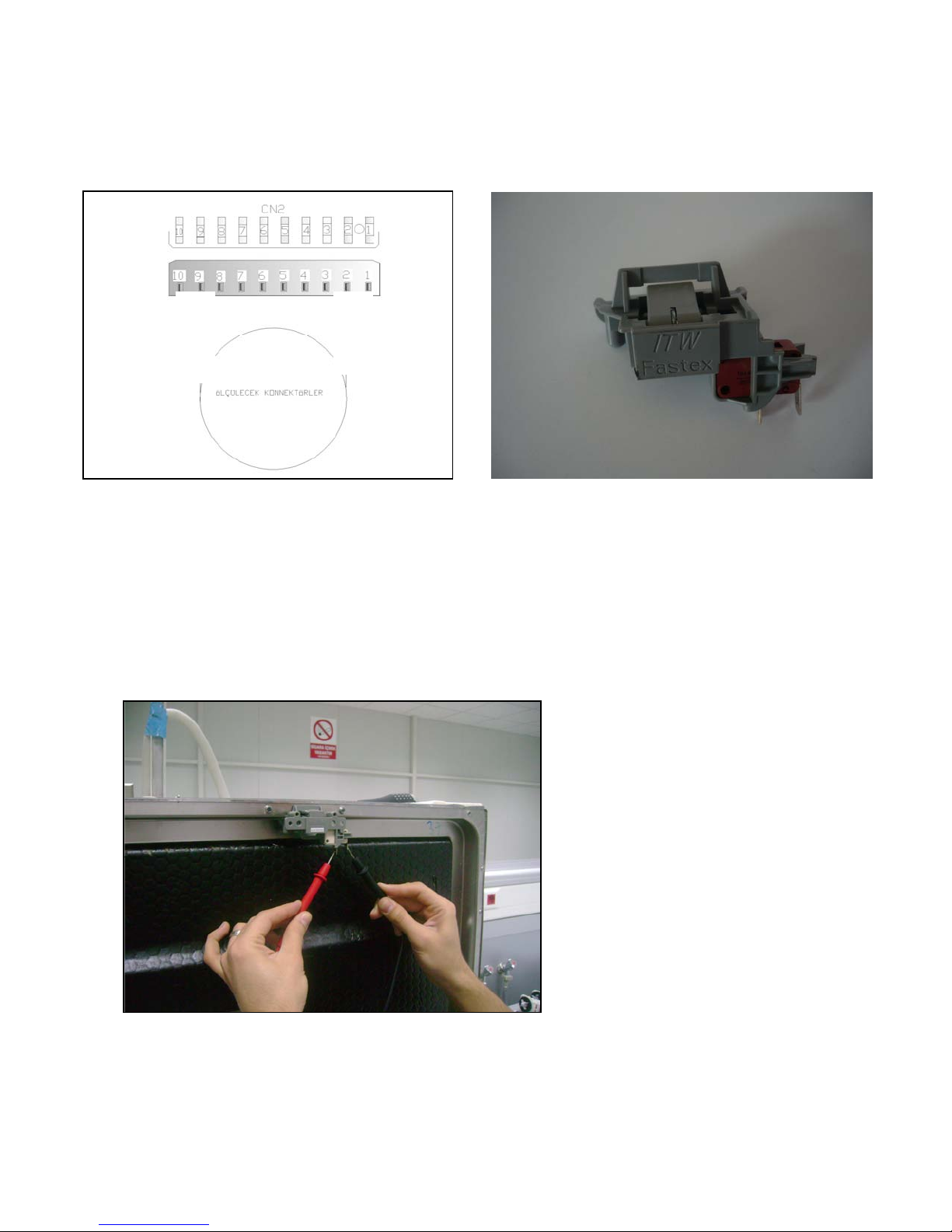
Door Switch :
From the Electronical Card:
0 Ω on the connectors CN2.9 – CN2.2 ( Door is close )
CONNECTOR
PURPLE 0,5
Above sketch show the connectors of the door switch on the electronical card.
From the component:
ELECTRONC CARD
BROWN 0,5
Probes of the tester should be applied on to the related connectors as shown on the pictures.
- 68 -
Page 69
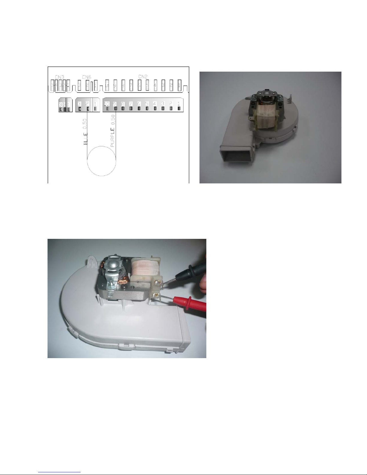
Fan Motor:
From the Electronical Card:
2
38.6 Ω ± % 5 on the connectors CN 6.2 – CN 2.9
Above sketch shows the connectors of the fan motor on tke electronical card.
From the component :
Probes of the tester should be applied on to the related
connectors as shown on the pictures.
- 69 -
Page 70
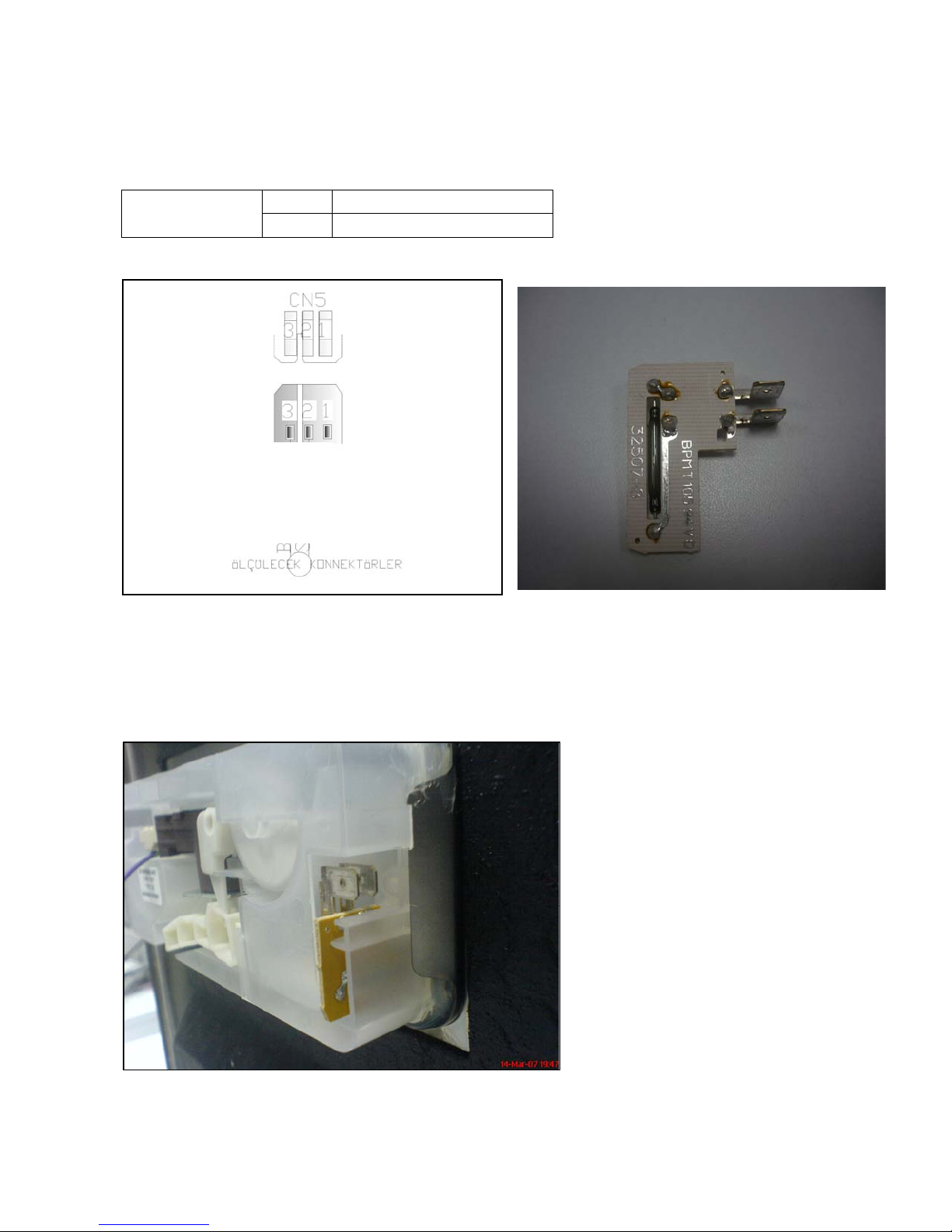
R
inse Aid Sensor:
From the Electronical Card:
CN 5.2 – CN 5.3
0 Ω
∞ Ω
Above sketch shows the connectors of the rinse aid sensor on tke electronical card.
From the component :
There isn’t any rinse aid
There is rinse aid
ELECTRONIC CARD
CONNECTOR
WHITE 0,35
BLACK 0,35
Probes of the tester should be applied on to the related connectors as shown on the pictures.
- 70 -
Page 71
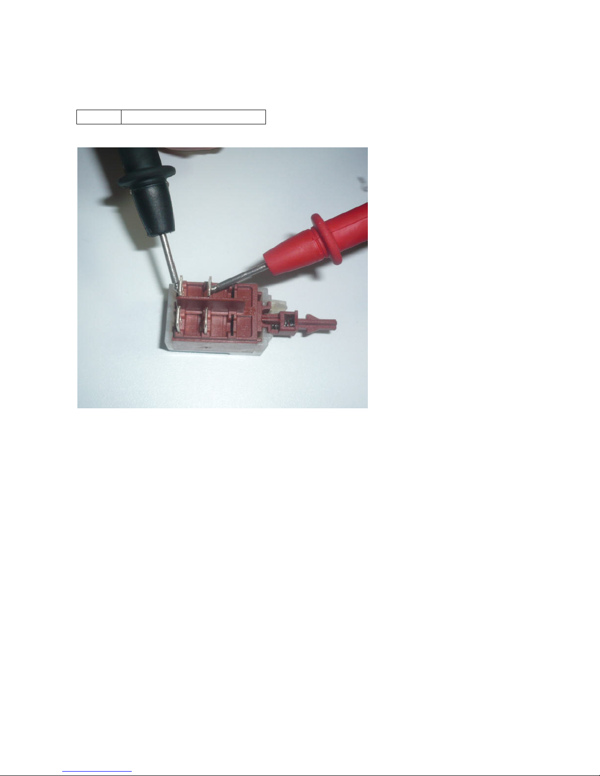
On/Off Button:
It can’t be measured from the electronical card
F
rom the component:
0 Ω
When the button is pressed
- 71 -
Page 72
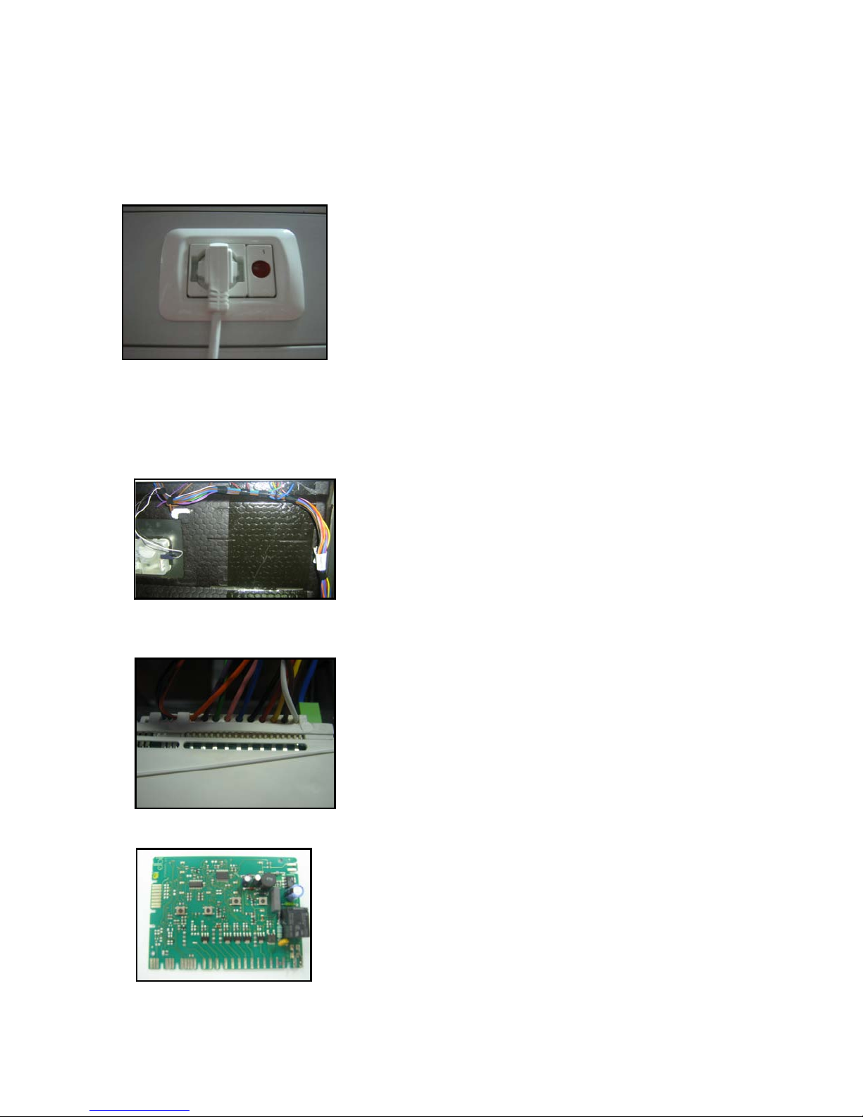
ADDITIONAL INFORMATIONS
Machine does not work.
1-Check the plug is connected or not.
2-Control supply voltage.
3- Control the supply cord.
4- Control cable connections.
5-Control the connector connections of pcb card.
6-Control the pcb card.
- 72 -
Page 73
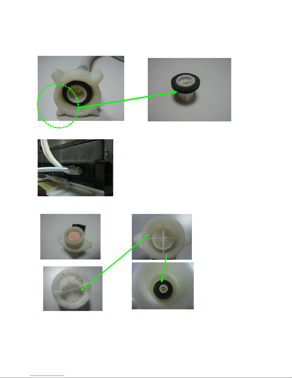
Lack of water/ less amount of water.
1- Be sure that the water inlet tap is turned on.
2- Be sure that the pressure of the supply water is enough.
3- Control the electrical connections of the water inlet valve.
4- Be sure that the water inlet valve filter are not clogged if be clogged; clean the filter.
5- Check the connection of the water inlet valve and water inlet hose.
6- Control the water inlet valve filter ; if it is clogged,clean the filter.
Filtre should be cleaned.
Also filter inside should be cleaned.
7- After these operations; failure still continue; please change the water inlet valve.
- 73 -
Page 74
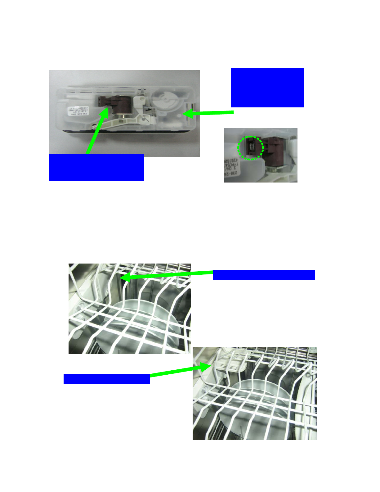
Opened Position
dispenser
Also you can control
N
ot to take the detergant / Not to melt
1- There is a mechanical or electrical problem on the detergant dispenser. If it is; please
change the detergant dispenser.
the mechanical parts of
the dispenser during
energising
Energise the connectors externally
and control the working of the
2- Customer can load the lower basket with big plates and these plates can block the
opening of the dispenser cover.
Below pictures show the position of dispenser cover
- 74 -
Closed Position
Page 75
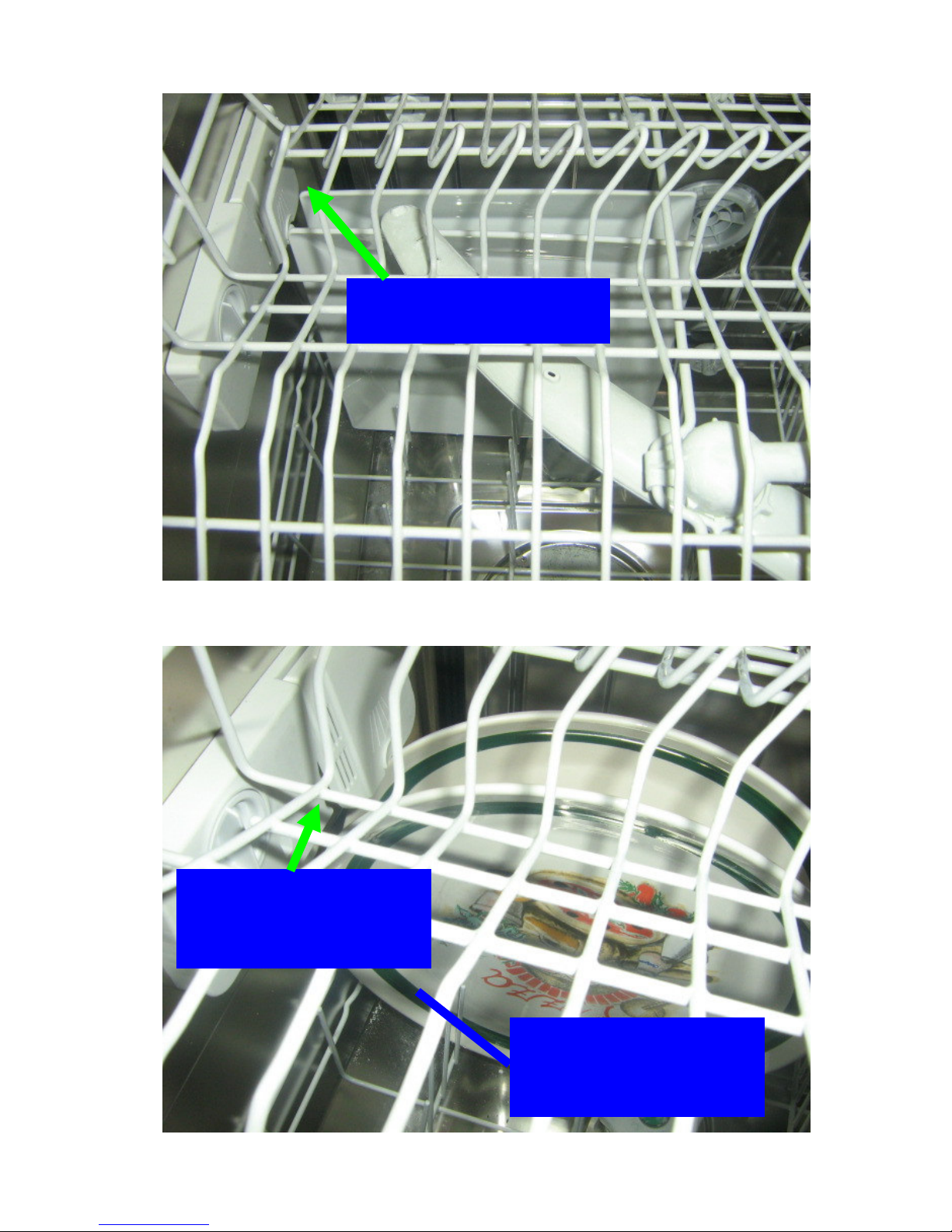
Big plates can block the
opening of the dispenser cover
Tablet detergant does not fall
inside the machine in this
position and the water may not
be enough to melt the tablet
detergant.
When the customers see the
dissolved detergant at the end
of the programme, they may
complain that ‘machine does
ot melt the detergant’.
n
- 75 -
Page 76
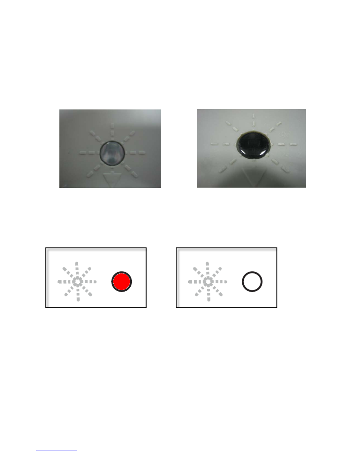
Poor drying
1- The programme which hasn’t got a drying phase; could
be informed about the programmes.
2- There might be lack of rinse aid at the rinse aid compartment.
FNPC11,FNPC12,FNPC13 haven’t got any rinse aid indicator. Control the rinse aid by using
the rinse aid level indicator
be selected.The customers should
There isn’t any rinse aid There is rinse aid
FNPC21,FNPC31 and FNAC41 have rinse aid indicator on the control panel.
There isn’t any rinse aid There is rinse aid
4- There can be mechanical or electrical problem with the detergant dispenser.
5- There can be a problem on the PCB card..
- 76 -
Page 77
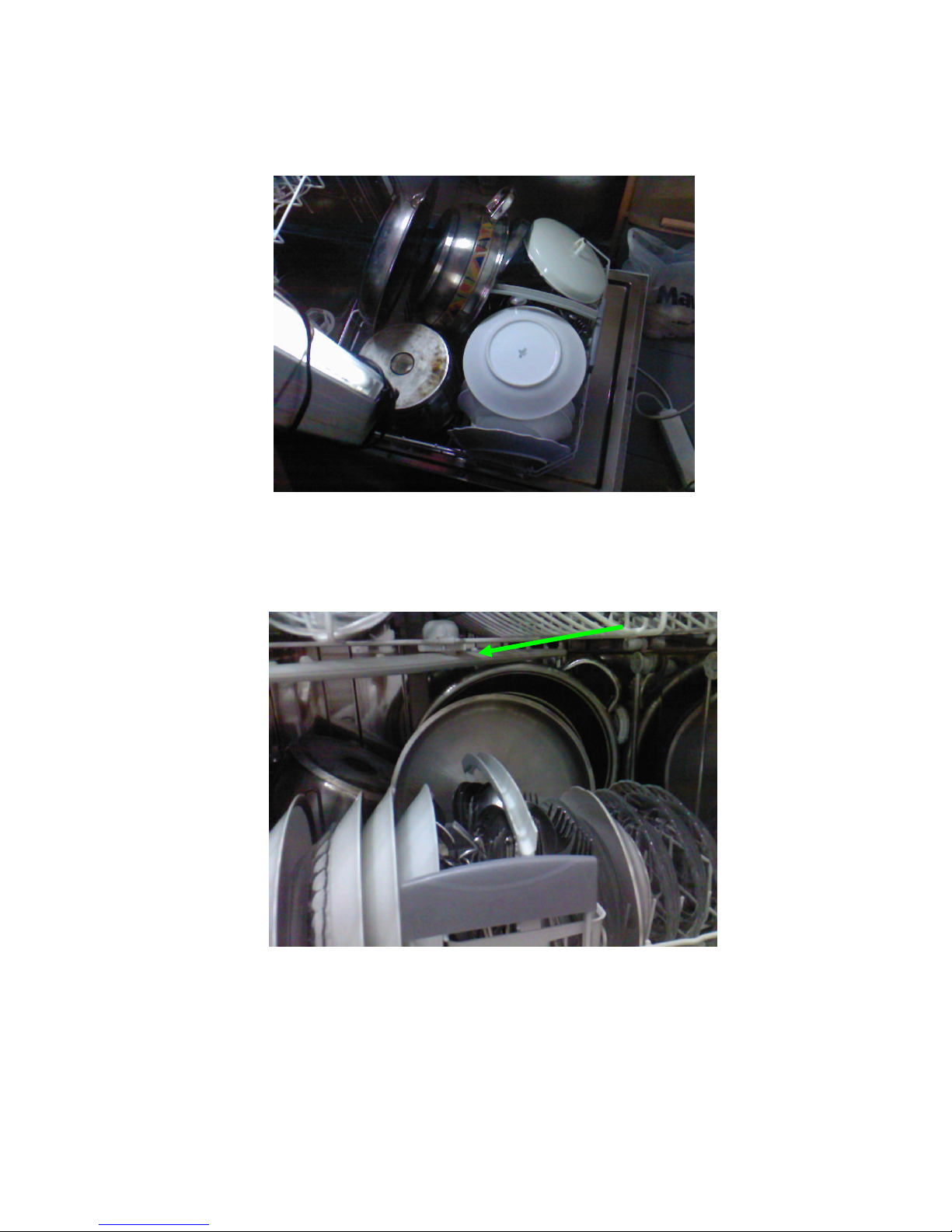
T
here are partial food wastes left on the dishes
1- Loading of the basket can not be suitable. The customers should be informed about the
loadind of the basket.
2- Unsuitable program might be selected.
3- Spray arms can be blocked by the cutleries. The customers might control the rotating of
spray arms before starting the machine.
4- There is a mechanical or electrical problem on the detergant dispenser. If it is; please
change the detergant dispenser.
5- There can be a problem with the heater casing. Check the electrical values. If there is a
problem, change the heater casing.
6- There can be a problem with the PCB card
- 77 -
Page 78
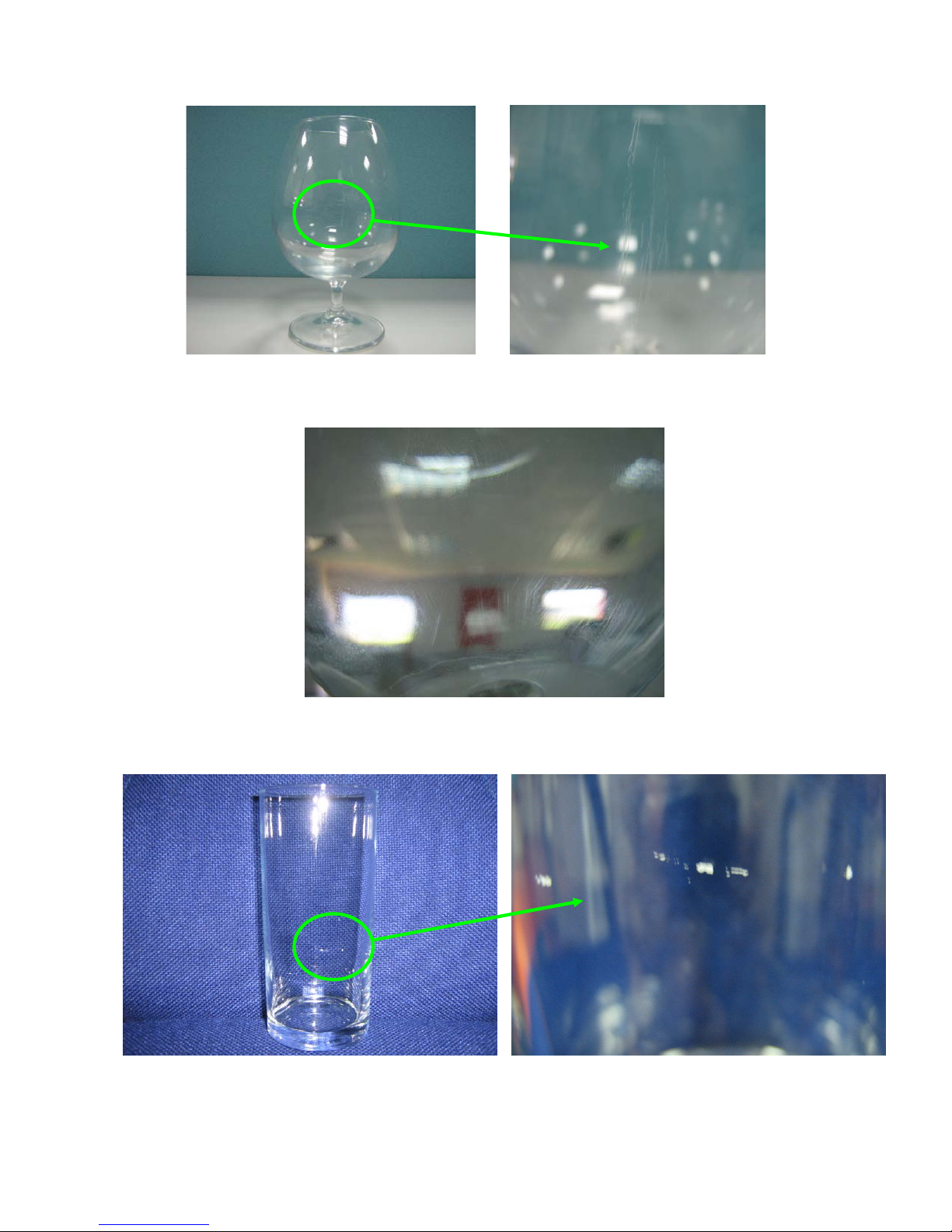
Machine scratches the glass
1-When the basket overly loaded, the glass can hit the
objects by the power of the water .
2- Substances that might be occasionaly carried in through the mains water supply can
scratch the glass.
3- Detergants which are low quality ,kept in the machine or humid places can scratch the
glass.
4-Aluminium objects should not be washed with the glass.
- 78 -
Page 79
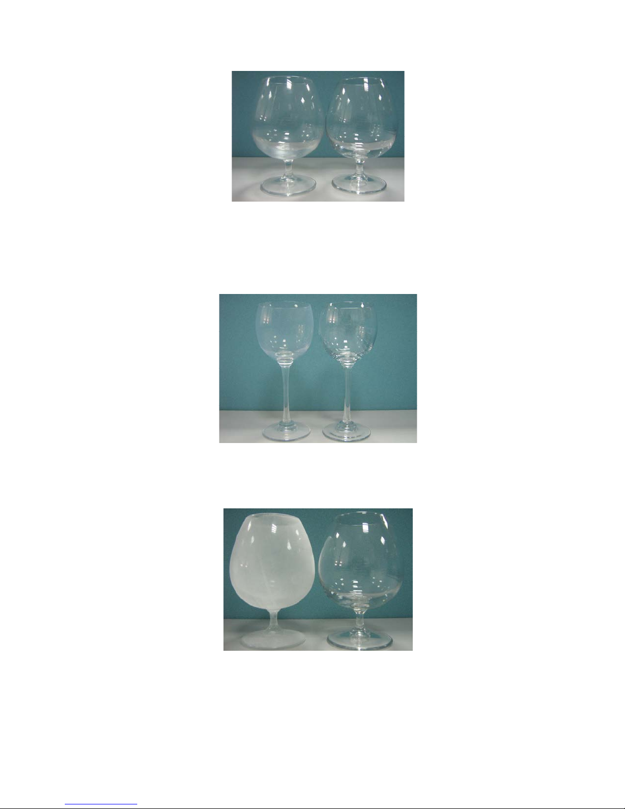
The glasses are matt after the washing
1- If there isn’t any rinse aid at the rinse aid compa
2- If the rinse aid level is very high; rainbow image can be seen on the glasses. Please adjust
the the rinse aid level to low.
3- If the water hardness is very low; stains which resembles the milk stains can be occured.
At this condition; don’t fill the salt and adjust water hardness setting to the lowest position.
rtment. Please fill with rinse aid.
4- If the salt compartment cap isn’t closed properly; matt image has been seen as shown on the
above picture.
5- If there is no salt in the salt compartment, calcification might be seen on the glass.
- 79 -
Page 80
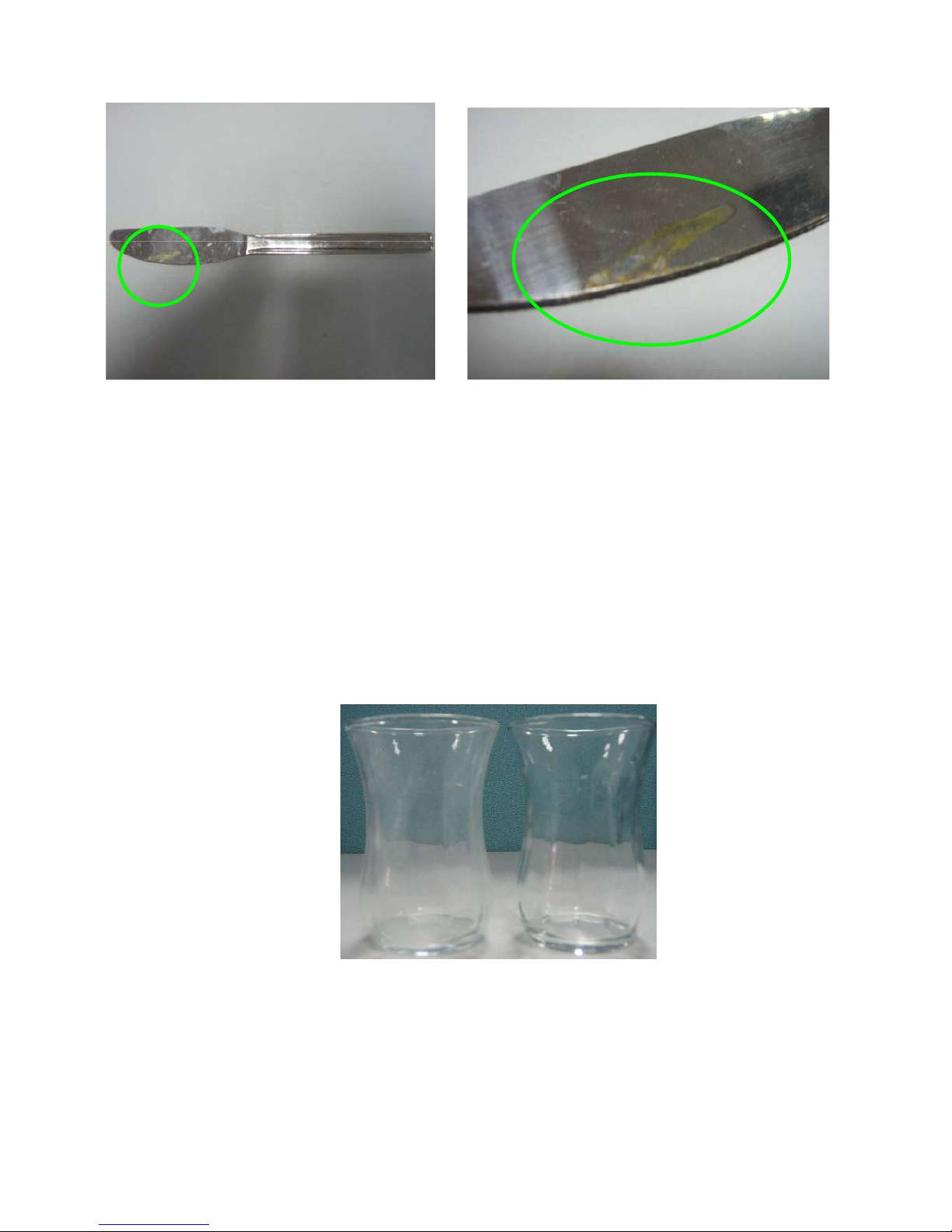
There is corrosion on the metal objects after the washing
1-Check whether there is earthing installation or not.
2-Recommend to use salt funnel while putting a salt inside the salt compartment. After
putting the salt, if there is any poured salt inside the machine, the customer should clean
there.
3 - The customers should be informed about they may face with corrosion on metal objects
which are low quality .
4-The customers should be informed about if they wash rusty materials, it may cause
corrosion on other materials.
here is calcification on the glasses after the washing
T
1- Water hardness level can be higher than adjusted level in the machine. If it is, make the
hardness adjustment. Recommend to the consumer refining the water for the region where
hardness of water is too high.
2-The salt may finish in the salt compartment. If there is no salt indicator on the machine,
the consumer should control the salt.
3-Resin may lose function.
- 80 -
Page 81

Note: After the tests, the problems that the glasses are matt or are scratched after the
washing, are not related to washing machine. They may occur with mains water supply,
unsuitable program selecting , low quality glass products and unsuitable detergant usage.
All problems base on enviromental condition and the customers usage. So the customers
should be informed about the machine and the programmes.
- 81 -
 Loading...