

Page 1
Page 2

TABLE OF CONTENTS
1. INTRODUCTION...................................................................................................................... 4
1.1. General Block Diagram.................................................................................................. 5
1.2. MB61 Placement of Blocks............................................................................................ 6
1. TUNER(TU102)......................................................................................................................... 7
1.1. General description of Samsung DTOS403LH121B:.................................................... 7
1.2. Features of DTOS403LH121B: ..................................................................................... 7
1.3. Pinning: .......................................................................................................................... 8
2. SAW FILTER – Audio – Epcos K9656M(Z101) ...................................................................... 9
2.1. Standart........................................................................................................................... 9
2.2. Features .......................................................................................................................... 9
2.3. Pin configuration ............................................................................................................ 9
2.4. Frequency response ........................................................................................................ 9
3. SAW FILTER – Video – Epcos K3958M(Z102) .................................................................... 10
3.1. Standart......................................................................................................................... 10
3.2. Features ........................................................................................................................ 10
3.3. Frequency response ...................................................................................................... 11
4. AUDIO AMPLIFIER STAGE WITH MAX9736 ................................................................... 12
4.1. General Description...................................................................................................... 12
4.2. Features ........................................................................................................................ 12
4.3. Absolute Ratings .......................................................................................................... 13
4.3.1. Electrical Characteristics.......................................................................................... 13
4.4. Pinning ......................................................................................................................... 16
5. POWER STAGE ...................................................................................................................... 17
6. MICROCONTROLLER – MSTAR(U157) ............................................................................. 19
MSD9WB7GX-LF-2.................................................................................................................... 19
6.1. MSTAR Block Diagram............................................................................................... 22
6.2. Reset Circuit................................................................................................................. 23
7. CI INTERFACE....................................................................................................................... 23
7.1 Block Diagram ............................................................................................................. 23
7.1 CI Interface Power Switch ........................................................................................... 23
8. USB INTERFACE ................................................................................................................... 24
9. DDR2 SDRAM 8M × 4 BANKS × 16 BIT (W9751G6JB) (U154, U155) ............................. 24
9.1. General Description...................................................................................................... 24
9.2. Features ........................................................................................................................ 25
9.3. Electrical Characteristics.............................................................................................. 25
9.4. Pinning ......................................................................................................................... 26
Headphone Amplifier-TDA1308 ................................................................................................. 27
Demodulators ............................................................................................................................... 28
MSB1210 ................................................................................................................................. 28
MSB1222 ................................................................................................................................. 30
CXD2820D............................................................................................................................... 31
10. SERVICE MENU SETTINGS............................................................................................. 33
10.1. Video Settings .............................................................................................................. 34
10.2. Audio Settings .............................................................................................................. 35
10.3. Options ......................................................................................................................... 36
10.4. Tuning Settings ............................................................................................................ 38
10.5. Source Settings............................................................................................................. 39
10.6. Diagnostic..................................................................................................................... 40
Page 3

10.7. USB Operations............................................................................................................ 40
11. SOFTWARE UPDATE........................................................................................................ 41
12. TROUBLESHOOTING ....................................................................................................... 42
12.1. No Backlight Problem.................................................................................................. 42
12.2. CI Module Problem...................................................................................................... 43
12.3. Led Blinking Problem .................................................................................................. 45
12.4. IR Problem ................................................................................................................... 46
12.5. Keypad Touchpad Problems ........................................................................................ 46
12.6. USB Problems .............................................................................................................. 47
12.7. No Sound Problem ....................................................................................................... 48
12.8. No Sound Problem at Headphone ................................................................................ 48
12.9. Standby On/Off Problem.............................................................................................. 49
DVD Problems ......................................................................................................................... 49
12.10. No Signal Problem ................................................................................................... 50
Page 4

1. INTRODUCTION
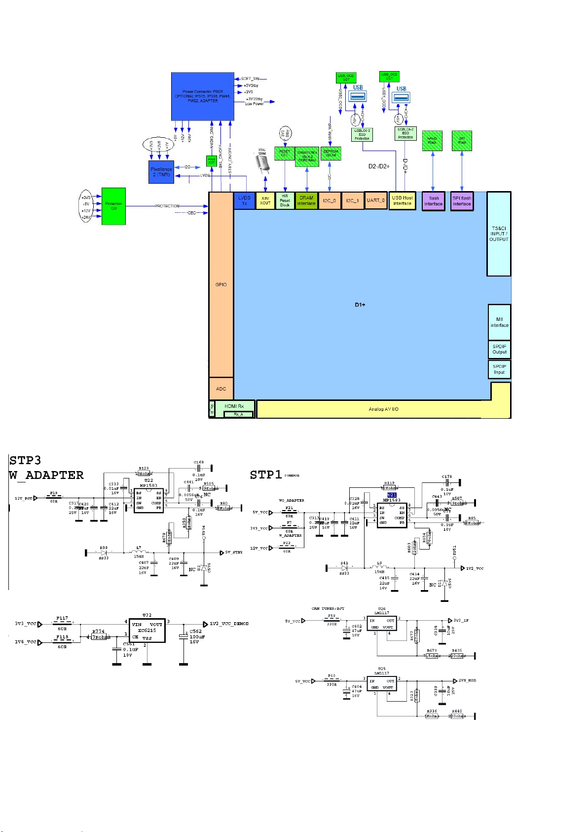
17MB61 mainboard is driven by MSD9WB7GX-LF-2. This IC is capable of handling Video
and audio processing, Scaling-Display processing, 3D comb filter, OSD and text
processing, LVDS transmitting, channel and MPEG2/4 decoding.
TV supports PAL, SECAM, NTSC colour standards and multiple transmission standards
as B/G, D/K, I/I’, and L/L’ including German and NICAM stereo. Also DVB T, DVB-C are
supported external demodulators.
Sound system output is supplying max. 2x8W (10%THD) for stereo 8
Supported peripherals are:
1 RF input VHF I, VHF III, UHF @ 75Ohm(Common)
1 Side AV (CVBS, R/L_Audio)
2 SCART socket(Common)
1 YPbPr (Common)
1 PC input(Common)
4 HDMI 1.3 input(2 HDMI inputs are common, 4 inputs are optional)
1 S/PDIF output(Common)
1 Headphone(Common)
1 Common interface(Common)
2 USB(Common)
1 DVD(Optional)
1 On-board Keypad(Optional)
1 External Keypad(Optional)
1 External TouchPad(Optional)
Ω speakers.
Page 5
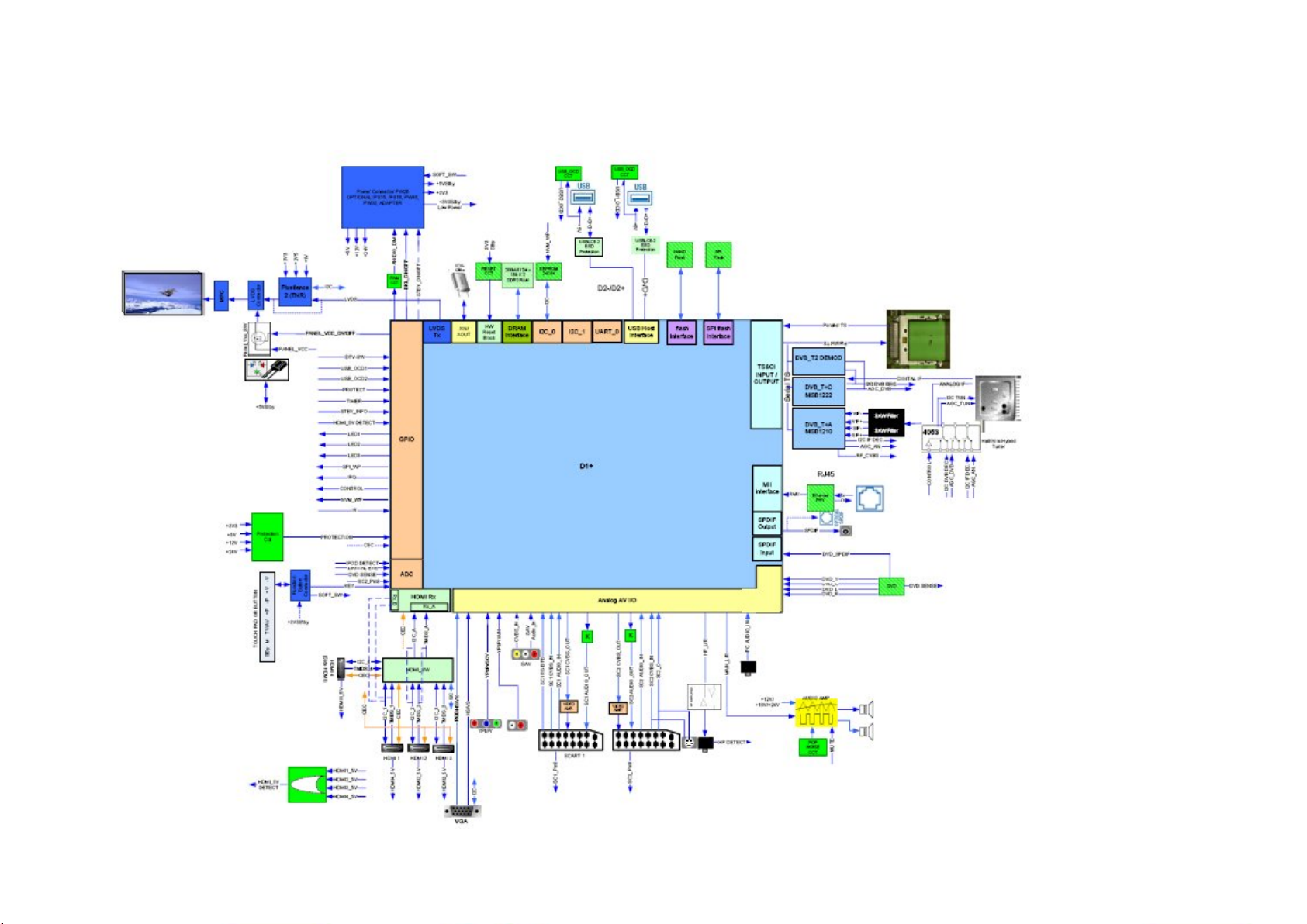
1.1. General Block Diagram
Page 6
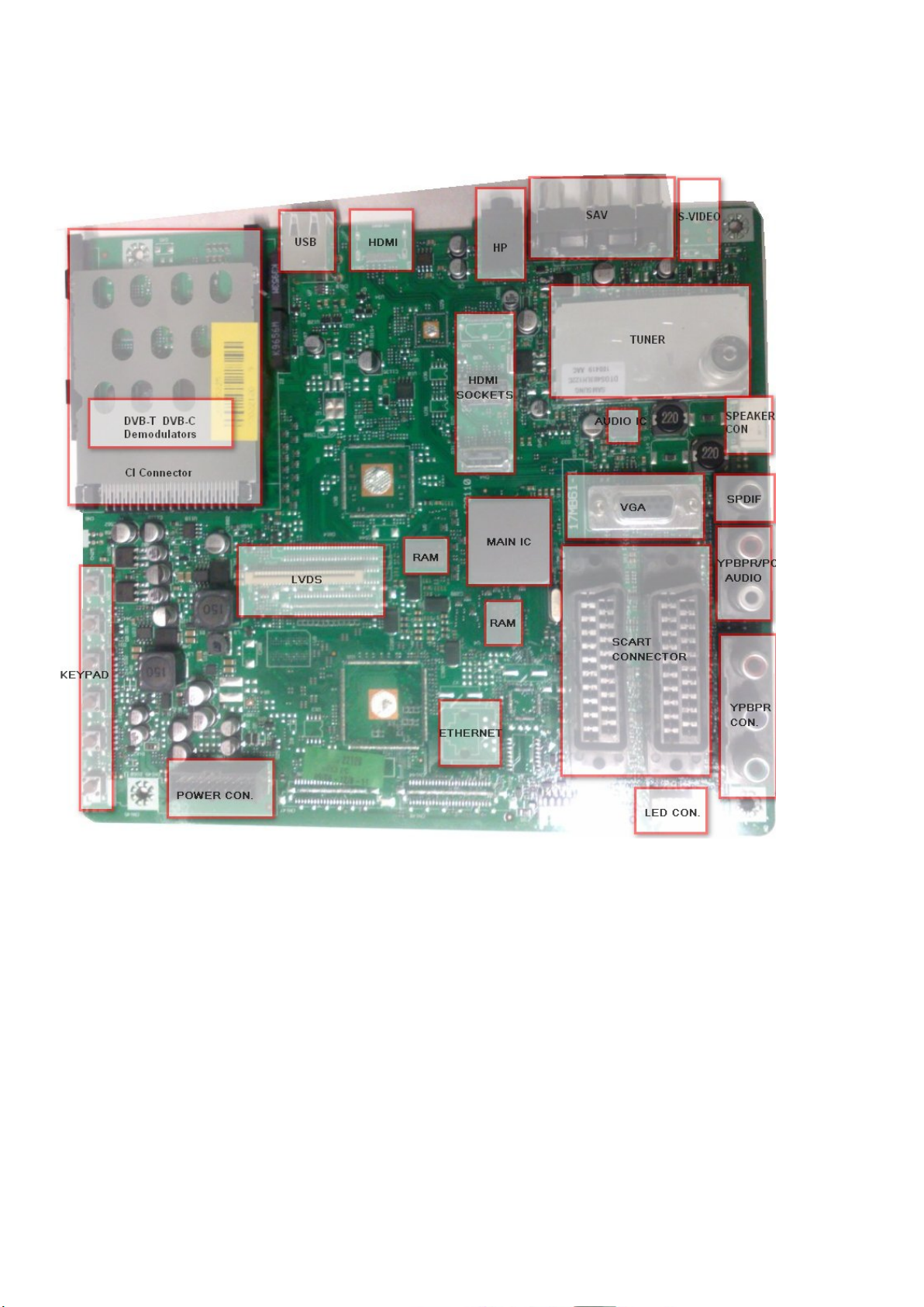
1.2. MB61 Placement of Blocks
Page 7
1. TUNER(TU102)
A horizontal mounted and Digital Half-Nim tuner is used in the product, which covers 3 Bands(From
48MHz to 862MHz for COFDM, from 45.25MHz to 863.25MHz for CCIR CH). The tuning is available
through the digitally controlled I2C bus (PLL). Below you will find info about the tuner.
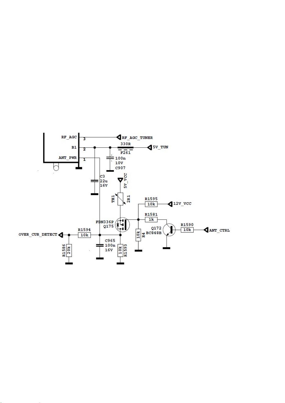
In active antenna option, the following circuit are used. ANT_CTRL pin is controlled by
microcontroller. If ANT_CTRL is low, ANT_PWR will be low. If ANT_CTRL is high, ANT_PWR will be
high.
OVER_CUR_DETECT pin is a monitor for short circuit in antenna. OVER_CUR_DETECT is low,
ANT_CTRL will be low, so ANT_PWR will be low. Finally, short circuit protection is done by circuits
and microcontroller.
1.1. General description of Samsung DTOS403LH121B:
The Tuner covers 3 Bands(from 48MHz to 862MHz for COFDM, from 45.25MHz to 863.25MHz for
CCIR CH). Band selection and Tuning are performed digitally via the I2C bus.
1.2. Features of DTOS403LH121B:
Receiving System: This TUNER is designed to cover the air channels in VHF and UHF,
compliant with DVB-T standard. and It covers all Analog channels from 48.25MHz to
863.25MHz
Receiving Channel (Digital, Center frequency):
VHF Low CH. E2 ~ S10 ( 50.5MHz ~ 170.5MHz )
VHF High CH. E5 ~ S41 ( 177.5MHz ~ 466 MHz )
Page 8

UHF CH. E21 ~ E69 ( 474 MHz ~ 858 MHz )
1
Ant Power
Active Antenna Power
3
RF AGC
RF AGC (internal or external mode)
4CLI2C Serial Clock
7
BT(T.P)
+33V, within DC/DC
circuit
9
IF AGC
Control voltage for the IF AGC
11
IF OUT
-
Output 1 of the IF Amplifier
12
AIF Output
IF output of the Analog BroadBand
Receiving Channel (PAL, Picture carrier frequency):
VHF Low CH. E2 ~ S10 ( 48.25MHz ~ 168.25MHz )
VHF High CH. E5 ~ S41 ( 175.25MHz ~ 463.25MHz )
UHF CH. E21 ~ E70 ( 471.25MHz ~ 863.25MHz )
Intermediate Frequency:
Digital(center) DVB-T (36.167 MHz)
Digital(center) DVB-C (36.125 MHz)
Analog(picture) 38.9 MHz
Input Impedance: 75Ω, Unbalanced
Band Change-Over System
PLL Control System
Tuning System
Electronic Tuning System With PLL
Internal(or External) RF AGC function
Built in wideband AGC detector with 6 programmable take-over points
1.3. Pinning:
Terminal
Pin no.
Name Pin Description
2 B+ +5V, Supply Voltage (Preamplifier, DC/DC)
5 DA I2C Serial Clock
6 BP +5V, Supply Voltage (RF Amp, PLL, IF Amp)
8 AS I2C Address Selection of the PLL
10 IF OUT + Output 2 of the IF Amplifier
Page 9
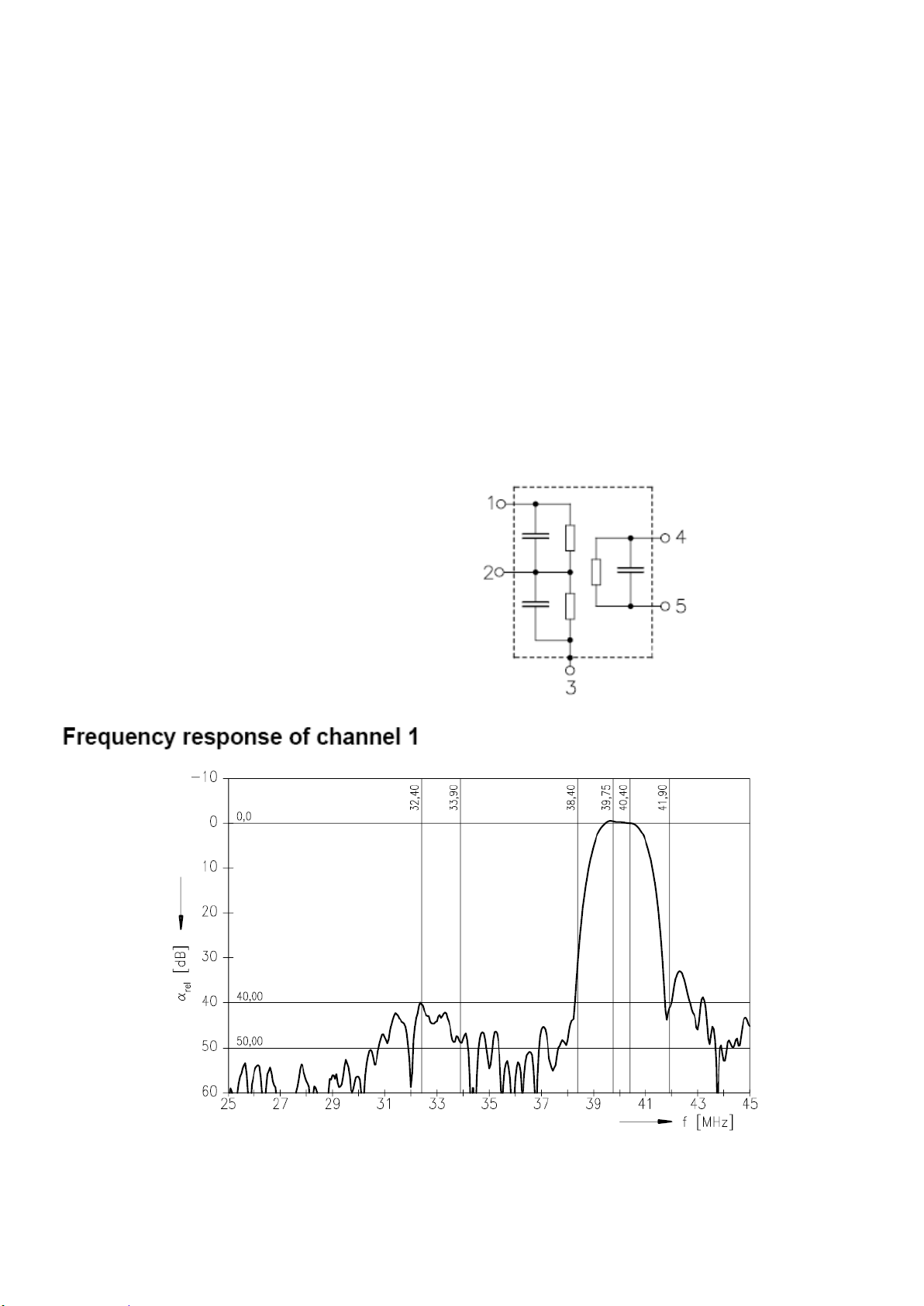
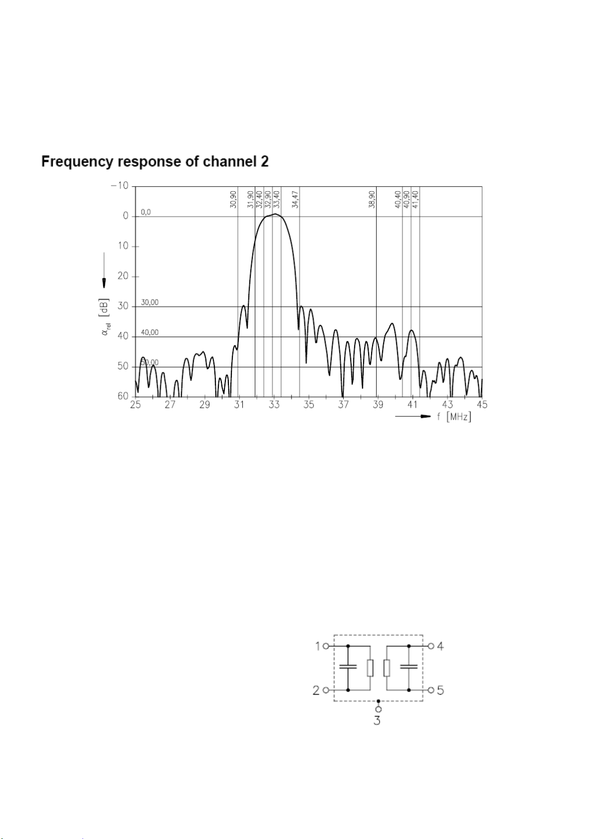
2. SAW FILTER – Audio – Epcos K9656M(Z101)
2.1. Standart
B/G
D/K
I
L/L’
2.2. Features
TV IF audio filter with two channels
Channel 1 (L’) with one pass band for sound carriers at 40,40 MHz (L’) and 39,75 MHz (L’-
NICAM)
Channel 2 (B/G,D/K,L,I) with one pass band for sound carriers between 32,35 MHz and 33,40
MHz
2.3. Pin configuration
1 Input
2 Switching input
3 Chip carrier - ground
4 Output
5 Output
2.4. Frequency response
Page 10
3. SAW FILTER – Video – Epcos K3958M(Z102)
3.1. Standart
B/G
D/K
I
L/L’
3.2. Features
TV IF filter with Nyquist slopes at 33.90 MHz and 38.90 MHz
Constant group delay
Pin configuration:
1 Input
2 Input - ground
3 Chip - carrier ground
4 Output
5 Output
Page 11
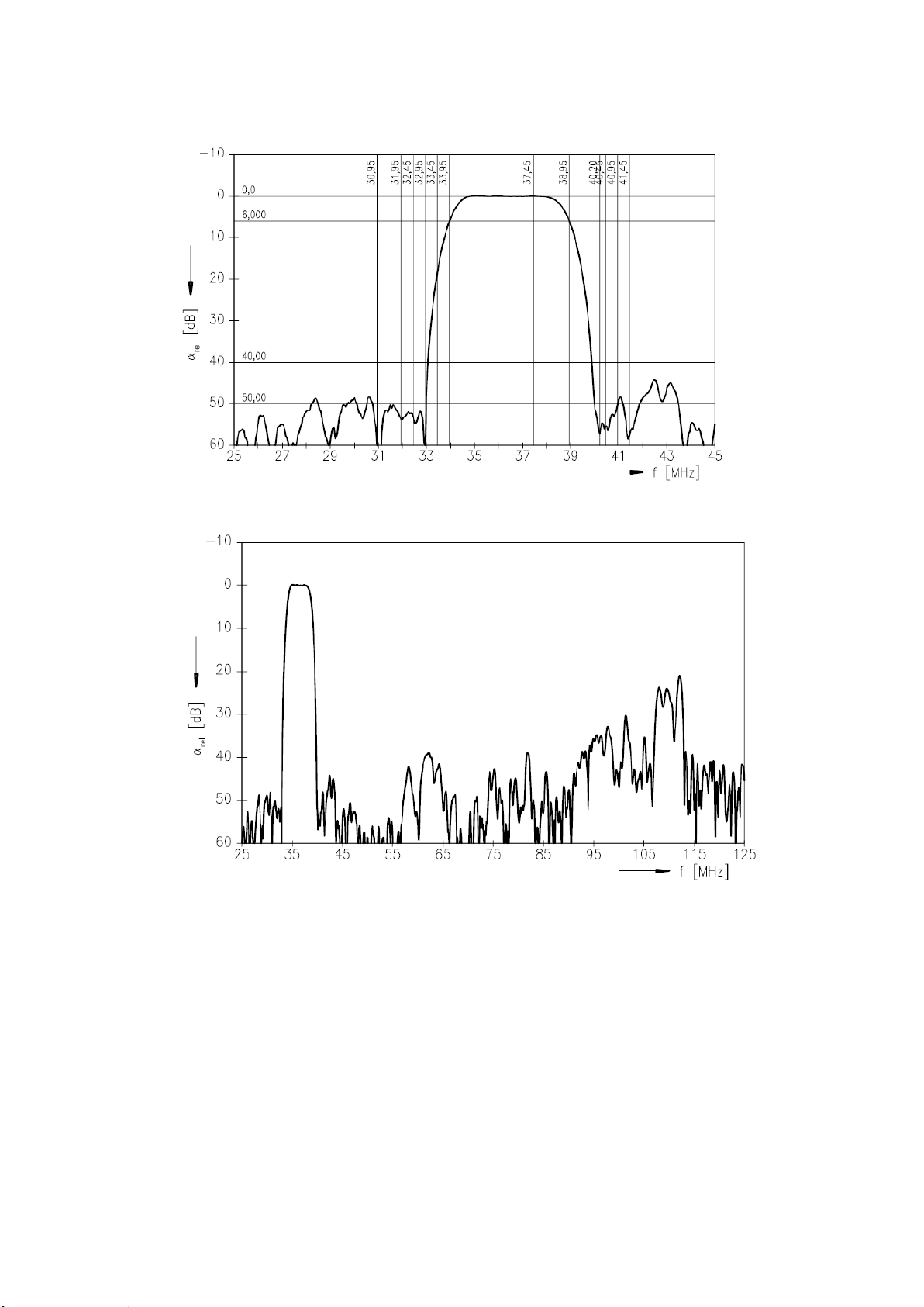
3.3. Frequency response
Page 12

4. AUDIO AMPLIFIER STAGE WITH MAX9736
4.1. General Description
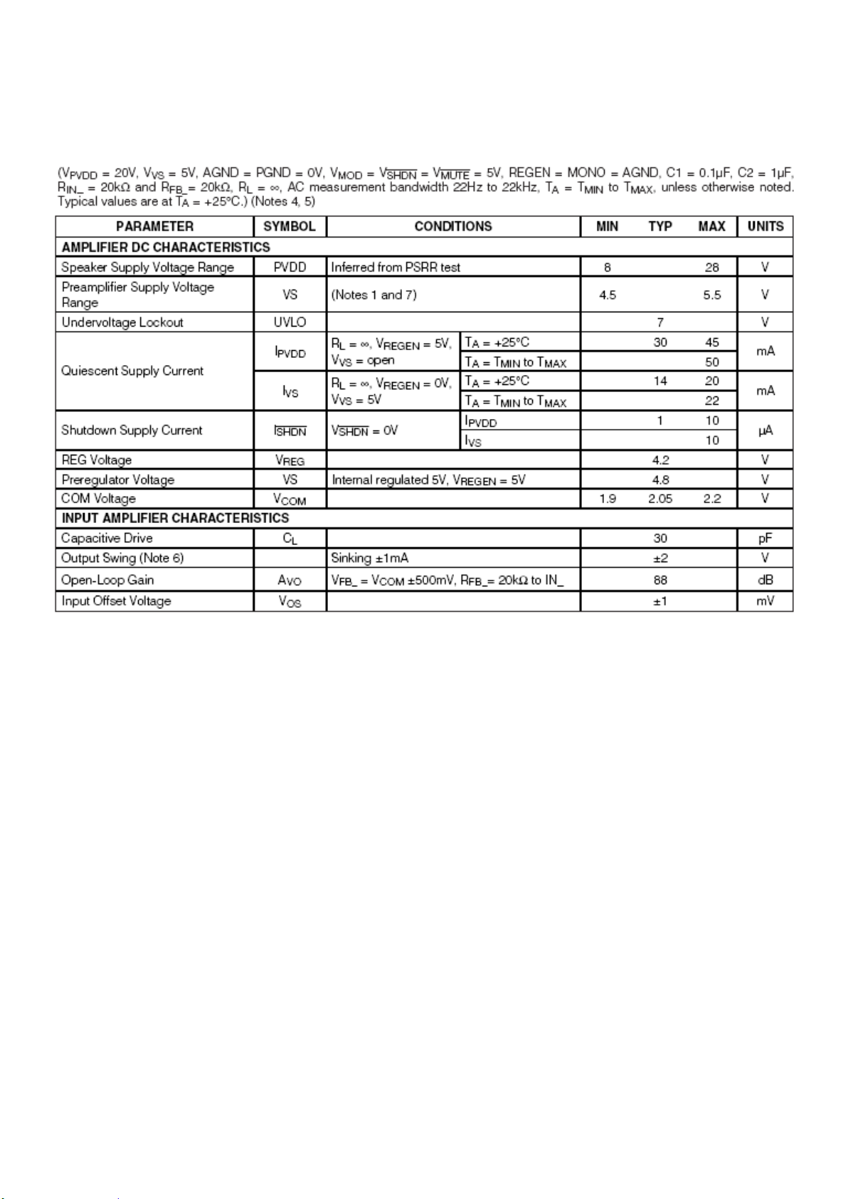
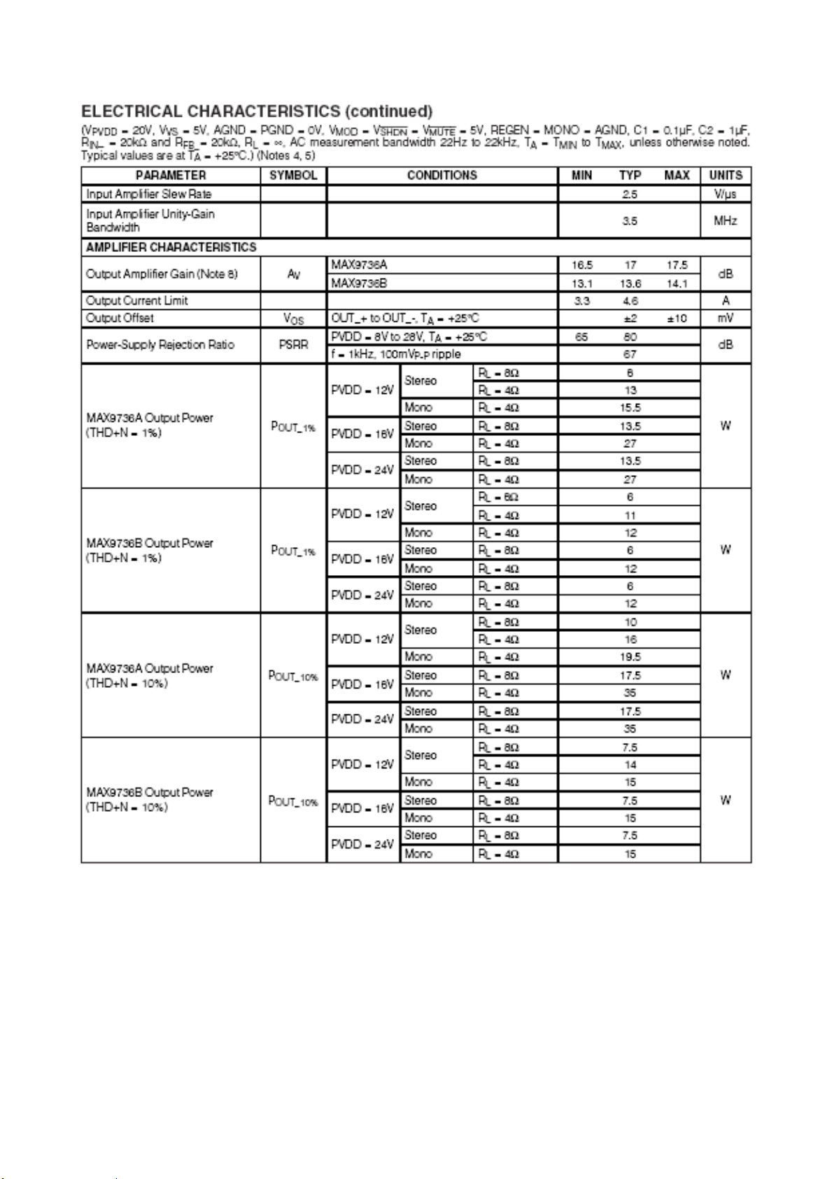
The MAX9736A/B Class D amplifiers provide high-performance, thermally efficient amplifier solutions.
The MAX9736A delivers 2 x 15W into 8
into a 4Ω load. The MAX9736B delivers 2 x 6W into 8Ω loads or 1 x 12W into a 4Ω load. These
devices are pinfor-pin compatible, allowing a single audio design to work across a broad range of
platforms, simplifying design efforts, and reducing PCB inventory.
Both devices operate from 8V to 28V and provide a high PSRR, eliminating the need for a regulated
power supply. The MAX9736 offers up to 88% efficiency at 12V supply.
Pin-selectable modulation schemes select between filterless modulation and classic PWM
modulation. Filterless modulation allows the MAX9736 to pass CE EMI limits with 1m cables using
only a low-cost ferrite bead and capacitor on each output. Classic PWM modulation is optimized for
best audio performance when using a full LC filter.
A pin-selectable stereo/mono mode allows stereo operation
loads. In mono mode, the right input op amp becomes available
as a spare device, allowing flexibility in system design.
Comprehensive click-and-pop reduction circuitry minimizes noise coming into and out of shutdown or
mute. Input op amps allow the user to create summing amplifiers,
lowpass or highpass filters, and select an optimal gain.
The MAX9736A/B are available in 32-pin TQFN packages and specified over the -40°C to +85°C
temperature
range.
Ω loads, or 1 x 30W
into 8Ω loads or mono operation into 4Ω
4.2. Features
Wide 8V to 28V Supply Voltage Range
♦ Spread-Spectrum Modulation Enables Low EMI Solution
♦ Passes CE EMI Limits with Low-Cost Ferrite Bead/Capacitor Filter
♦ Low BOM Cost, Pin-for-Pin Compatible Family
♦ High 67dB PSRR at 1kHz Reduces Supply Cost
♦ 88% Efficiency Eliminates Heatsink
♦ Thermal and Output Current Protection
♦ < 1μA Shutdown Mode
♦ Mute Function
♦ Space-Saving, 7mm x 7mm x 0.8mm, 32-Pin TQFN
Package
Page 13
4.3. Absolute Ratings
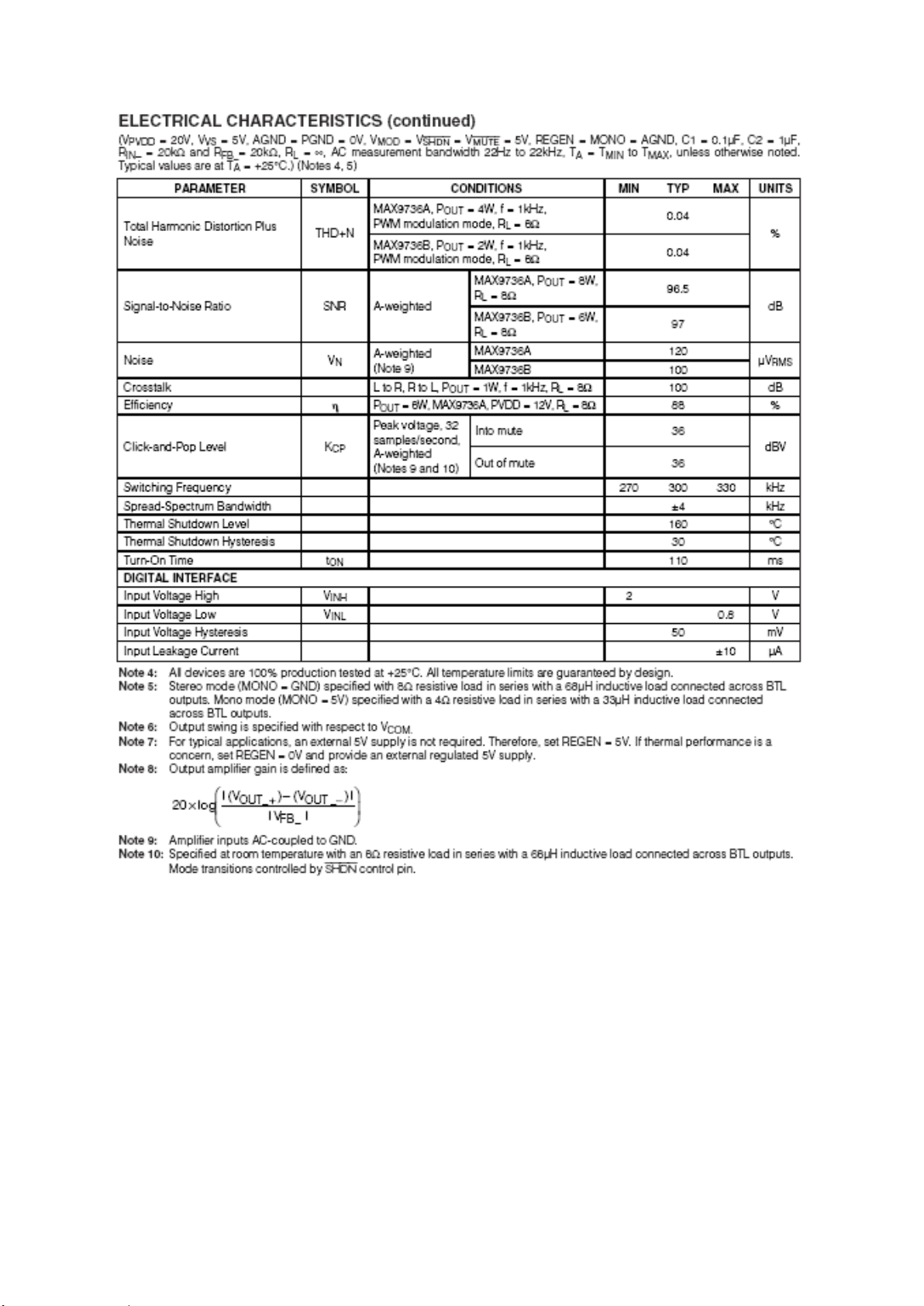
4.3.1. Electrical Characteristics
Page 14
Page 15
Page 16
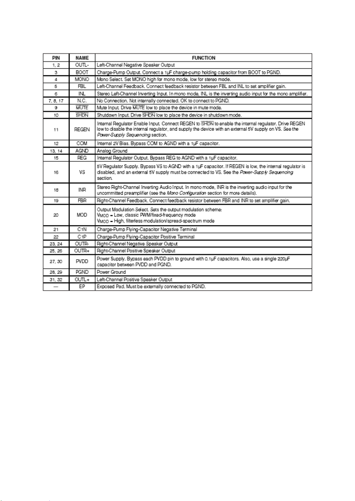
4.4. Pinning
Page 17
5. POWER STAGE
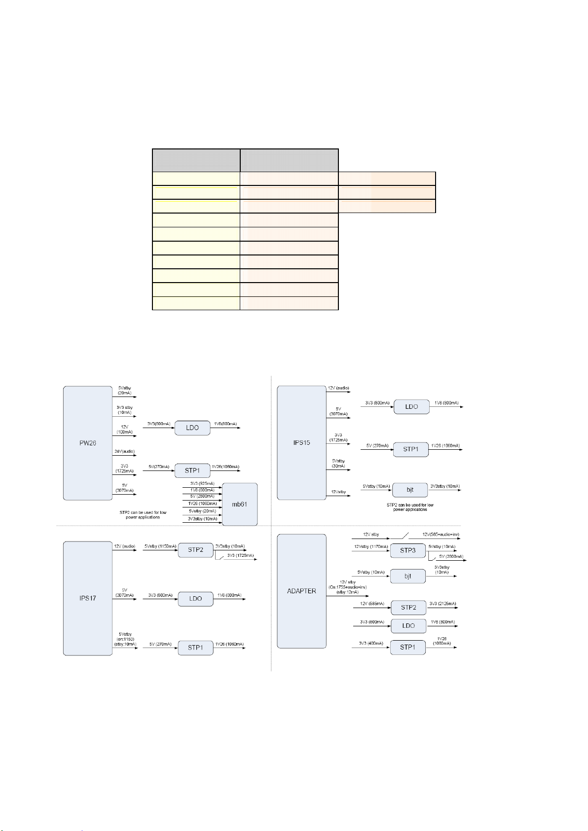
17MB61 General power management block diagram is shown below:
Voltage Total Current
3V3 925mA
3V3 stby 10mA
5V 2800mA 1500mA PANEL
5V stby 20mA
1V8 800mA
1V26 1060mA
12V 1500mA PANEL
24V 8250mA BACKLIGHT
Table 9: Power Consumption
1) These values calculated from max. ratings of existing panels. Meaning values will be lower than calculated values.
2) Total consumption value does not contain the CCFL consumption.
Page 18
Power ICs
Power Domain
Page 19

6. MICROCONTROLLER – MSTAR(U157)
MSD9WB7GX-LF-2
GENERAL DESCRIPTION
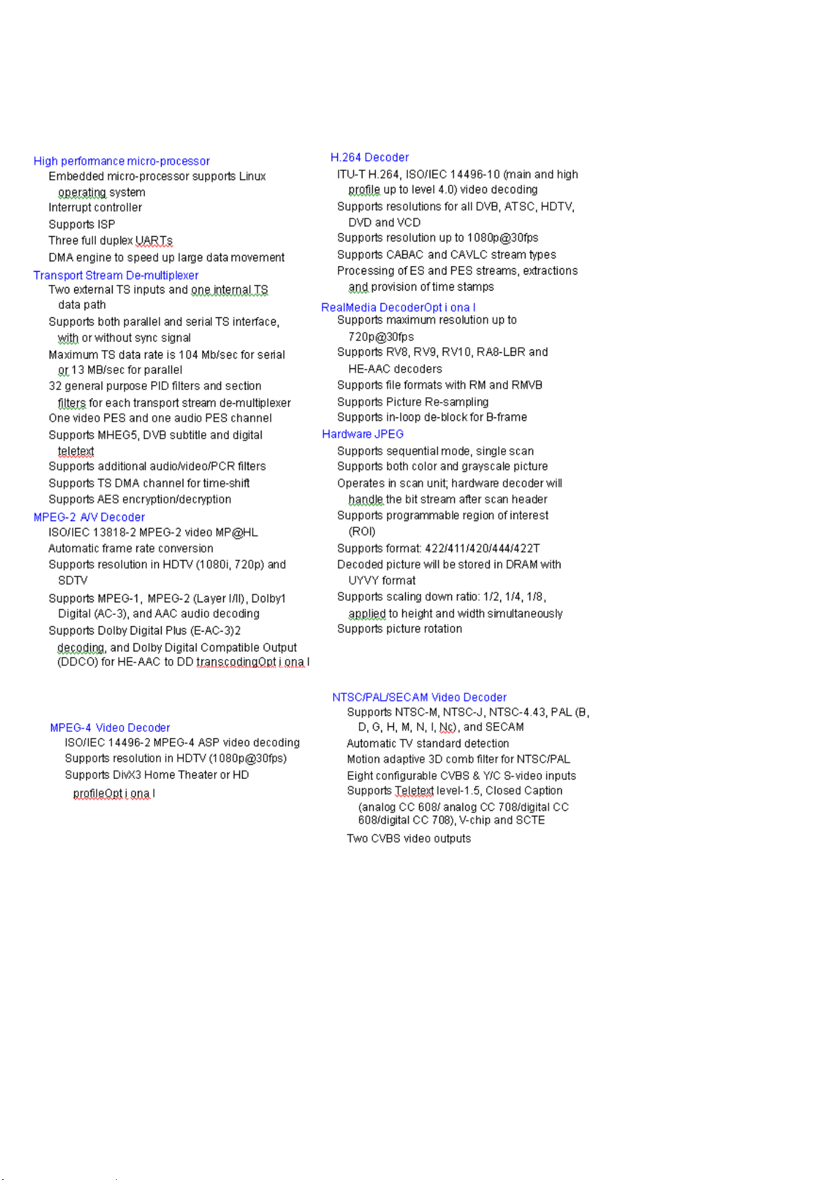
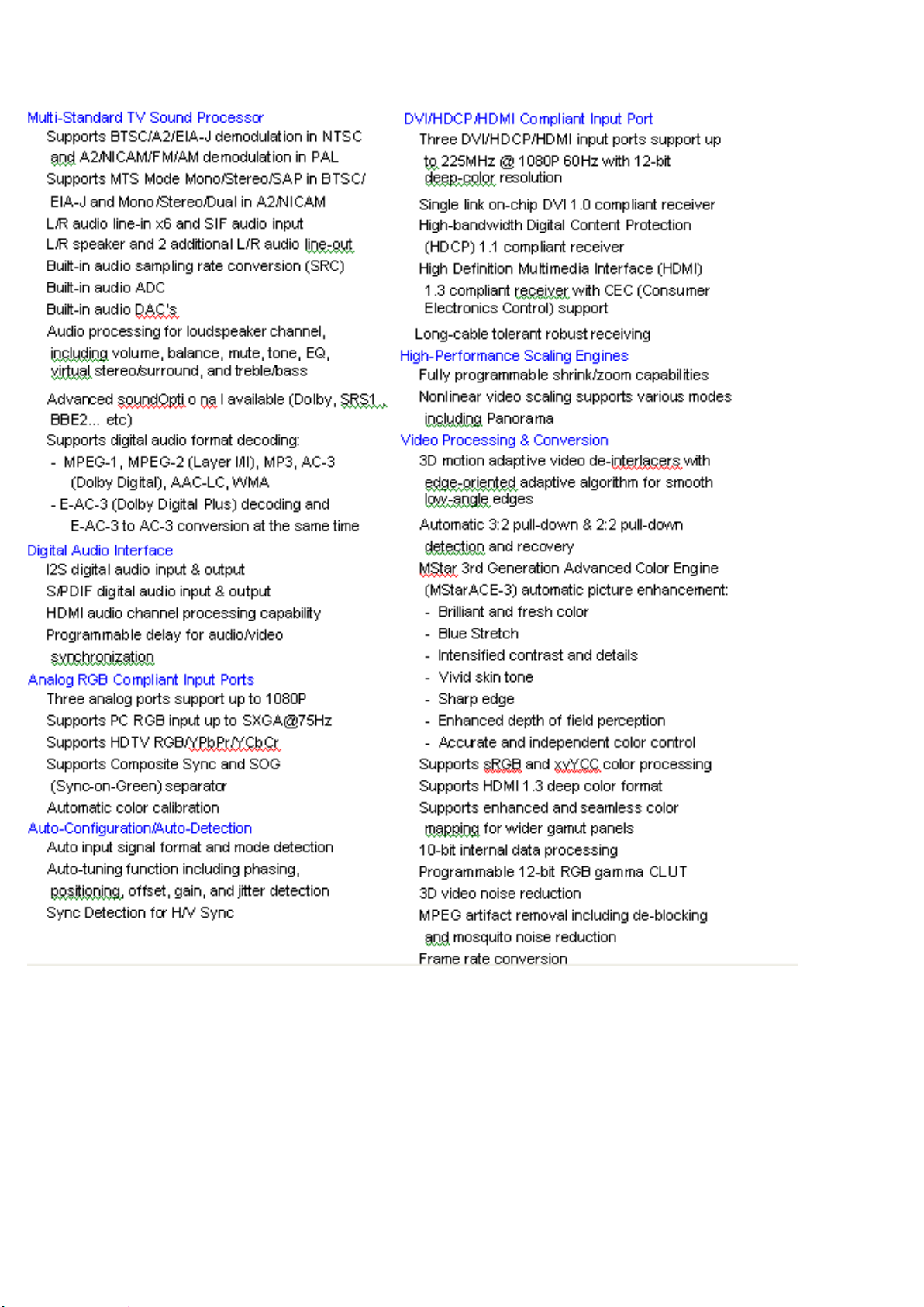
The MSD9WB7GX-2 is a highly integrated controller IC for LCD/PDP DTV applications with resolutions up to WUXGA
(1920x1200). It is configured with an integrated triple-ADC/PLL, a multi-standard TV video and audio decoder, a motion
adaptive video de-interlacer, a scaling engine, the MStarACE-3 color engine, an advanced 2D graphics engine, a transport
processor, a high-definition (HD) MPEG video decoder, a high-definition (HD) H.264
video decoder, a Real Video decoder, a JPEG video decoder, a MPEG-4 decoder, and a 24-bit DSP for MPEG audio
decoding, a DVI/HDCP/HDMI receiver, and a peripheral control unit providing a variety of HDTV control functions.
For digital TV application, the MSD9WB7GX-2 comprises an MPEG-2 transport processor with advanced section filtering
capability, an MPEG-2 (MP@HL profile) video decoder, a MPEG-4 decoder, a H.264 video decoder, and an audio DSP
decoder for MPEG audio streams, MPEG layer I and II digital audio decoder with analog audio outputs
that are designed to support existing and future DVB-T programs while handling conditional access. Furthermore, it is also
possible to decode JPEG, Real Video streams, and MP3 formats from external sources such as USB interface.
For analog TV, the MSD9WB7GX-2 includes NTSC/PAL/SECAM multi-standard video decoder comprising a 3D motion
adaptive comb filter and time-based correction, and a NICAM/A2 audio decoder to support worldwide television standards.
The MSD9WB7GX-2 is also configured with a VBI processor to decode digital information such as Close Caption/Vchip/teletext/WSS/CGMS-A/VPS. In addition, the MStar advanced LCD TV processor enhances video quality, motion
adaptive de-interlacer, picture quality adjustment units, and MStarACE-3 color engine.
With USB 2.0 host controllers, UART, IR, SPI, I2C, and PWM, the MSD9WB7GX-2 fulfills all requirements in advanced DTV
sets. Furthermore, MSD9WB7GX-2 can access files from networks with embedded Ethernet MAC and external PHY via the
MII/RMII interface. To reduce system costs, the MSD9WB7GX-2 also integrates intelligent power management control
capability for green-mode requirements and spread-spectrum support for EMI management.
Page 20
The MSD9WB7GX-LF-2 is composed of several modules:
Page 21
Page 22

6.1. MSTAR Block Diagram
Page 23

6.2. Reset Circuit
Reset circuit using for initiliazing main Mstar IC. Reset condition is high and nomal
working condition is low for RESET pin.
7. CI INTERFACE
7.1 Block Diagram
7.1 CI Interface Power Switch
It is used for CI module supply, when Module is inserted (it means CI detect is low) This
circuit is opened or closed by CI_POWER_CTRL port of main uController
Page 24

8. USB INTERFACE
Main Concept IC has integrated 2 USB 2.0 interface. One of them is used for ethernet
function, the other one is used for USB connectivity for last user. Last user can play video,
picture and audio files. Also digital channels can be record to externall storage device by
this interface. All SW files can be updated with interface.
USB circuit has 3 main parts
Integrated USB 2.0 Host interface of D3 (U157)
Protection IC (U145)
Over Curent Protection IC (U149)
9. DDR2 SDRAM 8M × 4 BANKS × 16 BIT (W9751G6JB) (U154,
U155)
9.1. General Description
The W9751G6JB is a 512M bits DDR2 SDRAM, organized as 8,388,608 words × 4 banks
× 16 bits. This device achieves high speed transfer rates up to 1066Mb/sec/pin (DDR2-
1066) for general applications. W9751G6JB is sorted into the following speed grades: -18,
-25 and -3. The -18 is compliant to the DDR2-1066/CL7 specification. The -25 is
compliant to the DDR2-800 (5-5-5) or DDR2-800 (6-6-6) specification. The -3 is compliant
Page 25

to the DDR2-667 (5-5-5) specification. All of the control and address inputs are
synchronized with a pair of externally supplied differential clocks. Inputs are latched at the
cross point of differential clocks (CLK rising and CLK falling). All I/Os are synchronized
with a single ended DQS or differential DQS- DQS pair in a source synchronous fashion.
9.2. Features
Power Supply: VDD, VDDQ = 1.8 V± 0.1 V
Double Data Rate architecture: two data transfers per clock cycle
CAS Latency: 3, 4, 5, 6 and 7
Burst Length: 4 and 8
Bi-directional, differential data strobes (DQS andDQS ) are transmitted / received
with data
Edge-aligned with Read data and center-aligned with Write data
DLL aligns DQ and DQS transitions with clock
Differential clock inputs (CLK and CLK )
Data masks (DM) for write data
Commands entered on each positive CLK edge, data and data mask are
referenced to both edges of DQS
Posted CAS programmable additive latency supported to make command and data
bus efficiency
Read Latency = Additive Latency plus CAS Latency (RL = AL + CL)
Off-Chip-Driver impedance adjustment (OCD) and On-Die-Termination (ODT) for
better signal quality
Auto-precharge operation for read and write bursts
Auto Refresh and Self Refresh modes
Precharged Power Down and Active Power Down
Write Data Mask
Write Latency = Read Latency - 1 (WL = RL - 1)
Interface: SSTL_18
9.3. Electrical Characteristics
Page 26

9.4. Pinning
Page 27

Headphone Amplifier-TDA1308
The TDA1308 is an integrated class AB stereo headphone driver.
Power supply maximum 60 mW to 32Ω (THD<0.1%)
5V single supply
SNR 110 dB
Power supply ripple rejection
Page 28

Typically 3 mA supply current at no load
No switch ON/OFF clicks
Excellent power supply ripple rejection
Low power consumption
Short-circuit resistant
High performance
high signal-to-noise ratio
high slew rate
low distortion
· Large output voltage swing.
Pin configuration and description is given in Figure 16 and Table 18.
Table 18
: Pin configuration Figure 19: Pin configuration
INB (pos) and INA (pos) are connected to a reference voltage 2.5 V by dividing VDD
supply. INA (neg) and INB (neg) is connected to HEADPHONER, HEADPHONEL outputs
of VCTH. Those audio outputs are parallel to LINE_OUT connectors. Headphone has
also detection property from the connector. It is controlled by VCTH GPIO pin “HP
Detect”.
Demodulators
MSB1210
The MSB1210 is the world’s 1sthybrid demodulator to receive both analog
terrestrial TV and digital TV signals. It contains the state of the art Signal Processing to
offer high quality receptionof analog terrestrial TV signals compliant with PAL B(G, PAL I
standards. It also contains a superior COFDM demodulator. It can be used in all 2K, 4K
and 8K modes with 5,6,7 and 8 MHz channels and is capable of receiving all modes of
transmission.
The device includes a high performance 11 bit A/D converter capable of accepting
direct IF at 36 or 44 MHz. It can also support low IF and ZIF signaling. Sampling rates
required for all these frequencies in OFDM channels can be generated from a single
24MHz crystal.
Page 29

The device demodulates standard- and high-definition television signals according
to European digital television broadcast standards (terrestrial TV). Analog TV broadcasts
are translated to baseband video and digital audio output signals.
Features
Integrated DVB-T Receiver
o Compliant with DVBT(ETSI ET 300 744)
o Nordig-Unified, D-Book, E-Book IEC62002 compliant
o Supports single or dual AGC control
o CCI and ACI rejection capability
Integrated VIF Receiver
o Multistandart analog TV receiver applications
o Digital low IF architecture
o Maximum IF gain of 48dB
Support for legacy analog standards:
o ATV PAL/SECAM/NTSC VIF demodulator
o ATV PAL/SECAM/NTSC (FM/A2, AM, BTSC,SAP, EIA-J, NICAM) audio
demodulator/decoder
o FM Radio with RDS / RBDS
Comfortable software drivers for integration of tuner and demodulator
Interfaces:
o IF and (optional) RF gain control outputs to tuners and sense input for tuner
output signal
o Parallel and serial MPEG_TS outputs
o Analog CVBS and SIF output
o I2S digital audio output (8-49 kHz with 16/32 bit per sample) for analog TV
audio
o I2C master/slave interface
o Secondary I2C interface for tuner control
o JTAG
o GPIO
Frontend integration and flexibility:
o AGC controls: RF-AGC, IF-AGC
o Support for low- / near-zero-IF
Block Diagram
Page 30

Figure 20: MSB1210 Block Diagram
Figure 21: MSB1210 Application Circuit
MSB1222
The MSB1222 contains a superior COFDM demodulator that is Nordig Unified
1.0.3/2.0, D-Book5.0, E-Book, DVB-T compliant. It can be used in all 2K, 4K and 8K
modes with 5, 6, 7 and 8 MHz channels and is capable of receiving all modes of
transmission.
The MSB122 also includes a QAM demodulator which supports 16, 32, 64, 128 and
256 QAM while being compliant to DVB-C, ITU_T J.83 Annex A/C and China GY/T 170-
2001.
The device includes low-power, high performance A/D converters capable of
accepting direct IF at 36/44 MHz. Furthermore, it supports low IF and ZIF signaling.
Features
Page 31

DVB-T Demodulator
o Compliant with DVB-T
o All digital demodulation and timing recovery loops
o CCI and ACI rejection capability
o Impulse-Noise suppression
o Direct 36MHz, 44MHz IF sampling scheme from tuner
DVB-C Demodulator
o Compliant with DVB-C(EN300429) and ITU-T J.83 Annex A/C
o Supports symbol rates up to 7M Baud
o Single IF filter bandwidth for all symbol rates
Configurable parallel/serial MPEG2 transport stream interface
Supports I2C interface
Figure 22: MSB1222 Block Diagram
Figure 23: MSB1222 Application Circuit
CXD2820D
The Sony CXD2820R is a combined DVB-T2, DVB-T and DVB-C demodulator that
conforms to the ETSI EN 302-755 (second generation Terrestrial) ETSI EN 300-744
(Terrestrial) and ETSI EN 300-429 (Cable) standards.
The CXD2820R is a DVB-T2 demodulator offering class-leading performance,
optimised BOM requiring no external memory and low processor overhead. It includes a
Page 32

highly integrated dual-core DVB-T and DVB-C demodulator which complies with all
relevant European performance standards.
Features
• Supports all DVB-T2 modes, including
• Single and multiple-PLPs
• SISO and MISO transmission
• Simple API
• Fully-automatic acquisition
• Fully-automatic L1-signalling decoding
• Automatic guard-interval detection
• Automatically-calculated constant-rate TS output (using L1signalling and ISSY)
• Acquisition range ±857kHz
• Stream processor for automatic common- and data-PLP combination
• Null-packet insertion
• Access to channel echo profile and constellation via I2C
•Single, 41MHz crystal (can be shared with CXD2813R analogue demod IC)
•High performance differential signal ADC
• RF power level monitor ADC
• Low IF and high IF (36MHz) mode input
• Fast 400kHz I2C compatible bus interface
• Quiet I2C interface for dedicated tuner control
• Automatic IF AGC and optional programmable RF AGC/GPIO functions
• Configurable parallel and serial MPEG-2 TS outputs with smoothing buffer
• 3.3V, 2.5V, 1.2V supplies
• Temperature range -20°C to +85°C • 64 pin exposed-pad LQFP 10mm x 10mm package
• RF power level monitor ADC
• 64 pin exposed-pad LQFP 10mm x 10mm package
Figure 24: CXD2820D Block Diagram
Page 33

10. SERVICE MENU SETTINGS
In order to reach service menu, First Press “MENU” Then press the remote control code
two times, which is
In first screen following items can be seen:
“4725”.
Page 34

10.1. Video Settings
Page 35

10.2. Audio Settings
Page 36

10.3. Options
Options-1
Page 37

Options-2
Page 38

10.4. Tuning Settings
Page 39

10.5. Source Settings
Page 40

10.6. Diagnostic
10.7. USB Operations
USB operations option can not be used directly. It can be used for updating panel tool, hw
congiguration etc.
Page 41

11. SOFTWARE UPDATE
In MB61 project there is only one software. From following steps software update
procedure can be seen:
1. MB61_en.bin, mboot.bin and usb_auto_update_T4.txt documents should copy directly
inside of a flash memory(not in a folder).
2. Put flash memory to the tv when tv is powered off.
3. Power on the and wait when the tv is opened.
4. If First Time Installition screen comes, it means software update procedure is
succesful.
Page 42

12. TROUBLESHOOTING
12.1. No Backlight Problem
Problem: If TV is working, led is normal and there is no picture and backlight on the panel.
Possible couses: Backlight pin, dimming pin, backlight supply, stby on/off pin
Backlight pin should be high in open position. If it is low, please check Q41 and panel
cables.
Dimming pin should be high or square wave in open position. If it is low, please check
S111 for Mstar side and panel or power cables,
connectors.
Backlight power supply should be in panel specs.
Page 43

STBY_ON/OFF should be low for standby on condition, please check R74.
12.2. CI Module Problem
Problem: CI is not working when CI module inserted.
Possible couses: Supply, suply control pin, detect pins, mechanical positions of pins
CI supply shoul be 5V when CI module inserted. If it is not 5V please check LED3 or PIX2
pin, this pin should be low.
Please check mechanical positions of CI module.
Detect ports should be low. If it is not low please check CI connector pins, CI module pins
and 3V3_VCC on MB61.
Page 44

Page 45

12.3. Led Blinking Problem
Problem: LED blinking, no other operation
This problem indicates a short on Vcc voltages. Protect pin should be logic high while
normal operation. When there is a short circuit protect pin will be logic low. If you detect
logic low on protect pin, unplug the TV set and control voltage points with a multimeter to
find the shorted voltage to ground.
Page 46

12.4. IR Problem
Problem: LED or IR not working
Check LED card supply on MB61 chasis.
Page 47

12.5. Keypad Touchpad Problems
Problem: Keypad or Touchpad is not working
Check keypad supply and KEYBOARD pin on MB61.
Page 48

12.6. USB Problems
Problem: USB is not working or no USB Detection.
Check USB Supply, It should be nearly 5V. Also USB Enable should be logic high.
Page 49

12.7. No Sound Problem
Problem: No audio at main TV speaker outputs.
Check supply voltages of VDD_AUDIO, 5V_VCC and 3V3_VCC with a voltage-meter.
There may be a problem in headphone connector or headphone detect circuit (when
headphone is connected, speakers are automatically muted). Measure voltage at
HP_DETECT pin, it should be 3.3v.
12.8. No Sound Problem at Headphone
Problem: No audio at headphone output.
Check HP detect pin, when headphone is. Check 8V_VCC with a voltage-meter.
Page 50

12.9. Standby On/Off Problem
Problem:
Device cannot boot, TV hangs in standby mode.
There may be a problem about power supply. Check 12V_VCC, 5V_VCC and 3V3_VCC
with a voltage-meter. Also there may be a problem about SW. Try to update TV with latest
SW. Additionally it is good to check SW printouts via hyper-terminal (or Teraterm). These
printouts may give a clue about the problem.
DVD Problems
Problem: DVD is not working.
Check that DVD source is selected in Service menu. Check supply voltage of DVD
namely 12V_VCC.
Page 51

12.10. No Signal Problem
Problem: No signal in TV mode.
Check tuner supply voltage; 5V_TUN. Check tuner options are correctly set in Service
menu. Check AGC voltage at RF_AGC pin of tuner.
Page 52

LG
A
IF_AGC
TDTC-G101DTU1
C1121
2
47p
1
50V
RF_AGC
ANT_PWR
B
Samsung/Ntune
1 2 3 4 5 6 7 8
AIF
DIF1
DIF2
SDA
SCL
ANALOG_IF
DIGITAL_IF_N
21
12
11
21
L3
1u
C428
47p
10
9
AS
8
NC
7
B2
6
5
S105
S107
S109
S106
4
3
B1
2
S15
1
S17
S44
S43
S69
21
21
IF_AGC_TUN
21
21
21
21
21
21
21
S110
T_AGC
VTUNE
ACT_ANT
DIGITAL_IF_N
21
47p
C1111
DIGITAL_IF_P
DIGITAL_IF_P
ADDRESS_SEL_TUNER
2
5V_TUN
2
SDA_TUN
5V_TUN
SCL_TUN
SDA_TUN
ADDRESS_SEL_TUNER
21
1
2
1
2
1
SCL_TUN
C1124
2
47p
1
50V
C1122
2
47p
1
50V
C1123
47p
50V
1
ACTIVE ANTENNA
R664
21
4R7
2R1
21
S108
C264
10u
16V
NC
21
TH1
S73
2 1
Q59
FDN336P
D37
1N4148
R118
21
R436
100R
C440
100n
10V
5V_TUN
21
10k
R88
3
1
2
ACT_ANT
21
10k
This part must be placed near the tuner
5V_TUN
OVER_CUR_DETECT
R92
10k
21
2
22k
R847
ACT_ANT
1
TP152
T_AGC
C401
2
1u
1
50V
N.C.
ADDRESS_SEL_TUNER
ADRRESS SEL:0-->ADDR=C0
ADRRESS SEL:1-->ADDR=C2
R337
VTUNE 5V_TUN
C268
2
1u
1
50V
R351
21
1k
3
BC848B
Q36
2
1
IF_AGC_TUN
RF_AGC_TUNER
21
1k
R91
21
10k
10V
100n
C148
NC
ANT_CTRL
R437
100R
1
2
S40
S39
21
21
5V_TUN
IF_AGC_TUNER
IFAGC_MSB1210
SCL_MSB1210
SDA_MSB1210
SCL_MSB1222
1
S174
1
S175
1
S176
S229
S230
2
2
2
21
21
IF_AGC_TUNER
SCL_TUNER
SDA_TUNER
SCL_MSB1210
SDA_MSB1222SDA_MSB1210
IF_AGC_TUNER
RFAGC_MSB1210
5V_TUN
SCL_MSB1222
SCL_MSB1210
IFAGCMSB1222
IFAGC_MSB1210
10V
1
100n
2
C137
R814
4k7
nc
1
B1
2
GND
21
B0 A
S:0-->B0=A
S:1-->B1=A
BC848B
S
U34
VCC
FSA3157
74HCT4053
1
2Y1
2
2Y0
3
3Y1
4
3Z
5
3Y0
6
E
7
VEE
GND S3
S1,S2,S3=0-->X0=Z
S1,S2,S3=1-->X1=Z
Q17
6
5
43
10V
100n
C422
U115
VCC
1Y1
1Y0
1
3
2Z
1Z
S1
S2
2
5V_TUN
1
2
16
15
14
13
12
11
10
98
Q116
BC848B
R830
22k
R1192
22k
R815
4k7
RF_AGC_TUNER
10V
2 1
100n
3
1
21
21
C128
2
21
5V_TUN
5V_TUN
SCL_TUNER
SDA_TUNER
SDA_MSB1222
SDA_MSB1210
R254
4k7
R595
22k
RF_AGC_SW
21
5V_TUN
21
IDTV_SW
A
B
R208
21
21
2k2
D48
3
1
SCL_TUNER
SDA_TUNER
R735
BA782
2
R751
22k
IN1 OUT1
K9656M
IN2
2
220k
SAW_SW
Z2
OUT2
GND
3
R752
220k
10n
41
5
10n
C482
R692
C473
2k2
C
IF_AGC_TUN
3
2
1
Q151
BC848B
RF_AGC_SW
22k
2 1
R1193
5V_VCC
F91
21
330R
1
C487
47u
2
16V
C431C399
10V
100n
5V_TUN
8V_VCC 5V_TUN
F1
60R
F18
60R
5V_TUN
21
21
SIF_1
SIF_2
10V
100n
SAW_SW
nc
nc nc
S115
S120
5V_VCC
CAN TUNER:BJT
F58
330R
21
1
2
F3
60R
U18
LM1117
3 2
GND
C570
10u
10V
VOUT
1
LM1117
3 2
C402
GND
47u
16V
1
U26
21
OUTIN
4
OUTIN
VOUT
5V_IF_SUP
C271
10u
10V
CAN TUNER
C449
R675
560R
R667
1k6
100u
16V
S61
D
3V3_IF
C338
R679
715R
10u
25V
R435
220R
4
R677
560R
E
5V_TUN
10n
3
2
Q7
BC848B
1
R831
100k
R832
100k
AGC_SENSE
S185
1
C462
C488
100p
47u
C483
50V
2
16V
R746
6k8
C475
R701
1k
R749
22R
S179
R829
47k
C
D
RF_AGC_TUNER
5V_TUN
8V_VCC
1u
2 1
SCL_TUN
SDA_TUN
L12
1u
47R
C427
2
47p
1
50V
R207
47R
C426
2
47p
1
50V
L5
R747
680R
2 1
2 1
R745
6k82k2
R693
10n
NC
C478
3
2
Q43
BF799
1
22R
R748
R698
10n
1k
ANALOG_IF
C1110
47p
50V
L20
10n
C1109
47p
S62
E
S63
C474
10n
R691
BC848B
Q1
U25
C432
100n
10V
5V_VCC
33p
50V
VIF_1
VIF_2
C479
10n
L2
1u
1u
L10
82R
F
R750
2 1
2 1
IN1 OUT1
K3958M
IN2
2
Z1
GND
3
OUT2
41
L4
1u
L11
5
1u
2 1
2 1
C455 C456
33p
10V
C403
100n
50V
F60
330R
21
1
C404
47u
2
16V
VESTEL
SCH NAME :
DRAWN BY :
LM1117
3 2
GND
OUTIN
VOUT
4
1
PROJECT NAME :
<DRAWING NAME HERE>
<YOUR NAME HERE>
R323
1k
C339
10u
25V
R336
1k
17mb61
SHEET:
12-01-2010_13:22
87654321
R440
220R
2V8_MSB
OF:
F
A3
15TUNER
AX M
Page 53

A
IFAGCMSB1222
B
IFAGCMSB
TSMISYNC
TSMIVALID
TS_MDI0
TS_MDI2
TS_MDI3
TS_MDI4
C
TS_MDI5
TS_MDI6
TS_MDI7
TSMICLK
D
E
F
1 2 3 4 5 6 7 8
5V_IF_SUP
5V_IF_SUP
2V8_IF_AGC
IFAGC1210
C497
22n
16V
R713
100R
R1234
100R
R580
33R
8
R1
7
R2
6
R3
5 4
R4
R579
33R
8
R1
7
R2
6
R3
5 4
R4
R590
33R
8
R1
7
R2
6
R3
5 4
1
TP14
DIGITAL_IF_P_MSB1222
DIGITAL_IF_N_MSB1222
R4
ZIF_QN
ZIF_QP
3V3_IF
TS_MDI7
TS_MDI6
TSMICLK
TSMISYNC
TSMIVALID
TS_MDI7
TS_MDI6
TS_MDI5
TS_MDI4
TS_MDI3
TS_MDI2TS_MDI1
TS_MDI1
TS_MDI0
R417
100R
F85
21
330R
F80
21
330R
F87
21
330R
1V2_VCC_DEMOD
F737
21
330R
D7-D6
11: 0XF2
10k
R772R773
NC
10k
R4
5 4
R3
6
3
R2
7
2
R1
8
1
33R
R727
R4
5 4
R3
6
3
R2
7
2
R1
8
1
33R
R725
R4
5 4
R3
6
3
R2
7
2
R1
8
1
33R
R724
1V2_MSB1210
C26
2u2
10V
R93
10k
C499
22n
16V
C75
2u2
10V
C56
2u2
10V
C461
100p
50V
3V3_IF 3V3DE_MSB1210
3V3_IF
2V8_IF_AGC
C1081
2u2
10V
10: 0XB2
10k
01: 0X72
NC
00: 0X32
10k
R770 R771
37
38
39
40
41
42
43
44
45
46
47
R707
C425
100n
10V
C392
100n
10V
3V3ADE_PLL_MSB1210
C388
100n
10V
2V8_IF_AGC
C1069
100n
10V
48
C463
100p
50V
3V3ADE_MSB1210
C464
100p
50V
F88
21
330R
F90
21
330R
F86
21
330R
3V3DE_VIF_MSB1210
C327
100n
C55
2u2
10V
C460
100p
50V
TS_SYNC
TS_VALID
TS_DATA7
TS_DATA6
TS_DATA5
TS_DATA4
TS_DATA3
TS_DATA2
TS_DATA1
TS_DATA0
VDDC1
RF_AGC
3V3_VCC
1V8_VCC
SCL_MSB1210
SDA_MSB1210
5V_TUN
5V_TUN
36
TS_CLK
SDA_SYS
SCL_SYS
33R
33R
R720
34
35
I2CS_SDA
I2CS_SCL
R709
R711
R719
33
MSB1210
GND
AVDD_33
SSIFO
4
3
2
1
SIF
demod_cvbs
3V3DE_MSB1210
D166
RS1002FL
S224
S223
5V_VCC
1V2_MSB1210
C337
100n
10V10V
C381
100n
10V
C434
100n
10V
4k7
4k7
GND6
CVBSOUT
5V_VCC
3V3DE_SYNPLL_MSB1210
1V2_MSB1210
33R
R717
31
32
VDDC
I2CM_SDA
U27
MSB1210
GND1
CLKO
6
5
C1082
100u
16V
2 1
S218
I2CMSDA
I2CMSCL
24
23
22
21
20
19
18
17
16
15
14
13
10k10k
16V 16V
16V
16V
330R
330R
R190
R189
R234
47R
C1132
27p
R235
F73
F70
R51
47R
47R
47R
21
C85
2u2
10V
21
C84
2u2
10V
S151
R7
10k
2V8_MSB_PLL
MSB1222_XOUT
MSB1222_XIN
2V8_MSB_ADC
ZIF_N
ZIF_P
ZIF_QP
ZIF_QN
GPIO3-2-->I2C ADDR
00-->0X32
01-->0X72
10-->0XB2
11-->0XF2
10k
NC
MSBXTALMODSEL
10k
C391
NC
1n
50V
C390
NC
1n
50V
C157
100n
10V 10V
C159
100n
10V
X2
24 Mhz
C153
100n
10V
C152
100n
10V
2V8_MSB
R658
300R
300R
R657
2V8_MSB_ADC
C158
100n
2V8_MSB_PLL
C211
C212
27p
24MHz
27p
C151
100n
10V
R54
10k
R5
10k
NC
close to D1+
SIF
close to D1+
demod_cvbs
5V_IF_SUP 4k7
RFAGC_MSB1210
3V3_IF
3V3_IF
3V3_IF
2V8_MSB
F89
1V2_VCC_DEMOD
1V2_VCC_DEMOD1
4k7
R706
4k7
R1229
R433
100R
R1144
100R
R1230
100R
R115
10k
R605
22R
R604
22R
R643
2k
R642
2k
37
38
39
40
41
42
43
44
45
46
47
48
1
2
3
1
2
3V3_MSB
3
1
2
3
C149
100n
C150
100n
C161
100n
C160
100n
3V3_IF
C80
2u2
10V
TS_VLD
TS_DATA0
TS_DATA1
TS_DATA2
TS_DATA3
TS_DATA4
VDDP3
TS_DATA5
TS_DATA6
TS_DATA7
TS_CLK
TS_ERR
ZIF_P
ZIF_N
R700
1k
36
1
TS_SYNC
VDDC1
1V2_MSB
330R
F734
330R
F65
330R
3V3_MSB
35
VDDP2
GND1
2
21
21
21
33
34
GND7
IF_AGC
VDDP1
I2CS_SCL
4
3
33R
R427
3V3_MSB
SCL_SYS
EXT_RESET
C174 C176
100n
10V
C177
100n
10V
C154
100n
10V
5V_TUN
31
32
GND6
RF_AGC
U8
MSB1222
I2CS_SDA
GPIO1
6
5
33R
R426
SDA_SYS
100n
10V 10V
C155
C156
100n
100n
10V 10V
4k7
R712
4k7
R710
1V2_MSB
28
29
30
GND5
VDDC4
VDDC2
GND2
9
8
7
1V2_MSB
S119
1V2_MSB
33R
R716
27
VDDC3
I2CM_SDA
RESETZ
GPIO2
10
1V2_MSB
C175
100n
3V3_MSB
33R
R718
26
I2CM_SCL
GPIO3
11
C3
10u
R48
10k
2V8_MSB
2V8_MSB
R754
33R
SDA_MSB1222
R753
33R
SCL_MSB12225V_TUN
MSB1222_XOUT
MSBXTALMODSEL
MSB1222_XIN
25
AVDD2
XOUT
XTAL_MODSEL
XIN
GND4
VREFP
VREFM
AVDD1
ZIF_IM
ZIF_IP
ZIF_QP
ZIF_QM
GND3
PLL_TEST
12
3V3_MSB
1
R53
TP15
R52 R50
3V3_IF
SIFP
SIFN
TV+
TV-
C34
C35
C21 C23
100n
100n
100n
100n
S117
C4
10u
R46
10k
33R
R715
28
29
30
GND5
EXTRSTN
I2CM_SCL
AVDD_33_1
VR27
SIFIP
9
8
7
SIF_1
C9
2u2
10V
3V3DE_SYNPLL_MSB1210
nc
R774
2 1
4k7
ncNC
R1218
2 1
4k7
VESTEL
SCH NAME :
DRAWN BY :
EXT_RESET
3V3_IF
R1233
100R
26
27
IF_AGC
AVDD_33_4
SIFIM
VIFIM
11
10
SIF_2
VIF_2
C429
100n
10V
1
POK
U119
2
EN
APL5910
3
VIN
VOUT
VCNTL NC
CLOSE TO DEMOD
DIGITAL_IF_P
DIGITAL_IF_N
ZIF_QN_MSB1210
ZIF_QP_MSB1210
R699
1k 5V_IF_SUP
C27
2u2
10V
R94
10k
C500
22n
16V
IFAGC1210
25
24
XIN
XOUT
AVDD_33_3
AVDD_33_2
VIFIP
12
GND4
ZIF_IP
ZIF_IM
ZIF_QP
ZIF_QM
VREFP
VREFM
GND3
GND2
23
22
21
20
19
18
17
16
15
14
13
TSMICLK
VIF_1
TSMISYNC
TSMIVALID
TS_MDI0
8
GND
7
6
54
C1067
100n
1V2_VCC_DEMOD
S123
C1108
33p
270n
270n
33p
C1107
S125
C430
100n
C433
100n
FB
PROJECT NAME :
R432
100R
R1143
100R
3V3ADE_PLL_MSB1210
S113
10k
R226
ZIF_P_MSB1210
ZIF_N_MSB1210
ZIF_QN_MSB1210
ZIF_QP_MSB1210
3V3ADE_MSB1210
3V3DE_VIF_MSB1210
R1140
2 1
R1220
2 1
C562
100u
16V
L18
L19
4k7
4k7
R742
2k
R743
2k
2 1
IFAGC_MSB1210
X4
C1130
27p
C1133
27p
R1219
4k7
S217
DIGITAL_IF_P_MSB1222
R737
22R
R736
22R
DIGITAL_IF_N_MSB1222
A3
<DRAWING NAME HERE>
<YOUR NAME HERE>
87654321
2V8_IF_AGC
C458
C457
27p
24MHz
27p
C312
100n
10V
C292
100n
10V
C1134
27p
C1131
27p
1V2_VCC_DEMOD1
1V2_VCC_DEMOD
ZIF_P_MSB1210
ZIF_N_MSB1210
A3
SHEET:
11-01-2010_13:31
OF:
1 2
C291
100n
10V
A
B
C
D
E
F
AX M
Page 54

VGA CONNECTOR
A
B
15
14
13
12
11
10
9
8
7
6
5
4
3
2
1
CN1
C
1 2 3 4 5 6 7 8
5V_VCC
21
1
VGA-TX
VGA_DDC_5V
VGA-RX
321
321
NUP4004M5
2k2
R269
2 1
21
C205
5
4
D24
NUP4004M5
2k2
2 1
D23
4
R268
27p
5
50V
C210
TP19
21
21
21
R8
10k
10k
R142
50V
100R
C206
10k
R116
R267
100R
8
R1
7
R2
6
R3
5 4
R4
21
21
50V
27p
R117
21
27p
1
2
3
R761
2 1
75R
2
1
VGA_VSNC
VGA_HSNC
75R
R762
2 1
C162
100n
10V
R339
3
D26
BAV70
VGA_DDC_5V
1
TP17
1
1
TP18
TP16
VGA-RX
VGA-TX
8
VCC
7
WP
ST24LC21
6
SCL
5 4
NC
NC
U11
S84
S82
S85
S83
1
A0
2
A1
3
A2
GNDSDA
1
WHT
RED
JK105
TP66
21
21
21
21
UART-RX-SC
UART-TX-SC
SPDIF_OPT
AMP_EN
VGA_B
VGA_G
VGA INPUT
VGA_R
75R
2 1
VDD_AUDIO
F120
2 1
600R
50V
330p
R263
1
2
3
4
WHT
RED
BLK
JK4
1
2
3
4
5
6
SPDIF_OPT
CN151
21
43
65
C122
C121
330p
50V
R1207
2 1
20k
R1206
2 1
20k
R262
12k
C1115
C1116
12k
10u
6V3
10u
6V3
C365
470p
50V
R247
12k
R27
10k
10k
R26
12k
R248
50V
470p
C364
SUBW_L
SUBW_R
10u
C272
YPbPr1LEFT
10u
YPbPr1RIGHT
C273
5V_VCC
SPDIF_OUT
R120
100R
F741
600R
21
C1075
22p
50V
C10
22p
50V
12V_VCC
R848
R849
C33
100k 100k
16V
100n
C247
1u
50V
4k7
R373
2 1
2
4k7
R387
2 1
1N4148
2
1
3
Q27
BC848B
1
S148
8V_VCC
21
D55
BC858B
R98
4k7
COAX OUT
C11
16V
C32
OUTIN
4
100n
22p
50V
1k
R341
2 1
R852
1k
R851
1k
U39
LM1117
3 2
GND
VOUT
1
1
21
2
Q3
3
C5V6
R850
21
D18
8V_VCC
C568
10u
SPDIF_OPT
R660
10k
25V
R833
1k
2k
A
B
C
33k
R1179
U117
I2S_OUT_SD
I2S_OUT_BCK
I2S_OUT_WS
I2S_OUT_MCK
CS4334
1
SDATA
2
SCLK
3
LRCK
MCLK AOUTR
AOUTL
AGND
8
7
VA
6
C1074
54
D
22p
50V
C1099
C1100
33k
R1178
6V3
1u
F739
2 1
600R
6V3
1u
10k
R1155
10k
R1156
R1204
560R
5V_VCC
R1205
560R
50V
5n6
C1098
SC2_AUD_LOUT
SC2_AUD_ROUT
50V
5n6
C1097
SC2_AUD_LOUT
D
SC2_AUD_ROUT
S-VIDEO IN
JK9
C5V6
4 3
21
21
5
D13
TP61
PROJECT NAME :
<DRAWING NAME HERE>
<YOUR NAME HERE>
SVHS_C_IN SVHS_Y_IN
50V
75R
2 1
220p
C199
E
21
33k
R1173
2 1
33k
1
OUT1
2
IN1-
3
IN1+
VSS IN2+
33k
R1172
R1171
U118
TL062
C1070
100n
16V
VDD
OUT2
IN2-
21
C1083
10u
16V
33k
21
21
8V_AUDIO
C1093
10u
10V
R1209
20k
SC2_AUD_L_OUT
C1072
21
1u
16V
SC2_AUD_LOUT
21
R1174
C1101
8
7
100p
50V
R1210
82k
6
54
V2+
V2+
C1073
1u
16V
C1091
10V
10u
C1092
SC2_AUD_R_OUT
10u
10V
C1071
F
SC2_AUD_ROUT
1u
16V
R1208
20k
C1102
100p
50V
R1211
21
82k
21
V2+
R171
2 1
VESTEL
SCH NAME :
DRAWN BY :
C5V6
TP4TP5
21
50V
D14
2 1
220p
C200
R172
2 1
75R
E
F
OF:
A3
1112
AX M
17mb61
SHEET:
11-01-2010_09:54
87654321
Page 55

1 2 3 4 5 6 7 8
R183
3V3_VCC
3V3_VCC
3V3_STBY
3V3_STBY
3V3_STBY
3V3_STBY
3V3_STBY
GPIO_PM0
GPIO_PM1
GPIO_PM2
GPIO_PM3
GPIO_PM4
GPIO_PM5
GPIO_PM6
GPIO131
GPIO130
GPIO133
GPIO132
GPIO60
GPIO62
GPIO42
GPIO43
GPIO44
3V3_STBY
3V3_STBY
E5
F5
G5
H5
F6
G6
F7
AA22
AA21
AE18
AC16
AB18
AA19
3V3_VCC
3V3_VCC
3V3_VCC
3V3_VCC
3V3_VCC
E7
C6
F9
F10
A6
B6
AA9
AC10
AD18
A
6
B
UART2_RX/GPIO84/GPIO12
UART2_TX/GPIO85/GPIO13
UART1_RX/GPIO86/GPIO14
UART1_TX/GPIO87/GPIO15
U1
MSD9WB7GX
I2S_OUT_MUTE
GPIO79/UART1_TX
3V3_STBY
W3
W2
Y1
AA3
AC4
AE1
AE2
AE3
AB1
AA1
AC2
AB2
AC3
AB3
AD4
AE4
AD1
AD3
AD2
AC1
AB5
AC5
AE5
AD5
F11
E9
A7
B8
C8
B7
A8
C7
D8
D9
D10
D7
E11
E8
E10
D6
D5
C5
3V3_VCC
3V3_VCC
3V3_VCC
3V3_VCC
3V3_VCC
3V3_VCC
10u
10u
10u
10u
1
1
1
GPIO96
GPIO90/I2S_OUT_MUTE
C
GPIO103/I2S_OUT_SD3
GPIO102/I2S_OUT_SD2
D
GPIO88
GPIO91
GPIO97
GPIO98
GPIO99
SIF0P
SIF0M
AUL0
AUR0
AUL1
AUR1
AUL2
AUR2
AUL3
AUR3
AUL4
AUR4
AUL5
AUR5
3
U1
AUOUTL0
E
AUOUTR0
MSD9WB7GX
AUOUTL1
AUOUTR1
AUOUTL2
AUOUTR2
AUCOM
AUVAG
AUVRP
AUVRM
SPDIFI
SPDIFO
F
I2S_IN_WS/GPIO67
I2S_IN_BCK/GPIO68
I2S_IN_SD
I2S_OUT_WS
I2S_OUT_MCK
I2S_OUT_BCK
I2S_OUT_SD
4k7
2 1
R708
4k7
2 1
R203
10k
10k
10k
10k
10k
10k
R1159
10k
R199
47R
R236
47R
R195
47R
R237
47R
R194
47R
R186
47R
R201
47R
R200
47R
R184
47R
R689
47R
2 1
2 1
2 1
2 1
EXT_RESET
R233
47R
R238
47R
R690
47R
R308
47R
R759
47R
4k7
2 1
4k7
2 1
4k7
2 1
4k7
2 1
4k7
2 1
4k7
2 1
C283
10u
C282
C1077
10u
C1078
C287
10u
C289
C275
10u
C274
AUOUTL0
AUOUTR0
AUOUTL1
AUOUTR1
AUOUTL2
AUOUTR2
AUCOM AUCOM
AUVAG
AUVRP
AUVRM
DVD_SPDIF
SPDIF_OUT
TP7
TP6
TP8
I2S_MCK
I2S_BCK
I2S_SD
R72
R86
R69
R67
R71
4k7
4k7
10k
4k7
4k7
10k
R386
R369
R705
R702
R310
R241
R240
R392
R22
R385
R400
R106
AMP_MUTE
ETH_RESET
SIFP
SIFN
SC_AUD_L_IN
SC_AUD_R_IN
SCART2_AUD_LIN
SCART2_AUD_RIN
YPbPr1LEFT
YPbPr1RIGHT
SAV_L_IN
SAV_R_IN
I2S_BCK
I2S_WSI2S_WS
I2S_SD
I2S_MCK
PROTECT
LED3
LED1
LED2
STBY_ON/OFF
STBY_INFO
AMP_MUTE
NVM_WP
IDTV_SW
USB_ENABLE1
FLASH_WPN-C
SAW_SW
HP_DETECT
EXT_RESET
DVD_IR_ON/OFF
USB_OCD
NAND_CE2
BACKLIGHT_ON/OFF_M
PANEL_VCC_ON/OFF
RF_AGC_SW
USB_OCD1
PIX2GPIO3
HDMI_INT
OVER_CUR_DETECT
ANT_CTRL
HDMI_1_5V_DETECT
ETH_RESET
USB_ENABLE
PIX2GPIO1
HDMI_5V_DETECT
PIX2GPIO2
AUOUTL0
AUOUTR0
AUOUTL2
AUOUTR2
AUOUTL1
AUOUTR1
R1168
56R
8
1
R1
2
R2
3
R3
R4
7
6
54
I2S_OUT_BCK
I2S_OUT_WS
I2S_OUT_SD
I2S_OUT_MCK
R138
100R
R139
100R
R136
100R
R137
100R
R141
100R
R140
100R
LED2
R70
10k
3V3_STBY
5V_STBY
22k
R599
22k
R600
22k
R593
22k
R594
22k
R596
22k
R597
21
LED&VFD
1
CN10
1
CN8
3
2
Q10
BC848B
1
S86
S75
C332
10n
16V
C331
10n
16V
C335
10n
16V
C336
10n
16V
C329
10n
16V
C330
10n
16V
2
2
21
S184
21
R66
10k
BC858B
21
21
MAIN_L
MAIN_R
SC_L_OUT
SC_R_OUT
HP_L_AU
HP_R_AU
3
21
S12
21
S16
10
F64
5V_STBY
21
600R
F59
21
9
8
7
6
5
4
600R
5
4
3
F66
21
600R
L.B.S.
21
10k
R20
BC848B
21
10k
Q9
R21
3
2
1
F55
21
600R
C208
21
27p
50V
21
21
220R
R441
220R
R444
Q42
21
220R
Q44
R442
3
1
BC858B
21
220R
2
R434
3
2
1
BC848B
R68
10k
Q52
21
LED1
L.B.S.
R30
100R
SUBW_L
MECH_ONBOARD
R33
100R
SUBW_R
C294
10u
10V
C25
100n
16V
C24
C269
1u
50V
100n
16V
C267
4u7
10V
F2
60R
21
50V
C459
27p
digital_eye
3
2
C285
21
27p
21
1
D171
CN25
AUVRM
AUVRP
AUVAG
close to D1+
50V
21
43
R338
C5V6
10k
21
IR_IN
MECH_SWITCH
LED3
KEYBOARD_ONBOARD
TK_SUPPLY
keyboard
TOUCH_PAD_OPTION
S72
C626
220p
50V
D160
21
C5V6
F250
1
MECH_ONBOARD
600R
PUSH V+ AND V- AT THE SAME TIME FOR MENU
4
3
4
3
2
1
2
1
SW104
SW103
21
21
270R
R722
R729
470R
CN130
CN145
VOL+P-P+
SW105
1
3
1
21
R730
MECH_ONBOARD
3
2
1
3
2
4
3
4
2
1
2
SW106
1k2
2k7
R73121R723
R793
47R
TK_SUPPLY
4
6
5
4
VOL-TV/AV
4
3
2
1
SW107
21
3k9
VESTEL
SCH NAME :
DRAWN BY :
KEYBOARD_ONBOARD
C5V6
D162
2 1
F248
21
F747
1k
21
600R
3V3_STBY
21
F249
600R
TK_SUPPLY
F748
1k
KEYBOARD_ONBOARD
STBY
4
3
SW1
2
1
5k1
R741
PROJECT NAME :
<DRAWING NAME HERE>
<YOUR NAME HERE>
2
1
C630
100n
10V
KEYBOARD
SCL_SYS
SDA_SYS
17mb61
11-01-2010_14:57
87654321
SHEET:
OF:
A
B
C
D
E
F
A3
89
AX M
Page 56

A
B
A_MCLKZ
A_MCLK
C
D
B_DDR2_DQS0
B_DDR2_DQSB0
B_DDR2_DQM0
B_MDATA4
B_MDATA3
B_MDATA1
B_MDATA6
B_MDATA7
B_MDATA0
B_MDATA2
E
B_MDATA5
B_DDR2_DQS1
B_DDR2_DQSB1
B_DDR2_DQM1
B_MDATA15
B_MDATA8
B_MDATA10
B_MDATA13
B_MDATA11
B_MDATA12
B_MDATA9
B_MDATA14
F
A_MADR0
A_MADR1
A_MADR2
A_MADR3
A_MADR4
A_MADR5
A_MADR6
A_MADR7
A_MADR8
A_MADR9
A_MADR10
A_MADR11
A_MADR12
A_CASZ
A_RASZ
A_WEZ
A_MCLKE
A_ODT
A_BADR_BA1
A_BADR_BA0
A_MDATA0
A_MDATA1
A_MDATA2
A_MDATA3
A_MDATA4
A_MDATA5
A_MDATA6
A_MDATA7
A_MDATA8
A_MDATA9
A_MDATA10
A_MDATA11
A_MDATA12
A_MDATA13
A_MDATA14
A_MDATA15
A_DDR2_DQM1
A_DDR2_DQM0
A_DDR2_DQS0
A_DDR2_DQSB0
A_DDR2_DQS1
A_DDR2_DQSB1
R806
100R
A_BADR_BA2
3
2
1
3
2
1
3
2
1
3
2
1
B_MCLK
B_MCLKZ
1 2 3 4 5 6 7 8
C9
VDDQ5
VSSQ3
B8
C7
VDDQ4
VSSQ2
B2
DDR18V
C3
VDDQ3
VSSQ1
A7
C1
VDDQ2
RAS_P
CAS_P
WE_P
CS_P
CK_P
VSS1
VSS2
VSS3
VSS4
VSS5
A9
VDDQ1
A0
A1
A2
A3
A4
A5
A6
A7
A8
A9
A10
A11
A12
BA0
BA1
CKE
CK
ODT
C96
330p
50V
M8
M3
M7
N2
N8
N3
N7
P2
P8
P3
M2
P7
R2
L2
L3
K7
L7
K3
L8
K2
J8
K8
K9
A3
E3
J3
N1
P9
C18
C93 C16
100n
330p
16V 16V
50V
AA_MADR0
AA_MADR1
AA_MADR2
AA_MADR3
AA_MADR4
AA_MADR5
AA_MADR6
AA_MADR7
AA_MADR8
AA_MADR9
BB_DDR2_DQS0
BB_DDR2_DQSB0
BB_DDR2_DQM0
AA_MADR10
AA_MADR11
AA_MADR12
AA_BADR_BA0
AA_BADR_BA1
AA_RASZ
AA_CASZ
AA_WEZ
AA_MCLKE
AA_MCLK
AA_MCLKZ
BB_DDR2_DQS1
BB_DDR2_DQSB1
BB_DDR2_DQM1
AA_ODT
DDR18V
C71
C105
100n
330p
16V
50V
C19
100n
BB_MDATA0
BB_MDATA1
BB_MDATA2
BB_MDATA3
BB_MDATA4
BB_MDATA5
BB_MDATA6
BB_MDATA7
BB_MDATA8
BB_MDATA9
BB_MDATA10
BB_MDATA11
BB_MDATA12
BB_MDATA13
BB_MDATA14
BB_MDATA15
BB_BADR_BA2
1k
R500
1k
R504
C94
330p
50V
100n
16V
G8
G2
H7
H3
H1
H9
F1
F7
E8
F3
F9
C8
C2
D7
D3
D1
D9
B1
B9
B7
A8
B3
A2
E2
L1
R3
R7
R8
1V8_VCC
VDDL
DQ0
DQ1
DQ2
DQ3
DQ4
DQ5
DQ6
LQDS
LQDS_P
LDM
DQ7
DQ8
DQ9
DQ10
DQ11
DQ12
DQ13
DQ14
DQ15
UDQS
UDQS_P
UDM
NC1
NC2
NC3
NC4
NC5
NC6
DDR18V
A9
C1
C3
C7
C9
E9
G1
G3
G7
G9
A1
E1
J9
M9
R1
J1
VDD5
VDD4
VDD3
VDD2
VDD1
VDDQ9
VDDQ8
VDDQ7
VDDQ6
VDDQ5
VDDQ4
VDDQ3
VDDQ2
VREF
J2
F37
60R
VSSDL
J7
VDDQ10
VSSQ10
VSSQ9
VSSQ8
F8
H2
H8
C301
22u
6V3
VESTEL
SCH NAME :
DRAWN BY :
U4
HY5PS121621C
VSSQ7
VSSQ6
VSSQ5
VSSQ4
VSSQ3
B8
D2
D8
E7
F2
C297
C20
C95
330p
50V
<DRAWING NAME HERE>
<YOUR NAME HERE>
220u
100n
6V3
16V
spcap
PROJECT NAME :
VSSQ2
B2
DDR18V
VSSQ1
A7
VDDQ1
A0
A1
A2
A3
A4
A5
A6
A7
A8
A9
A10
A11
A12
BA0
BA1
RAS_P
CAS_P
WE_P
CS_P
CKE
CK
CK_P
ODT
VSS1
VSS2
VSS3
VSS4
VSS5
17mb61
M8
M3
M7
N2
N8
N3
N7
P2
P8
P3
M2
P7
R2
L2
L3
K7
L7
K3
L8
K2
J8
K8
K9
A3
E3
J3
N1
P9
V25
P25
V24
R25
V23
R24
U25
T24
U24
T23
R23
U23
T25
W23
W24
N23
N24
W25
N25
P23
F24
M23
F23
M24
M25
E25
L25
F25
G25
K25
G24
L24
L23
G23
K24
H23
K23
J25
J24
J23
H25
H24
E23
E24
P24
AVDD_DDR
C98
330p
50V
R462
BB_DDR2_DQS0
56R
R468
BB_DDR2_DQSB0
56R
R472
BB_DDR2_DQM0
56R
R4
54
R3
6
R2
7
R1
8
56R
R449
R4
54
R3
6
R2
7
R1
8
56R
R446
R466
BB_DDR2_DQS1
56R
R476
BB_DDR2_DQSB1
56R
R470
BB_DDR2_DQM1
56R
R4
54
R3
6
R2
7
R1
8
56R
R450
R4
54
R3
6
R2
7
R1
8
56R
R452
R474
56R
R480
56R
B_MADR_A0
B_MADR_A1
B_MADR_A2
B_MADR_A3
B_MADR_A4
B_MADR_A5
B_MADR_A6
B_MADR_A7
B_MADR_A8
B_MADR_A9
B_MADR_A10
B_MADR_A11
B_MADR_A12
B_CASZ
B_RASZ
B_WEZ
B_MCLKE
B_ODT
B_BADR_BA1
B_BADR_BA0
B_MDATA_DQ0
B_MDATA_DQ1
B_MDATA_DQ2
B_MDATA_DQ3
B_MDATA_DQ4
B_MDATA_DQ5
B_MDATA_DQ6
B_MDATA_DQ7
B_MDATA_DQ8
B_MDATA_DQ9
B_MDATA_DQ10
B_MDATA_DQ11
B_MDATA_DQ12
B_MDATA_DQ13
B_MDATA_DQ14
B_MDATA_DQ15
B_DDR2_DQM1
B_DDR2_DQM0
B_DDR2_DQS0
B_DDR2_DQSB0
B_DDR2_DQS1
B_DDR2_DQSB1
B_MCLKZ
B_MCLK
B_BADR_BA2
MSD9WB7GX
C69
100n
16V
BB_MDATA4
BB_MDATA3
BB_MDATA1
BB_MDATA6
BB_MDATA7
BB_MDATA0
BB_MDATA2
BB_MDATA5
BB_MDATA15
BB_MDATA8
BB_MDATA10
BB_MDATA13
BB_MDATA11
BB_MDATA12
BB_MDATA9
BB_MDATA14
BB_MCLK
BB_MCLKZ
A_MADR_A10
A_MADR_A11
A_MADR_A12
1
U1
A_BADR_BA1
A_BADR_BA0
A_MDATA_DQ0
A_MDATA_DQ1
A_MDATA_DQ2
A_MDATA_DQ3
A_MDATA_DQ4
A_MDATA_DQ5
A_MDATA_DQ6
A_MDATA_DQ7
A_MDATA_DQ8
A_MDATA_DQ9
A_MDATA_DQ10
A_MDATA_DQ11
A_MDATA_DQ12
A_MDATA_DQ13
A_MDATA_DQ14
A_MDATA_DQ15
A_DDR2_DQM1
A_DDR2_DQM0
A_DDR2_DQS0
A_DDR2_DQSB0
A_DDR2_DQS1
A_DDR2_DQSB1
A_BADR_BA2
1k
R501
1k
R502
B_MADR3
B_MADR10
B_MADR1
B_MADR12
B_MADR9
B_MADR7
B_MADR5
B_MADR0
B_MADR2
B_MADR4
B_MADR6
B_MADR8
B_MADR11
B_CASZ
B_RASZ
B_WEZ
B_MCLKE
B_ODT
B_BADR_BA1
B_BADR_BA0
B_BADR_BA2
A_MADR_A0
A_MADR_A1
A_MADR_A2
A_MADR_A3
A_MADR_A4
A_MADR_A5
A_MADR_A6
A_MADR_A7
A_MADR_A8
A_MADR_A9
A_CASZ
A_RASZ
A_WEZ
A_MCLKE
A_ODT
A_MCLKZ
A_MCLK
MVREF
MVREF
3
2
1
3
2
1
3
2
1
56R
R460
R481
56R
R478
56R
R477
56R
R473
56R
R469
56R
R777
56R
R467
56R
R471
56R
R475
56R
R479
56R
R4
R3
R2
R1
56R
R457
R4
R3
R2
R1
56R
R451
R4
R3
R2
R1
C25
C21
B25
B22
A25
C22
C24
A23
B24
B23
A22
A24
C23
D23
D24
A20
B20
D25
C20
A21
B13
A19
A13
B19
C19
C12
C18
C13
C14
C17
B14
B18
A18
A14
B17
A15
A17
C16
B16
A16
C15
B15
A12
B12
B21
D12
54
6
7
8
DDR18V
B_MADR0
B_MADR1
B_MADR2
B_MADR3
B_MADR4
B_MADR5
B_MADR6
B_MADR7
B_MADR8
B_MADR9
B_MADR10
B_MADR11
B_MADR12
B_CASZ
B_RASZ
B_WEZ
B_MCLKE
B_ODT
B_BADR_BA1
B_BADR_BA0
B_MDATA0
B_MDATA1
B_MDATA2
B_MDATA3
B_MDATA4
B_MDATA5
B_MDATA6
B_MDATA7
B_MDATA8
B_MDATA9
B_MDATA10
B_MDATA11
B_MDATA12
B_MDATA13
B_MDATA14
B_MDATA15
B_DDR2_DQM1
B_DDR2_DQM0
B_DDR2_DQS0
B_DDR2_DQSB0
B_DDR2_DQS1
B_DDR2_DQSB1
R805
100R
B_BADR_BA2
BB_MADR3
54
BB_MADR10
6
BB_MADR1
7
8
BB_MADR12
54
BB_MADR9
6
BB_MADR7
7
BB_MADR5
8
BB_MADR0
BB_MADR2
BB_MADR4
BB_MADR6
BB_MADR8
BB_MADR11
BB_CASZ
BB_RASZ
BB_WEZ
BB_MCLKE
BB_ODT
BB_BADR_BA1
BB_BADR_BA0
BB_BADR_BA2
MVREF
C91
330p
50V
B_MCLKZ
B_MCLK
A_DDR2_DQS0
A_DDR2_DQSB0
A_DDR2_DQM0
A_MDATA4
A_MDATA3
A_MDATA1
A_MDATA6
A_MDATA7
A_MDATA0
A_MDATA2
A_MDATA5
A_DDR2_DQS1
A_DDR2_DQSB1
A_DDR2_DQM1
A_MDATA15
A_MDATA8
A_MDATA10
A_MDATA13
A_MDATA11
A_MDATA12
A_MDATA9
A_MDATA14
A_MCLK
A_MCLKZ
C17 C14
C92
100n
16V
100n
330p
16V
50V 16V
AA_MDATA0
AA_MDATA1
AA_MDATA2
AA_MDATA3
AA_MDATA4
AA_MDATA5
AA_MDATA6
AA_DDR2_DQS0
AA_DDR2_DQSB0
AA_DDR2_DQM0
AA_MDATA7
AA_MDATA8
AA_MDATA9
AA_MDATA10
AA_MDATA11
AA_MDATA12
AA_MDATA13
AA_MDATA14
AA_MDATA15
AA_DDR2_DQS1
AA_DDR2_DQSB1
AA_DDR2_DQM1
R499
C70
100n
R503
16V
AA_DDR2_DQS0
AA_DDR2_DQSB0
AA_DDR2_DQM0
54
6
7
8
54
6
7
8
AA_DDR2_DQS1
AA_DDR2_DQSB1
AA_DDR2_DQM1
54
6
7
8
54
6
7
8
AA_MCLK
AA_MCLKZ
AA_BADR_BA2
1k
1k
AA_MDATA4
AA_MDATA3
AA_MDATA1
AA_MDATA6
AA_MDATA7
AA_MDATA0
AA_MDATA2
AA_MDATA5
AA_MDATA15
AA_MDATA8
AA_MDATA10
AA_MDATA13
AA_MDATA11
AA_MDATA12
AA_MDATA9
AA_MDATA14
C104
330p
50V
DDR18V
R490
56R
R486
56R
R482
56R
R4
R3
3
R2
2
R1
1
56R
R455
R4
R3
3
R2
2
R1
1
R494
56R
R453
56R
R496
56R
R497
56R
R4
R3
3
R2
2
R1
1
56R
R459
R4
R3
3
R2
2
R1
1
56R
R454
R464
56R
R721
56R
C90
330p
50V
G8
G2
H7
H3
H1
H9
F1
F7
E8
F3
F9
C8
C2
D7
D3
D1
D9
B1
B9
B7
A8
B3
A2
E2
L1
R3
R7
R8
A_MADR5
A_MADR10
A_MADR1
A_MADR12
A_MADR7
A_MADR9
A_MADR3
A_MADR0
A_MADR2
A_MADR4
A_MADR6
A_MADR8
A_MADR11
A_CASZ
A_RASZ
A_WEZ
A_MCLKE
A_ODT
A_BADR_BA1
A_BADR_BA0
A_BADR_BA2
C15
100n
DQ0
DQ1
DQ2
DQ3
DQ4
DQ5
DQ6
LQDS
LQDS_P
LDM
DQ7
DQ8
DQ9
DQ10
DQ11
DQ12
DQ13
DQ14
DQ15
UDQS
UDQS_P
UDM
NC1
NC2
NC3
NC4
NC5
NC6
DDR18V
J1
VDDL
R1
VDD5
3
2
1
R458
3
2
1
R456
3
2
1
R461
R488
R492
R493
R489
R485
R465
R483
R487
R491
R495
R4
R3
R2
R1
56R
R4
R3
R2
R1
56R
R4
R3
R2
R1
56R
56R
56R
56R
56R
56R
56R
56R
56R
56R
56R
M9
VDD4
VREF
J2
54
6
7
8
54
6
7
8
54
6
7
8
E1
J9
VDD3
VDD2
VSSDL
VSSQ10
H8
J7
AA_MADR5
AA_MADR10
AA_MADR1
AA_MADR12
AA_MADR7
AA_MADR9
AA_MADR3
AA_MADR0
AA_MADR2
AA_MADR4
AA_MADR6
AA_MADR8
AA_MADR11
AA_CASZ
AA_RASZ
AA_WEZ
AA_MCLKE
AA_ODT
AA_BADR_BA1
AA_BADR_BA0
AA_BADR_BA2
G7
G9
A1
VDD1
VDDQ9
VDDQ10
HY5PS121621C
VSSQ9
VSSQ8
VSSQ7
F2
F8
H2
G3
VDDQ8
U5
VSSQ6
E7
G1
VDDQ7
VSSQ5
D8
E9
VDDQ6
VSSQ4
D2
BB_MADR0
BB_MADR1
BB_MADR2
BB_MADR3
BB_MADR4
BB_MADR5
BB_MADR6
BB_MADR7
BB_MADR8
BB_MADR9
BB_MADR10
BB_MADR11
BB_MADR12
BB_BADR_BA0
BB_BADR_BA1
BB_RASZ
BB_CASZ
BB_WEZ
BB_MCLKE
BB_MCLK
BB_MCLKZ
BB_ODT
SHEET:
4 3
08-01-2010_17:47
87654321
A
B
C
D
E
F
A3
OF:
AX M
Page 57

1 2 3 4 5 6 7 8
L9
GND
L10
GND1
L11
GND2
L12
GND3
L13
GND4
L14
GND5
L15
A
B
C
D
E
L16
L17
L18
M9
M10
M11
M12
M13
M14
M15
M16
M17
M18
N9
N10
N11
N12
N13
N14
N15
N16
N17
N18
P9
P10
P11
P12
P13
P14
P15
P16
P17
P18
R9
R10
R11
R12
R13
R14
R15
R16
R17
R18
T9
T10
T11
T12
T13
T14
T15
T16
T17
T18
G22
H22
E12
E13
E14
E15
E16
E17
E18
E19
E20
E21
F21
G21
H21
L4
M4
N4
P4
K5
R5
T5
U5
V5
AA6
AA7
AA11
AA15
AA16
AA17
AA18
J22
K22
GND6
GND7
GND8
GND9
GND10
GND11
GND12
GND13
GND14
GND15
GND16
GND17
GND18
GND19
GND20
GND21
GND22
GND23
GND24
GND25
GND26
GND27
GND28
GND29
GND30
GND31
GND32
GND33
GND34
GND35
GND36
GND37
GND38
GND39
GND40
GND41
GND42
GND43
GND44
GND45
GND46
GND47
GND48
GND49
GND50
GND51
GND52
GND53
GND54
GND55
GND56
GND57
GND58
GND59
GND60
GND61
GND62
GND63
GND64
GND65
GND66
GND67
GND68
GND69
GND70
GND71
GND72
GND73
GND74
GND75
GND76
GND77
GND78
GND79
GND80
GND81
GND82
GND83
GND84
GND85
GND86
GND87
GND88
GND89
GND90
GND91
GND92
AVDD_33
AVDD_33_1
U1
AVDD_AU
7
MSD9WB7GX
AVDD_DDR
AVDD_DDR1
AVDD_DDR2
AVDD_DDR3
AVDD_DDR4
AVDD_DDR5
AVDD_DDR6
AVDD_DDR7
AVDD_DDR8
AVDD_DDR9
AVDD_DDR10
AVDD_DDR11
AVDD_DDR12
AVDD_DDR13
AVDD_MEMPLL
AVDD_MEMPLL1
AVDD_LPLL
AVDD_MPLL
AVDD_USB/OTG
AVDD_33_2
AVDD_33_3
AVDD_33_4
AVDD_DM
VDDC
VDDC1
VDDC2
VDDC3
VDDC4
VDDC5
VDDC6
VDDC7
VDDC8
VDDC9
VDDC10
VDDC11
VDDC12
VDDC13
VDDC14
VDDC15
VDDC16
VDDC17
VDDC18
VDDC19
VDDC20
VDDC21
VDDC22
VDDC23
VDDC24
VDDC25
VDDC26
VDDC27
VDDP
VDDP_1
VDDP_2
VDDP_3
VDDP_4
VDDP_5
VDDP_6
VDDP_7
VDDP_8
VDDP_9
GND93
GND94
GND95
GND96
GND97
GND98
H18
H19
H20
J20
K20
L20
M20
N20
P7
R7
T7
U7
V7
W11
W12
W13
D14
D15
D16
D17
D18
D19
D20
D21
D22
D13
E22
F22
H9
H10
H11
H12
W9
W10
P20
R20
T20
U20
M7
N7
W7
F12
F13
W14
W15
W16
W17
W18
G12
G13
H13
H14
H15
H16
H17
W20
V20
W19
H7
H8
K7
L7
J7
W8
L22
M22
N22
P22
R22
T22
VDDC
VDDP
AVDD_ADC
AVDD_AU
AVDD_DDR
AVDD_MEMPLL
AVDD_LPLL
AVDD_MPLL
AVDD_OTG
AVDD_ADC
AVDD_DM
3V3_VCC
1V2_VCC
1V8_VCC
DVD_SPDIF
F
DVD_SENSE
S122
2 1
F765
60R
F14
60R
F13
60R
10V
100n
Q126
BC848B
C295
220u
6V3
spcap
21
C628
N.C.
3
1
21
10k
AVDD_AU3V3_IF
F36
60R
F35
60R
F15
60R
F34
60R
F33
60R
F5
60R
F32
60R
C293
10u
10V
C300 C97
220u
6V3
spcap
C299
220u
6V3 16V
spcap
C52
100n
C67 C102
100n
AVDD_MEMPLL
AVDD_ADC
AVDD_DM
AVDD_AU
AVDD_LPLL
AVDD_OTG
VDDP
330p
50V16V
C108C51
330p
100n
16V
330p
50V
C309
22u
6V3
C308
C1119
22u
22u
6V3
6V3
C307
22u
6V3
C50
100n
16V 50V
VDDP
C109C110
330p
50V
C54
100n
16V
C38
100n
16V
C37
100n
16V
330p
50V50V
3V3_STBY
AVDD_DDR
C103
330p
C111
330p
50V
AVDD_LPLL
VDDC
HDMI WAKEUP
C310
22u
6V3
C88
2u2
10V
C87
2u2
10V
C86
2u2
10V
C30
100n
16V
F4
60R
F8
60R
F16
60R
AVDD_ADC
AVDD_MEMPLLAVDD_AU
C39
100n
16V
C129
330p
50V
C74
100n
16V
C73
100n
16V
AVDD_DM
AVDD_OTG
AVDD_MPLL
AVDD_MPLL
AVDD_ADC
AVDD_DM
DVD INTERFACE (for 26" to 32")
C1066
21
27p
50V
R1142
75R
R1214
180R
C1114
10u
25V
DVD_C_IN
DVD_IR
21
50V
27p
C650
DVD CONNECTION
TP1
1
21
S193
DVD_WAKEUP
!
FS5
4A/24VDC
R1215
180RDVD_Y_IN
R1145
100R
4k7
R1139
2 1
100k
R617
21
10k
2
21
10k
R63
SLIM USB
usb_pin4
4
3
2
1
CN141
C1065
27p
50V
R1141
75R
21
D163
3V3_VCC
R64
R65
F730
60R
21
21
C15V
usb_pin4
R1161
10R
R1162
10R
C1076
10u
10V
R1148
F729
220p
C1064
100R
21
21
CN146
21
43
65
87
109
50V
SLIM_USB_DP_2
SLIM_USB_DN_2
SLIM_USB_PWR
C18V
21
BC848B
D168
12V_VCC
IR_IN
DVD_IR_ON/OFF
R744
150R KEYBOARD_ONBOARD
3
Q5
1
R694
2
33k
R738
100k
21
3
BC848B
Q26
1
R569
2
Q23
BC858B
2
21
47k
1
3V3_VCC
3
21
S154
BC848B
Q47
R359
2 1
N.C.
3
1
2 1
1N4148
10k
R128
F_RBZ
DVD_IR
10k
R374
D46
21
F31
60R
FLH_3.3V
FLH_3.3V
4k7
R378
2 1
2
21
4k7
R757
21
C8
NAND_WPz
3V3_VCC4k7
4k7
21
R756
6V3
22u
C504
C305
22u
6V3
NAND_WPz
3k9
R508
S147
R401
4k7
nc
NAND_REz
NAND_CEz
NAND_CE2
FLH_3.3V
NAND_CLE
NAND_ALE
NAND_WEz
R509
3k9
R384
4k7
nc
5V_VCC
5V_VCC
6V3
22u
FLH_3.3V
C101
C49
330p
100n
50V
16V
1
NC1
2
NC2
3
NC3
4
NC4
5
NC5
6
NC6
7
RB
8
R
9
E
10
NC7
11
NC8
12
VDD1
NAND512-A
13
VSS1
14
NC9
15
NC10
16
CL
17
AL
18
W
19
WP
20
NC11
21
NC12
22
NC13
23
NC14
NC15 NC16
U6
NC29
NC28
NC27
NC26
I/O7
I/O6
I/O5
I/O4
NC25
NC24
NC23
VDD2
VSS2
NC22
NC21
NC20
I/O3
I/O2
I/O1
I/O0
NC19
NC18
NC17
48
47
46
45
NAND_D7
44
NAND_D6
43
NAND_D5
42
NAND_D4
41
40
39
38
37
FLH_3.3V
36
35
34
33
NAND_D3
32
NAND_D2
31
NAND_D1
30
NAND_D0
29
28
27
26
2524
SLIM_USB_DN_2
F72
21
8
7
6
5
4
3
SLIM_USB_PWR
330R
C248
10u
16V
SLIM_USB_PWR
SLIM_USB_DN_2
SLIM_USB_DP_2
2
1
CN19
USB1_VCC USB2_VCC
R364
4k7
USB_OCD
5V_VCC
USB_ENABLE
D47
2 1
1N4148
1
OUT
IN
U120
2
GND
4k7
R703
STMP2161
FAULT EN
R394
4k7
21
21
5V_STBY
21
DVD_WAKEUP
USB2_VCC
C78
100n
16V
F62
330R
C254
10u
16V
5
5V_VCC 5V_VCC
43
5V_VCC
NAND FLASH
USB INTERFACE
21
USB1_VCC
USB_OCD1
R363
4k7
5V_VCC
USB_ENABLE1
VESTEL
SCH NAME :
DRAWN BY :
<DRAWING NAME HERE>
<YOUR NAME HERE>
R763
NAND_D0
NAND_D1
NAND_D2
NAND_D3
NAND_D4
NAND_D5
NAND_D6
NAND_D7
NAND_WEz
NAND_REz
PF_AD15
PF_ALE
PF_CE1Z
PF_CE0Z
6
5
4 3
33R
8
R1
7
R2
6
R3
5 4
R4
R764
33R
8
R1
7
R2
6
R3
5 4
R4
S100
S101
R765
33R
8
R1
7
R2
6
R3
5 4
R4
U7
IO1
GND
IO2IO3
IO4
VDD
AZ099-04S
SLIM_USB_DP_2
1
OUT
U121
2
GND
STMP2161
FAULT EN
21
R395
4k7
PROJECT NAME :
PCM_A0
1
PCM_A1
2
PCM_A2
3
PCM_A3
PCM_A4
1
PCM_A5
2
PCM_A6
3
PCM_A7
PF_WEZ
PF_OEZ
NAND_WPz
1
NAND_ALE
2
NAND_CLE
3
NAND_CEz
1
2
5
IN
43
21
R532
10R
R533
10R
R516
10R
R517
10R
17mb61
11-01-2010_09:20
87654321
21
21
21
21
SHEET:
USB1_DP
USB1_DM
USB2_DP
USB2_DM
OF:
A
B
C
D
E
F
A3
45
AX M
Page 58

A
B
C
D
E
TESTPIN
HWRESET
XOUT
XIN
SDI
SDO
SCZ
SCK
USB0_DM
USB0_DP
USB1_DM
USB1_DP
SAR0
SAR1
SAR2
SAR3
IRIN
PWM0
PWM1
PWM2
PWM3
TS0_D0
TS0_D1
TS0_D2
TS0_D3
TS0_D4
TS0_D5
TS0_D6
TS0_D7
TS0VALID
TS0SYNC
4
TS0CLK
U1
MSD9WB7GX
PCM_D0
PCM_D1
PCM_D2
PCM_D3
PCM_D6
PCM_D7
PCM_D5
PCM_D4
PCM_A0
PCM_A1
PCM_A2
PCM_A3
PCM_A4
PCM_A5
PCMWAIT/CI_WACK
PCM_A6
PCM_A8
PCM_A9
PCMIOW/CI_WR
PCM_A11
PCM_A7
PCM_A12
CI_RST
PCMIRQ/CI_INT
PCMOEN
PCMIOR/CI_RD
PCM_A10
PCMCEN/CI_CS
PCMWEN
PCM_A14
CI_CD
PCM_A13
PCMREG/CI_CLK
TS1DATA
TS1VALID
TS1SYNC
TS1CLK
1 2 3 4 5 6 7 8
E6
D4
A3
B3
AD15
AE16
AD16
AE15
A5
B5
AD11
AE11
A4
B4
F4
E4
C4
AE17
AD17
AC17
AB17
R4
T4
U4
V4
W4
Y4
AA4
AB4
W5
Y5
AA5
AD20
AC20
AB20
AA14
AD14
AE14
AC14
AB14
AB19
AC19
AD19
AE19
AA13
AB13
AC13
AB10
AE13
AA12
AB8
AC12
AD13
AD12
AC18
AB7
AC6
AA8
AB12
AA10
AC11
AB11
AA20
AE12
AE20
V22
Y22
W22
U22
S52
MST-RST
SPI-SDI
SPI-SDO
SPI-CS0N
SPI-SCK
1p
C571
1p
C572
IR_IN
R35
10k
PWM0
PWM1
R371
4k7
TS0_D0
TS0_D1
TS0_D2
TS0_D3
TS0_D4
TS0_D5
TS0_D6
TS0_D7
TS0_VALID
TS0_SYNC
TS0_CLK
P_D0
P_D1
P_D2
P_D3
P_D6
P_D7
P_D5
P_D4
P_A0
P_A1
P_A2
P_A3
P_A4
P_A5
P_A6
P_WAIT_N
P_A8
P_A9
P_IOWR_N P_IOWR_N
P_A11
P_A7
P_A12
P_RESET
P_IRQA_N
P_OE_N
P_IORD_N
P_A10
P_CE_N
P_WE_N
P_A14
P_CD_N
P_A13
P_REG_N
TS1DATA
TS1VALID
TS1SYNC
TS1CLK
C325 C326
18p
50V
S180
S181
USB2_DM
USB2_DP
DVD_SENSE
R825
33R
R824
C66
33R
100n
R425
33R
33R
R826
3V3_STBY
BACKLIGHT_DIM
21
3V3_VCC
X1
27MHz
R592
1M
12Mhz
R697
1k
USB1_DM
USB1_DP
KEYBOARD
SC2_PIN8
AGC_SENSE
digital_eye
AGC_SENSE
P_WAIT_N
P_IRQA_N
P_IORD_N
TS1VALID
18p
50V
TS0_D0
TS0_D1
TS0_D2
TS0_D3
3V3_STBY
TS0_D4
TS0_D5
TS0_D6
TS0_D7
P_D1
P_D0
P_REG_N
P_A1
P_A4
P_D4
P_D3
P_A0
P_D2
P_A2
P_A3
P_RESET
P_A14
P_A10
P_A9
P_A5
P_CE_N
P_OE_N
P_A7
P_A8
P_A11
P_A12
P_D5
P_D6
P_D7
P_A6
P_A13
P_WE_N
P_CD_N
TS1CLK
TS1SYNC
TS1DATA
PCM_D6
PCM_OE_N
PCM_D5
PCM_A11
S153
R4
R3
3
R2
2
R1
1
33R
R581
R4
5 4
R3
6
R2
7
R1
8
33R
R582
R4
5 4
R3
6
R2
7
R1
8
33R
R584
R4
5 4
R3
6
R2
7
R1
8
33R
R585
R4
5 4
R3
6
R2
7
R1
8
33R
R583
R4
5 4
R3
6
R2
7
R1
8
33R
R589
R4
5 4
R3
6
R2
7
R1
8
33R
R587
R4
5 4
R3
6
R2
7
R1
8
33R
R586
R4
5 4
R3
6
R2
7
R1
8
33R
R588
R4
5 4
R3
6
R2
7
R1
8
33R
R577
R423
33R
R4
5 4
R3
6
R2
7
R1
8
33R
R578
R560
47k
R561
47k
R316
1k
R325
1k
54
6
7
8
3
2
1
3
2
1
3
2
1
3
2
1
3
2
1
3
2
1
3
2
1
3
2
1
3
2
1
3
2
1
TS_MDO0
TS_MDO1
TS_MDO2
TS_MDO3
TS_MDO4
TS_MDO5
TS_MDO6
TS_MDO7
PCM_D1
PCM_D0
PCM_REG_N
PCM_A1
PCM_A4
PCM_D4
PCM_D3
PCM_A0
PCM_D2
PCM_A2
PCM_A3
PCM_RST
PCM_A14
PCM_A10
PCM_A9
PCM_A5
PCM_WAIT_N
PCM_CE_N
PCM_OE_N
PCM_IRQA_N
PCM_A7
PCM_A8
PCM_A11
PCM_A12
PCM_D5
PCM_D6
PCM_D7
PCM_A6
PCM_IOWR_N
PCM_IORD_N
PCM_A13
PCM_WE_N
PCM_CD_N
TSMIVALID
TSMICLK
TSMISYNC
TS_MDI0
3V3_VCC
C1137
10p
TS0_VALID
50V
TS0_SYNC
TS0_CLK
CEZ0
0:BOOT FROM NOR FLASH
1:BOOT FROM SPI FLASH
CE1Z
0:8 BIT NOR FLASH
1:10 BIT NOR FLASH
BACKLIGHT_ON/OFF_M
IC CONFIGURATION SELECTION
C1138
10p
50V
C1136
10p
50V
3V3_STBY
R418
33R
R419
33R
R420
33R
R379
4k7
R380
1k
R318
2 1
4k7
NC
TSMOVALID
TSMOSTART
TSMOCLK
4k7
R382
2 1
R381
4k7
10V
100n
C170
3V3_VCC
1k1k
R319
PF_CE0Z PF_CE1Z
NCNC
R342
4k7
R383
2 1
S97
3
2
1
1
2
BACKLIGHT_ON/OFF
Q41
BC848B
R332
3V3_VCC
PCM_IORD_N
PCM_IOWR_N
TSMOCLK
CI INTERFACE
PCM_OE_N
PCM_WE_N
S232
S233
U122
74V1G08
5
A
VCC
B
4 3
GNDY
S234
PCM_CD_N
R2
4k7
R97
4k7
R60
4k7
R6
4k7
3V3_VCC
VCC_PCMCIA
1
2
3V3_VCC
3V3_VCC
5V_VCC
PIX2GPIO3
R1245
PCM_WAIT_N
3V3_VCC
4k7
C323
10p
50V
3V3_VCC
R76
10k
PCM_CD2_N
R78
10k
PCM_CD1_N
LED3
S57
S46
VCC_PCMCIA
R421
33R
R1224
33k
R1225
33k
R1227
33k
3V3_VCC
VCC_PCMCIA
C324
10p
50V
R370
4k7
R422
33R
R391
4k7
R393
4k7
R411
4k7
R412
4k7
C1135
220u
10V
PCM_CD1_N
TS_MDO3
TS_MDO4
TS_MDO5
TS_MDO6
TS_MDO7
R1228
4k7
PCM_IORD_N
PCM_IOWR_N
TSMISYNC
TS_MDI0
TS_MDI1
TS_MDI2
TS_MDI3
VCC_PCMCIA
TS_MDI4
TS_MDI5
TS_MDI6
TS_MDI7
PCM_RST
PCM_REG_N
TSMOVALID
TSMOSTART
TS_MDO0
TS_MDO1
TS_MDO2
PCM_CD2_N
2
C1126
220u
10V
12V_VCC
3
1
R77
10k
Q12
BC848B
10V
100n
C1120
5V_VCC
R1221
4k7
1
2
CN6
35
36
37
38
39
40
41
42
43
44
45
46
47
48
49
50
51
52
53
54
55
56
57
58
59
60
61
62
63
64
65
66
67
68
2
2
10
11
12
13
14
15
16
17
18
19
20
21
22
23
24
25
26
27
28
29
30
31
32
33
34
F30
60R
1
2
3
4
5
6
7
8
9
3
1
Q158
Q11
BC848B
BSH103
330p
D170
3
Q157
BC848B
1
PCM-D3
PCM-D4
PCM-D5
PCM-D6
PCM-D7
PCM_CE_N
PCM_A10
PCM_OE_N
PCM_A11
PCM_A9
PCM_A8
PCM_A13
PCM_A14
PCM_WE_N
VCC_PCMCIA
TSMIVALID
TSMICLK
PCM_A12
PCM_A7
PCM_A6
PCM_A5
PCM_A4
PCM_A3
PCM_A2
PCM_A1
PCM_A0
PCM-D0
PCM-D1
PCM-D2
R281
4k7
PCM_CD_N
100n
50V
1N4148
R1222
4k7
C47C127
16V
R397
4k7
R424
33R
PCM-D3
PCM-D2
PCM-D0
PCM-D1
VCC_PCMCIA
PCM-D4
PCM-D5
PCM-D6
PCM-D7
C48
100n
16V
TSMIVALID
TSMICLK
TSMISYNC
TS_MDI0
TS_MDI1
TS_MDI2
TS_MDI3
TS_MDI4
TS_MDI5
TS_MDI6
TS_MDI7
FROM DVB_T
3V3_VCC
PCM_IRQA_N
R15
33R
5 4
6
7
8
8
7
6
5 4
VCC_PCMCIA
C1128
220u
10V
R4
R3
R2
R1
56R
R447
R448
56R
R1
R2
R3
R4
3
2
1
1
2
3
PCM_D3
PCM_D2
PCM_D0
PCM_D1
PCM_D4
PCM_D5
PCM_D6
PCM_D7
A
B
C
D
E
F
1k
R333
PWM0
R331
1k 1k
NC
PWM1
VESTEL
SCH NAME :
DRAWN BY :
<DRAWING NAME HERE>
<YOUR NAME HERE>
PROJECT NAME :
17mb61
12-01-2010_13:26
87654321
SHEET:
OF:
F
A3
78
AX M
Page 59

A
B
C
1 2 3 4 5 6 7 8
ET_REF_CLK
ET_CRS_DV
ET_MDC
ET_TX_EN
ET_RXD1
ET_RXD0
ET_TXD0
ET_TXD1
ET_MDIO
LVA0P
LVA0M
LVA1P
LVA1M
LVA2P
LVA2M
LVA3P
LVA3M
LVA4P
LVA4M
LVACKP
LVACKM
LVB0P
LVB0M
LVB1P
LVB1M
LVB2P
LVB2M
LVB3P
LVB3M
LVB4P
LVB4M
LVBCKP
LVBCKM
5
U1
MSD9WB7GX
UART2_TX/I2CM_SCK
UART2_RX/I2CM_SDA
PF_OEZ
PF_WEZ
F_RBZ
PF_ALE
PF_CE0Z
PF_CE1Z
PF_AD[15]
DDCR_DA
DDCR_CK
A9
A11
A10
B10
C9
C11
C10
B11
B9
AD24
AC24
AC23
AE24
AE23
AD23
AC21
AE22
AE21
AD21
AD22
AC22
Y24
Y23
AA23
Y25
AA25
AA24
AC25
AB25
AE25
AD25
AB24
AB23
AC15
AB6
AB15
AB9
AD6
AE6
AB16
3V3_VCC
F8
D11
AB21
AB22
47R
47R
PF_OEZ
PF_WEZ
F_RBZ
PF_ALE
PF_CE0Z
PF_CE1Z
PF_AD15
R185
R191
ET_TX_CLK
ET_COL
ET_MDC
ET_TX_EN
ET_RXD1
ET_RXD0
ET_TXD0
ET_TXD1
ET_MDIO
RX_A_0_P
RX_A_0_N
RX_A_1_P
RX_A_1_N
RX_A_2_P
RX_A_2_N
RX_A_3_P
RX_A_3_N
RX_A_4_P
RX_A_4_N
RX_A_CLK_P
RX_A_CLK_N
RX_B_0_P
RX_B_0_N
RX_B_1_P
RX_B_1_N
RX_B_2_P
RX_B_2_N
RX_B_3_P
RX_B_3_N
RX_B_4_P
RX_B_4_N
RX_B_CLK_P
RX_B_CLK_N
R405
4k7
2 1
R406
4k7
2 1
SCL_SYS
SDA_SYS
SPI_SDI
SPI_SDO
SPI_CSN_1
SPI_SCK
FLASH_WPN
S64
R99
10k
1
2
3
R445
56R
1
2
3
R1
R2
R3
R4
R659
10k
R1
R2
R3
R4
NC
8
7
6
54
8
7
6
54
SPI-SDI
SPI-SDO
SPI-CS0N
SPI-SCK
3V3_VCC
FLASH_WPN-C
3V3_VCC
ET_MDIO
ET_RXD1
ET_MDC
ET_TX_EN
ET_TXD0
ET_COL
ET_TXD1
ET_RXD0
ET_TX_CLK
1
2
3
1
2
3
R726
33R
R1
R2
R3
R4
R728
33R
R1
R2
R3
R4
R714
33R
8
7
6
54
8
7
6
54
SPI_CSN_1
SPI_SDO
FLASH_WPN
R152
100R
R151
100R
R135
100R
SERIAL FLASH
ET_MDIO-E
ET_RXD1-E
ET_MDC-E
ET_TX_EN-E
ET_TXD0-E
ET_COL-E
ET_TXD1-E
ET_RXD0-E
ET_TX_CLK-E
F67
21
C405
47u
16V
21
3V3_STBY
A
MST-RST
NC
100n
100k
NC
16V
C46
C406
47u
16V
330R
R122
100R
NC
1N4148
21
C253
10u
16V
2 1
D52
F76
330R
SPI_SCK
SPI_SDI
S30
R4
21
3V3_VCC
10k
D33
BAV99
C290
10u
10V
MST RESET
R340
1k
1
Q49
2
BC858B
3
10k
R110
R620
TP65
1
TP64
TP121TP10
21
1
21
21
NC
21
R134
100R
1
1
2
3
U10
MX25L512
CS#
SO
HOLD#
WP#
SCLK
GND SI
VCC
1
8
7
6
54
TP13
R388
4k7
1
TP11
1
TP9
2
1
C135
100n
10V
R149
100R
100R
2 1
R150
B
CLOSE TO PIN8 CLOSE TO PIN 32
S169
C472
100n
C467
10u
10V
C468
10u
10V
10V
C185
C270
C510
10n
16V
100n
100n
C466
ETHA_3V3
10V
ETHD_3V3
10V
10V
100n
C505
10u
10V 16V
C512
47u
REGOUT
C
REGIN
3V3_VCC
F75
330R
F92
330R
F74
330R
DDCA_CK/UART0_RX
DDCA_DA/UART0_TX
UART2_RX
UART2_TX
J1
J2
H6
J6
D
E
F
47R
47R
R220
R222
UART-RX
UART-TX
ETH_RESET
S168
D49
25MHz
22p
50V
1N4148
C465
X5
ETHD_3V3
470k
R416
10V
100n
C189C204
22p
50V
TP154
TP156
TP158
TP157
TP155
TP159
S58
R344
33R
R1
10k
ETHD_3V3
6k2
R413
ET_MDIO-E
26
MDIO
DGND2
11
R309
ET_MDC-E
4k7
25
MDC
RX_ER
RX_DV
RXD0
RXD1
RXD2
RXD3
DGND1
RX_CLK
PHYAD4
DVDD33
PHYAD3
PHYAD2
12
CRS
24
23
22
21
20
19
18
17
16
15
14
13
ETHD_3V3
R45
10k
S141
R114
ET_COL-E
ET_RXD0-E
ET_RXD1-E
10k
ETHD_3V3
R11
10k
50MhzCLK_OUT
Place these resistors
close to STE100P
47R
R1132
ETH_TXP
ETH_TXN
ETH_RXP
REGOUT
ETH_RXN
47R
47R
R1131
R1134
16V
C284
100n
47R
R1133
C229
16V
100n
C511
10n
16V
AGND1
REGIN
S45
28
ISET
PHYAD0
9
TP71
27
TEST_ON
PHYAD1
10
REGOUT
ETH_TXN
ETH_TXP
ETHA_3V3
32
33
34
35
36
37
1
1
1
1
1
1
38
39
40
41
42
43
44
45
46
47
48
AN_ENA
DPLX
SPD
RPTR
APS
RESET_N
ISOL
MII_SNIB
DGND
X1
X2
INTR
AVDD33
RMII
1
AGND
TX_EN
2
MDI_TP
TXD3
3
MDI_TN
TXD2
4
5
ETH_RXN
ETH_RXP
30
31
REGOUT
MDI_RP
MDI_RN
U16
IP101A
TXD1
TXD0
TX_CLK
7
6
29
8
speed nets, except for the
chassis ground.
Also keep traces short and
route as matched length
differential pairs. Do not place
any parts or traces under the
transformer.
TR1
1
2
4
3
5
6
7
C7
Place these capacitors
16V
close to transformer
100n
16
R498
15
75R
13
14
12
11
C506
S131
R443
R591
1n
75R75R
75R
1kV
R484
10
98
1
TX+
2
TX-
3
RX+
4
GND1
5
GND2
6
RX-
7
GND3
8
GND4
Ethernet lines must be 100ohm differential pairs
10k
10k
10k
R49
ETHD_3V3
ET_TX_EN-E
ET_TXD0-E
ET_TXD1-E
R266
R271
REGIN
S133
50MhzCLK_OUT
10k
R123
ETHD_3V3
ET_TX_CLK-E
VESTEL
SCH NAME :
DRAWN BY :
<DRAWING NAME HERE>
<YOUR NAME HERE>
PROJECT NAME :
17mb61
SHEET:
11-01-2010_09:27
87654321
OF:
D
E
JK2
F
A3
1213
AX M
Page 60

1 2 3 4 5 6 7 8
A
19" TO 22" FFC OPTIONS
26" UT FFC OPTIONS
B
C
D
PANEL_VCC
TX_B_0_N
TX_B_0_P
TX_B_1_N
TX_B_1_P
TX_B_2_N
TX_B_2_P
TX_B_CLK_N
TX_B_CLK_P
TX_B_3_N
TX_B_3_P
TX_A_0_N
TX_A_0_P
TX_A_1_N
TX_A_1_P
TX_A_2_N
TX_A_2_P
TX_A_CLK_N
TX_A_CLK_P
TX_A_3_N
TX_A_3_P
2 1
2 1
S150
2 1
S149
PANEL_VCC
S90
30
29
28
27
26
25
24
23
22
21
20
19
18
17
16
15
14
13
12
11
10
9
8
7
6
5
4
3
2
1
CN14
LVDS CABLE
TX_B_0_N
TX_B_0_P
TX_B_1_N
TX_B_1_P
TX_B_2_N
TX_B_2_P
TX_B_CLK_N
TX_B_CLK_P
TX_B_3_N
TX_B_3_P
TX_A_0_N
TX_A_0_P
TP33
TX_A_1_N
TX_A_1_P
TP26
1
TP43
1
TP32
TX_A_2_P
TX_A_CLK_N
TX_A_2_N
TX_A_CLK_P
TX_A_3_N
TX_A_3_P
MEGA_DCR_IN
TP24
TP42
TP25
TP34
TP38
TP28
TP29
TP39
TP41
TP35
TP37
TP27
TP31
TP36
TP30
F10
3V3_VCC
TP40
CN16
1
1
1
1
1
1
1
1
1
1
1
1
1
1
1
1
1
1
S54
2 1
21
43
65
5V_VCC
12V_VCC
87
109
1211
1413
1
1
TP23
TX_B_4_N
TP21
TX_B_4_P
1615
1817
2019
2221
2423
2625
2827
3029
3231
3433
3635
3837
4039
4241
4443
4645
4847
5049
2 1
OPTION7
OPTION1
OPTION2
OPTION3
1
TP20
TX_A_4_P
1
TP22
TX_A_4_N
PANEL_VCC
S24
21
10k
R25
10k
2 1
R24
S70
S53
3V3_VCC
3V3_VCC
MEGA_DCR_OUT
21
BACKLIGHT_ON/OFF
21
21
21
21
S33
S36
S35
OPTION7
SCL_SYS
OPTION6
21
S34
SDA_SYS
PANEL_VCC_ON/OFF
OPTION6
MEGA_DCR_OUT
BACKLIGHT_DIM
NC
S48
R100
2 1
10k
S111
PANEL_VCC
MEGA_DCR_IN
S25
21
60R
F11
21
60R
F9
21
60R
F12
21
60R
10k
R101
2 1
3
1
2 1
Q19
BC848B
R105
10k
21
2
C320
C322
21
C389
1n
50V
16V
100n
25V
220n
2
33k
R296
2 1
3
1
21
R276
33k
Q20
BC848B
R188
47R
21
C423
43
100n
16V
6
5
2
1
Q58
FDC642P
TP62
1
PANEL_VCC
PANEL SUPPLY SWITCH
S68
21
3V3_VCC
S67
21
5V_VCC
1
21
S74
21
Q48
2
BC858B
3
R839
100R
8
1
21
3
2
1
7
6
5 4
Q13
BC848B
R1
2
R2
3
R3
R4
C265
10u
16V
DIMMING
S112
R409
4k7
C202
220p
50V
R389
21
1k
R343
3
2
21
21
1
Q14
BC848B
4k7
C201
220p
50V
R367
4k7
21
C197
21
220p
50V
A
B
C
D
E
PANEL VCC = 5V/12V
3
2
1
F
CN13
4
PANEL_VCC
6
5
OPTION2
PANEL_VCC
MEGA_DCR_IN
21
S55
10k
2 1
21
21
21
S91
S21
9
8
7
1
CN12
S92
R43
2
TX_B_4_N
TX_B_3_N
TX_B_3_P
MEGA_DCR_OUT
TX_B_2_N
TX_B_2_P
TX_B_CLK_N
TX_B_CLK_P
TX_B_0_P
TX_B_1_N
TX_B_1_P
OPTION2
OPTION3
21
S219
TX_B_0_N
OPTION4
OPTION5
987654321
10
SINGLE LVDS FFC OPTIONS
MEGA_DCR_OUT
OPTION1
PANEL_VCC
TX_A_4_P
S95
S81
S79
2 1
2 1
2 1
OPTION7
OPTION7
PANEL_VCC
TX_A_4_N
TX_A_3_P
TX_A_3_N
TX_A_CLK_P
TX_A_3_P
TX_A_3_N
14
13
21
S71
15
TX_A_CLK_N
TX_A_CLK_P
17
16
18
TX_A_2_N
TX_A_2_P
20
19
21
TX_A_1_P
TX_A_1_N
23
22
24
TX_A_0_P
TX_A_0_N
26
25
PANEL_VCC
21
R44
10k
S42
2 1
27
OPTION5
28
PANEL_VCC
R41
10k
R42
2 1
30
29
10k
2 1
OPTION4
OPTION3
10k
2 1
R39
PANEL_VCC
F63
330R
2 1
PANEL_VCC
PANEL_VCC
S93
S80
2 1
2 1
5150494847464544434241403938373635343332313029282726252423222120191817161514131211
OPTION6
OPTION6
21
21
S28
R40
10k
S29
2 1
12
11
10
2 1
2 1
TX_A_2_N
TX_A_2_P
TX_A_CLK_N
S94
S41
R47
21
10k
TX_A_0_P
TX_A_1_P
TX_A_1_N
TX_A_0_N
S78
2 1
TX_B_4_P
S50
2 1
21
S221
OPTION1
MEGA_DCR_IN
E
21
S96
CN11
F
PANEL_VCC = 5V/12V
3
12
11
10
15
14
13
18
17
16
21
20
19
24
23
22
27
26
25
30
29
28
VESTEL
SCH NAME :
DRAWN BY :
<DRAWING NAME HERE>
<YOUR NAME HERE>
9
8
7
6
5
4
PROJECT NAME :
17mb61
SHEET:
11-01-2010_09:26
87654321
OF:
A3
67
AX M
Page 61

1 2 3 4 5 6 7 8
A
B
C
D
E
STP1
3V3_VCC
12V_VCC
F
KEYBOARD_ONBOARD
common
5V_VCC
R361
21
R360
R362
24V_VCC
F761
1
TP47
4k7
4k7
4k7
3V3_PW
60R
PIN_9
PIN_11
21
5V_VCC
21
3V3_VCC
TP153
1
3V3_VCC
C296
21
220u
6V3
STBY_INFO
!
12V_VCC
TP57
24V_VCC
5V_VCC
1
TP44
1
S182
S159
S27
C400
5V_PW
47u
16V
FS4
7A/32VDC
3V3_LPW 3V3_LPW
PIN_10
F762
21
12V_PW
60R
CN149
2 1
4 3
6 5
3V3_PW
8 7
21
10 9
12 11
14 13
16 15
18 17
20 19
12V_PW
22 21
24 23
26 25
28 27
CN150
5V_PW
TP46
5V_PW
5V_PW
3V3_LPW 3V3_LPW
PIN_10
12V_PW
2 1
1
4 3
6 5
8 7
10 9
12 11
14 13
16 15
18 17
20 19
3V3_PW
3V3_PW
3V3_PW
1
TP58
PIN_9
PIN_11
21
D4
C5V6
C5V6
D12
C5V6
D5
2 1
2 1
R368
4k7
R372
4k7
R407
4k7
R390
4k7
21
21
21
21
S143
17IPS15 CONNECTOR
2
1
R119
10k
U21
MP1583
BS
IN
SW
GND
L9
21
4u7
COMP
L1
21
SS
EN
FB
C415
22u
16V
21
R278
8
7
6
5
220k
R603
22R
R740
220k
R654
C443
5n6
50V
470R
C414
22u
16V
NC
C489
22u
16V
100n
21
100n
C178
10V
C79
16V
D11
NC
21
R507
21
3k9
1
C5V6
C490
22u
16V
NC
R739
220k
TP51
21
R85
10k
1V2_VCC
21
3V3_VCC 1V8_VCC
S225
C492
22u
16V
4 3
5
6
R696
21
33k
R695
33k
C486
1n
21
50V
MP2112
VINA
U19
EN
21
SWVINB
GND
FB
common
C328
WO_ADAPTER
F21
21
60R
F7
21
60R
W_ADAPTER
F22
21
C313
220n
25V
C419
22u
16V
10n
16V
C411
22u
16V
2
1
1
2
3
4
60R
D41
21
SS33
15u
STP2
5V_STBY
12V_STBY
PIN_11
PIN_10
DIMMING
BACKLIGHT_ON/OFF
STBY_ON/OFF
STBY_ON/OFF_NOT
MECH_SWITCH
MECH_SWITCH
IPS17 & IPS15&ADAPTER
W_IPS17
F20
21
60R
F6
60R
W_ADAPTER
C311
220n
21
25V
W_IPS15
PIN_9
S206
S205
2 1
C1084
16V
47u
S207
S208
2 1
C1085
16V
47u
S210
S209
2 1
C1086
16V
47u
C1127
220u
10V
C1125
220u
10V
PANEL_VCC
C413
22u
16V
C334
10n
16V
C418
22u
16V
R130
21
10k
1
2
3
4
U23
MP1583
BS
IN
SW
GND
COMP
8
SS
7
EN
6
5
FB
21
2
1
C442
5n6
50V
R644
21
100n
10V
21
C77
100n
16V
2k
21
R506
NC
21
3k9
21
R81
21
10k
C169
SW1
MOSFET_CONTROL
TP60
D40
SS33
5V_STBY
12V_VCC
5V_STBY
18V_VCC
5V_VCC
21
5V_VCC
L8
15u
3V3_LPW
S200
2 1
21
R674
S195
2 1
15k
C408
22u
16V
S196
2 1
NC
LPW OPTION
PW26 OPTION
IPS15 OPTION
JK107
TX_2_EN
TX_2_EP
S203
S204
2 1
2 1
C410
22u
16V
D1
S161
S162
S166
S211
1
2
6
3
4
5
7
PANEL_VCC
TX_2_CLKP
TX_2_DN
TX_2_DP
1
C5V6
TX_2_CLKN
TX_2_CP
TX_2_CN
5V_STBY
3V3_STBY
12V_STBY
12V_VCC
SLIM
F763
600R
S198
2 1
S197
2 1
R1160
10k
TX_2_BP
TX_2_BN
3V3_STBY
FAV
F764
600R
S214
S213
21
TX_2_AP
TX_2_AN
21
SAV_CVBS
SLIM_SAV_AUD_L_IN
SLIM_SAV_AUD_R_IN
TX_1_EP
TX_1_EN
TX_1_DP
TX_1_DN
S202
S201
2 1
2 1
STBY_ON/OFF
STBY_ON/OFF
STBY_ON/OFF_NOT
TX_1_CLKP
TX_1_CLKN
5150494847464544434241403938373635343332313029282726252423222120191817161514131211
OPTION6 OPTION7
YENÝ 51 PÝNLÝ YATIK KONEKTÖR ÝLE DEÐÝÞTÝR
OPTION7
OPTION6
IPS17 & IPS15&ADAPTER
3V3_STBY
21
C319
21
4k7
C166
100n
10V
3V3_STBY 10k
TX_1_CP
TX_1_CN
TX_1_BP
TX_1_BN
TX_1_AP
TX_1_AN
OPTION5
33k
25V
R288
220n
2 1
R204
47R
33k
R289
2 1
R399
3
2
Q15
R74
21
1
2
BC848B
21
3
1
2
1
R10
10k
S140
S139
NC
SLIM
HEADPHONE
SLIM_HP_R_AUD
SLIM_HP_L_AUD
OPTION2
OPTION3
OPTION1
OPTION4
987654321
10
5
43
2
21
STBY_ON/OFF_NOT
Q25
BC848B
MOSFET_CONTROL
slim_gnd
21
S199
CN148
1
6
D3
TP63
Q56
FDC642P
1
D44
HP_DETECT
S216
HP_PIN_2
HP_PIN_2
S215
VESTEL
SCH NAME :
DRAWN BY :
3V3_VCC
W/IPS17
C5V6
5V_STBY
S56
21
S1
4k7
R375
3
2
Q2
BC848B
1
C3V9
21
3V3_STBY
4k7
R356
F740
600R
1
2
6
3
4
JK106
5
slim_gnd
7
PROJECT NAME :
<DRAWING NAME HERE>
<YOUR NAME HERE>
17mb61
11-01-2010_17:11
87654321
SHEET:
OF:
A
B
C
D
E
F
A3
910
AX M
Page 62

1 2 3 4 5 6 7 8
A
B
C
D
E
24V_VCC
12V_VCC
18V_VCC
S164
S158
S172
5V_VCC
D42
SK24
C1117
100u
35V
D7
1N4148
9:low:mute
10:low:shtdwn
20:high:spread spectrum on
5V_VCC
AMP_EN
5V_VCC
5V_VCC
AMP_MUTE
C1118
100u
35V
10k
R669
R673
10k
S60
C238
1u
S165
MAIN_R
AMP_EN
R82
10k
R84
10k
NC
16V
C237
1u
16V
NC
21
2
hp_mut.sup.
MAIN_L
3
1
R1217
C242
1u
16V
C445
470n
25V
BC848B
Q35
HPR_MUTE
10k
9
10
11
12
13
14
15
16
VDD_AUDIO
C444
470n
25V
MUTE
SHDN
REGEN
COM
AGND1
AGND2
REG
VS
R302
20k
C22
100n
16V
R147
2 1
10k
R301
BC848B
Q28
C263
10u
BC848B
20k
8
NC2
NC3
17
5V_VCC
16V
Q33
R299
7
6
INL
NC1
MAX9736B
U24
FBR
INR
18
19
20k
R300
R672
3
R275
2
1
3
2
1
20k
5
FBL
MOD
20
10k
33k
R670
100n
S51
R286
33k
10k
4
MONO
C1N
21
C447
50V
3V3_STBY
Q51
R58
10k
21
R57
CN23
1
A
2
3
4
5
6
B
21
21
21
21
21
3
1
5V_TUN
3V3_IF
8V_VCC10k
18V_VCC
24V_VCC
12V_VCC
10k
R73
S32
2 1
3V3_VCC
2
C
R853
PRT_SUP
21
6k8
10k
R280
3V3_VCC
21
PANEL_VCC
D
R835
47k
1V2_VCC_DEMOD
1V2_VCC
E
VDD25
2V8_MSB
BAW56
D57
BAW56
47k
R838
100R
R842
47k
R836
100R
R843
47k
R834
100R
R841
47k
R837
100R
R844
21
3
D56
21
3
21
3
D58
BAW56
R846
2 1
33k
21
3
D59
BAW56
21
3
D32
BAW56
21
3
D31
BAW56
R376
R845
2 1
33k
10k
R408
R283
2 1
33k
10k
R59
10k
R61
10k
R62
3V3_VCC
5V_VCC
R56
2 1
10k
1
R55
10k
21
2
3
21
10k
Q39
21
3
D30
3
1
BC848B
3V3_VCC
BAW56
2
R840
100R
PRT_SUP
R279
10k
BC858B
Q6
R349
2 1
10k
6k8
R854
21
C806
3
BOOT
C1P
22
1u
25V
2
OUTL-1
OUTR-1
23
1
OUTL+2
OUTL-2
OUTL+1
PVDD2
PGND2
PGND1
PVDD1
OUTR+2
OUTR+1
OUTR-2
24
VDD_AUDIO
32
31
30
29
28
27
26
25
L14
10u
F77
600R
L17
10u
600R
F727
L16
10u
600R
F728
C448
L15
10u
600R
F78
50V
100n
C117
330p
50V
C446
C114
330p
50V
C113
330p
50V
VDD_AUDIO
50V
100n
C574
330p
50V
C115
330p
50V
C573
330p
50V
L_OUT_N
L_OUT_P
R_OUT_P
R_OUT_N
L_OUT_P
L_OUT_N
R_OUT_P
R_OUT_N
CN22
1
2
3
4
R_OUT_P
R_OUT_N
L_OUT_P
L_OUT_N
NC
SHORT CCT PROTECTION
10k
21
R113
21
R630
R618
100k
100k
R287
33k
21
2
3
BC858B
2
Q45
3
1
2 1
1
BC848B
Q32
D38
1N4148
10k
R83
C262
21
C451
10u
16V
2 1
100u
R148
16V
100n
21
HPL_MUTE
2 1
1N4148
R1235
C179
10V
D36
10k
21
2
1
hp_mut.sup.
10k
R145
S49
2 1
S138
2 1
S65
2 1
5V_VCC10k
21
hp_mut.sup.
VDD_AUDIO
12V_VCC
5V_VCC
C167
100n
10V
2
1
TP45
1
PROTECT
Q8
3
2
1
BC848B
BC858B
F
VESTEL
SCH NAME :
DRAWN BY :
<DRAWING NAME HERE>
<YOUR NAME HERE>
PROJECT NAME :
17mb61
11-01-2010_09:26
SHEET:
11 10
87654321
F
A3
OF:
AX M
Page 63

1 2 3 4 5 6 7 8
1V2_VCC_DEMOD
A
3V3_IF
B
3V3_IF
2V5_XVDD
C
D
E
C501
22u
16V
C491
22u
16V
F135
330R
F134
330R
BA159
F94
1k
F79
1k
F84
1k
D45
C142
C477
C496
C498
100n
100n
100n
10V
100n
10V
10V
10V
C503
22u
16V
C502
22u
16V
3V3_RVDD
3V3_DVDD
2V5_XVDD
2V5_AVDD
10V
C494
100n
1V2_VCC
1V2_VCC_DEMOD
1V2_VCC_DEMOD1
F83
330R
F81
330R
C495
C476
F736
330R
F82
330R
F735
330R
100n
10V 10V
100n
ZIF_N
ZIF_P
C480
1V2_CVDD
1V2_MVDD1V2_VCC
10V
100n
1V2_PVDD
FILTER COMPONENTS WILL DEPEND ON TUNER TYPE USED
C437
100n
C438
100n
RFAGCMSB
51R
30049052
30049052
51R
R687
R688
AOT
C484
C485
AOT
10k 22k
R357
I2CMSDA
I2CMSCL
15p
15p
C507
L6
1n
47R
R683
47R
R684
AOT
R734
1u5
3V3_RVDD
50V
1V2_CVDD
3V3_DVDD
1V2_CVDD
IFAGCMSB
AOT
C439
2V5_AVDD
R733
AOT AOTAOT
R377
3V3_RVDD
10V
100n
1V2_CVDD
10V
100n
10V
100n
R321
10V
100n
R396
10V
R90
100n
10V
C450
C184
10k
C81
100n
C82C145
C143
49
AINM
50
AINP
51
AVSS1
52
AVDD1
53
RFAIN
54
RVDD
55
VSS8
56
CVDD6
57
TUNERDAT
58
TUNERCLK
59
DVDD
60
VSS9
61
CVDD
62
PLLBPN
63
RFAGC_GPIO1
64
IFAGC
C508
50V
12p
41MHz
3
4 1
X8
41MHz
48
1
50V
2
AOT
R732
47
XVSS
GPIO0
2
2V5_XVDD
12p
C509
S20
F93
45
46
XVDD
XTALI
XTALO
TSERR_GPIO2
TSSYNC
TSVALID
4
3
C144
100n
10V
1V2_PVDD
C141 C138
100n
600R
10V
43
44
PVDD
PVSS
TSCLK
VSS1
6
5
C182
100n
10V
BC848B
1V2_MVDD
1V2_MVDD
C139 C173
100n
100n
10V
10V
40
41
42
MVSS4
MVDD4
MVDD3
U28
CXD2820R
CVDD1
MVDD1
MVSS1
9
8
7
C136
C454
100n
100n
10V
10V
39
MVSS3
VSS2
10
EXT_RESET
10k
R126
Q4
3V3_DVDD
NC
10k
R322
37
38
RESETN
OSCMODE
DVDD1
TSDATA0
12
11
10k
R87
10k
1V2_CVDD
100n
10V
35
36
CVDD5
TSDATA1
14
13
C183
100n
R127
VSS7
CVDD2
10V
R89
10k
C186
100n
10V
3V3_DVDD
34
OSCENBN
VSS3
15
33
A0
TESTMODE
TSDATA2
16
3V3_DVDD
VSS6
CVDD4
SDA
SCL
DVDD2
VSS5
TSDATA7
TSDATA6
TSDATA5
TSDATA4
VSS4
CVDD3
MVDD2
MVSS2
TSDATA3
R314
10k
R320
10k
R313
10k
R312
10k
32
31
30
29
28
27
26
25
24
23
22
21
20
19
18
17
10V
100n
C147
C83 C453
C180
10V
100n
10V
100n
1V2_CVDD1V2_CVDD
1V2_MVDD
10V
100n
47R
R686
47R
R685
47R
R665
47R
R668
47R
R676
47R
R666
47R
R607
3V3_DVDD
3V3_DVDD
1V2_CVDD
3V3_DVDD
1V2_CVDD
1V2_MVDD
R347
TS_MDI7
TS_MDI6
TS_MDI5
TS_MDI4
TS_MDI3
10k
R346
A
B
3V3_DVDD
C
10k
SDA_SYS
SCL_SYS
D
E
10k
RFAGCMSB
R348
C140
R662
47R
TP2
R663
47R
TP67
R682
47R
R681
47R
R680
47R
C470
10p
50V
1V2_MVDD
1V2_CVDD
TSMICLK
TSMIVALID
TSMISYNC
F
3V3_DVDD
47R
R601
R602
47R
1V2_CVDD
TS_MDI1
TS_MDI0
R651
47R
TS_MDI2
VESTEL
SCH NAME :
DRAWN BY :
PROJECT NAME :
<DRAWING NAME HERE>
<YOUR NAME HERE>
17mb61
11-01-2010_09:50
87654321
SHEET:
OF:
F
A3
1415
AX M
Page 64

1 2 3 4 5 6 7 8
R192
21
21
C541
C542
PIX_SDA
PIX_SCL
100n
10V
100n
VDD12
VDD33
10V
VDD33
VDD12
VDD25
VDD25
VDD12
VDD25
VDD25
VDD12
RX_B_CLK_N
RX_B_CLK_P
RX_A_CLK_N
RX_A_CLK_P
R75
10k
10k
R131
RX_B_0_N
RX_B_0_P
RX_B_1_N
RX_B_1_P
RX_B_2_N
RX_B_2_P
RX_B_3_N
RX_B_3_P
RX_B_4_N
RX_B_4_P
RX_A_0_N
RX_A_0_P
RX_A_1_N
RX_A_1_P
RX_A_2_N
RX_A_2_P
RX_A_3_N
RX_A_3_P
RX_A_4_N
RX_A_4_P
PIX_SDA
PIX_SCL
10k
R109
R17
10k
88878685848382
DFT28
NECTEST5
89
VDD33_6
90
VDD12_8
91
2V5_4
92
RA1N
93
RA1P
94
RB1N
95
RB1P
96
RC1N
97
RC1P
98
RCLK1N
99
RCLK1P
100
RD1N
101
RD1P
102
RE1N
103
RE1P
104
2V5_5
105
VDD12_9
106
RX1AVDD1V2
107
RX1AGND
108
2V5_6
109
RA2N
110
RA2P
111
RB2N
112
RB2P
113
RC2N
114
RC2P
115
RCLK2N
116
RCLK2P
117
RD2N
118
RD2P
119
RE2N
120
RE2P
121
2V5_7
122
VDD12_10
123
RX2AVDD1V2
124
RX2AGND
125
SDA
126
SCL
127
I2CADD1
128
I2CADD2
129
VDD12_11
130
VDD33_7
131
NECTEST6
132
NECTEST1
133
DFT27
NECTEST4
VDD12_12
VDD33_8
134
135
136
VDD12
VDD33
DFT26
VDD12_7
VDD33_5
TMC2
TMC1
GPIO0
137
138
8177807978
DFT24
DFT25
VDD12_13
VDD33_9
139
140
141
VDD33
DFT21
DFT22
DFT23
GPIO1
NECTEST3
NECTEST2
142
143
144
VDD12
767475
DGND_5
VDD12_6
VDD33_4
GPIO3
VDD33_10
GPIO2
145
146
VDD12
VDD33
VDD33
717372
VCP33_2
VCP33_3
DVCD1V2_5
GPIO6
GPIO5
GPIO4
147
148
149
150
VDD12
VDD12
66
DGND_3
VDD12_5
VDD12
VDD33
DGND_2
VDD33_3
DVCD1V2_2
DVCD1V2_1
VDD12
VDD12
70
6968676465636257616059
DGND_4
DVCD1V2_3
DVCD1V2_4
U30
VESPIX-TNR
GPIO11
VDD33_12
VDD12_15
GPIO10
GPIO9
GPIO8
GPIO7
VDD33_11
VDD12_14
151
152
153
154
155
156
157
158
VDD33
DGND_1
VCP33_1
GPIO13
GPIO12
159
160
VDD12
VDD33
585156
VCP33_0
DVCD1V2_0
DFT0
GPIO14
161
162
163
VDD12
VDD33
555453
DGND_0
VDD33_2
VDD12_4
RESETN
VDD33_13
VDD12_16
164
165
166
DFT19
DFT20
DFT2
DFT1
167
52
DFT18
DFT3
168
169
TP77
1
5049484746
DFT16
DFT17
JTAGRST
VDD33_14
VDD12_17
DFT4
170
171
1
TP75
1
1
JTAGTDI
JTAGTCK
JTAGTDO
DFT14
DFT13
VDD12_3
IOSTBYB
DFT12
DFT11
VDD33_1
VDD12_2
2V5_3
TA1N
TA1P
TB1N
TB1P
TC1N
TC1P
TCLK1N
TCLK1P
TD1N
TD1P
TE1N
TE1P
2V5_2
VDD12_1
TXAVDD1V2
TXAGND
2V5_1
TA2N
TA2P
TB2N
TB2P
TC2N
TC2P
TCLK2N
TCLK2P
TD2N
TD2P
TE2N
TE2P
2V5_0
VDD33_0
SCK1
SCK2
VDD12_0
DFT10
DFT7
DFT6
DFT5
172
173
174
175
TP3
TP78
1
TP76
45
DFT15
JTAGTMS
44
43
42
41
40
39
38
37
36
35
34
33
32
31
30
29
28
27
26
25
24
23
22
21
20
19
18
17
16
15
14
13
12
11
10
DFT9
DFT8
176
9
8
7
6
5
4
3
2
1
R31
10k
R9
10k
R32
10k
R19
10k
TX_B_0_N
TX_B_0_P
TX_B_1_N
TX_B_1_P
TX_B_2_N
TX_B_2_P
TX_B_CLK_N
TX_B_CLK_P
TX_B_3_N
TX_B_3_P
TX_B_4_N
TX_B_4_P
TX_A_0_N
TX_A_0_P
TX_A_1_N
TX_A_1_P
TX_A_2_N
TX_A_2_P
TX_A_CLK_N
TX_A_CLK_P
TX_A_3_N
TX_A_3_P
TX_A_4_N
TX_A_4_P
VDD12
VDD33
VDD33
VDD25
VDD33
R132
680R
3V3_VCC
5V_VCC
X6
C36 10p
A
F115
60R
F116
60R
C556
22u
6V3
C555
100n
U2
LM1117
3 2
GND
OUTIN
VOUT
4
1
16V
1k
R768
1k
R767
VDD25
C557
22u
16V
C560
47u
21
21
6V3
B
VDD12
VDD33
VDD12
VDD25
C
VDD25
VDD12
VDD25
10V
100n
C547
22u
C543
6V3
F111
60R
F110
VDD12
60R
D
C29
10p
50V
41
3
41MHz
2
50V
E
F108
60R
F109
60R
100R
R193
100R
C545
22u
6V3
C546
22u
6V3
A
F102
90R
4
RX_A_0_N
RX_A_0_P
B
RX_A_1_N
RX_A_1_P
RX_A_2_N
RX_A_2_P
RX_A_CLK_N
RX_A_CLK_P
RX_A_3_N
RX_A_3_P
C
RX_A_4_N
RX_A_4_P
1
1
1
1
1
1
FR1
FR2
F101
90R
FR1
FR2
F105
90R
FR1
FR2
F104
90R
FR1
FR2
F103
90R
FR1
FR2
F100
90R
FR1
FR2
32
4
32
4
32
4
32
4
32
4
32
SCL_SYS
TX_A_0_N
TX_A_0_P
TX_A_1_N
TX_A_1_P
TX_A_2_N
TX_A_2_P
TX_A_CLK_N
TX_A_CLK_P
TX_A_3_N
TX_A_3_P
TX_A_4_N
TX_A_4_P
VDD12
F98
90R
4
SDA_SYS
RX_B_0_N
RX_B_0_P
RX_B_1_N
RX_B_1_P
D
RX_B_2_N
RX_B_2_P
RX_B_CLK_N
RX_B_CLK_P
RX_B_3_N
RX_B_3_P
RX_B_4_N
RX_B_4_P
1
FR1
FR2
F99
90R
1
FR1
FR2
F96
90R
1
FR1
FR2
F97
90R
1
FR1
FR2
F71
90R
1
FR1
FR2
F95
90R
1
FR1
FR2
32
4
32
4
32
4
32
4
32
4
32
TX_B_0_N
TX_B_0_P
TX_B_1_N
TX_B_1_P
TX_B_2_N
TX_B_2_P
TX_B_CLK_N
TX_B_CLK_P
TX_B_3_N
TX_B_3_P
TX_B_4_N
TX_B_4_P
VDD12
F106
60R
F107
60R
E
10k
R1238
VDD12
VDD33
3V3_VCC
F
1V2_VCC
F113
60R
F114
60R
C565 C563
C548
22n
22u
16V
6V3
22u
6V3
C521
220p
50V
C517
22n
100n
16V 16V
C544
C527
220u
100n
6V3
16V
spcap
C529
4n7
50V16V
C533
47n
2n2
16V
50V 50V
22n
2
1
C532
10n
16V
C530 C522
4n7
4n7
50V
50V 50V
C519
220p
50V
C540
2n2
50V
C524
4n7
C520C549
220p
50V
C538
2n2
50V
C564
VDD33
10k
10k
10k
R1239
R1240
3V3_VCC
3V3_VCC
C516
220p
50V 50V
R1242
10k
10k
10k
R1237
VDD12
VDD33
10k
10k
R1243
R1244
R1241
3V3_VCC
C539
C518 C514
2n2
220p
50V
R766
VDD33
47R
R182
47R
47R
47R
R169
R168
R162
PIX2GPIO2
PIX2GPIO3
PIX2GPIO1
C534
220p
2n2
50V
10k
R1157
10k
R1158
VDD33
C535C536
2n2
50V
VDD12
VDD33
VDD12
VDD33
C515
220p
50V
10V
100n
C42
VDD12
VDD12
VDD33
10k
R133
VDD33
10k
Q18
R160
VDD12
VDD33
BC848B
10k
R161
EXT_RESET
C550
22u
6V3
330p
50V
C528C537
100n
16V
2
1
C525 C526
C554
100n
10n
16V
16V
C552
2
1
10n
16V
100n
16V
VESTEL
SCH NAME :
DRAWN BY :
<DRAWING NAME HERE>
<YOUR NAME HERE>
2
1
10n
16V
100n
16V
2
1
C523
C553
PROJECT NAME :
VDD25
C551
10n
16V
17mb61
87654321
A3
SHEET:
07-01-2010_11:20
OF:
1516
F
AX M
Page 65

1 2 3 4 5 6 7 8
L13
3V3_VCC VDDC_FRC
R627
A
3V3_VCC
B
33k
R626
33k
F26
60R
F68
60R
F44
60R
F53
60R
F27
60R
C393
22u
16V
21
21
21
21
21
21
21
AVDD_FRC
4 3
5
6
C374
1n
50V
C368
22u
6V3
AVDD_MEMPLL_FRC
C277
22u
6V3
C276
22u
6V3
C
F29
21
AVDD_LVDS_FRC
C281
22u
6V3
21
C306
22u 22u
6V3
C257
C250
100n
100n
16V
16V
R640
56R
R628
56R
R775
56R
R776
56R
R4
54
R3
6
3
R2
7
2
R1
8
1
56R
R783
R653
56R
R769
56R
R652
56R
R631
FRC_BB_BADR_BA1
56R
R645
FRC_BB_BADR_BA0
56R
R779
56R
8
1
R1
7
2
R2
6
3
R3
54
R4
R780
56R
8
1
R1
7
2
R2
6
3
R3
54
R4
FRC_BB_ODT
FRC_BB_RASZ
FRC_BB_CASZ
FRC_BB_WEZ
1V8_VCC
D
E
F
VDDC_FRC
FRC_B_MADR0
FRC_B_MADR2
FRC_B_MADR4
FRC_B_MADR6
60R
F41
60R
FRC_B_MCLKZ
FRC_B_ODT
FRC_B_RASZ
FRC_B_CASZ
FRC_B_MADR8
FRC_B_MADR11
FRC_B_WEZ
FRC_B_BADR_BA1
FRC_B_BADR_BA0
FRC_B_MADR5
FRC_B_MADR10
FRC_B_MADR1
FRC_B_MADR3
FRC_B_MADR7
FRC_B_MADR12
FRC_B_MADR9
SWVINB
MP2112
GND
VINA
EN
21
C373
22u
6V3
C367
22u
6V3
GND1
GND1
GND1
GND1
U14
C251
100n
16V
2
FB
1
C252
100n
16V 16V
C215
100n
16V
C227
100n
16V
C100
100n
16V
C99
100n
16V
C123
100n
16V
C303 C134
100n
6V3
16V 16V
C231
100n
16V
FRC_BB_MCLKZ
FRC_BB_MADR2
FRC_BB_MADR4
FRC_BB_MADR6
FRC_BB_MADR8
FRC_BB_MADR11
FRC_BB_MADR5
FRC_BB_MADR10
FRC_BB_MADR1
FRC_BB_MADR3
FRC_BB_MADR7
FRC_BB_MADR12
FRC_BB_MADR9
21
4u7
C256 C235
100n
AVDD_MPLL_FRC
AVDD_LPLL_FRC
AVDD_MEMPLL_FRC
AVDD_FRC
AVDD_LVDS_FRC
C395
22u
16V
R789
10k
100n
16V 16V
AVDD_DDR_FRC
C187 C207
100n
C234 C228
100n
16V
C188 C190
100n
100n
16V 16V
100n
16V
FRC_B_MDATA15
FRC_B_MDATA8
FRC_B_MDATA10
FRC_B_MDATA13
FRC_B_MDATA7
FRC_B_MDATA0
FRC_B_MDATA2
FRC_B_MDATA5
FRC_B_DDR2_DQM1
FRC_B_DDR2_DQM0
FRC_B_DDR2_DQS0
FRC_B_DDR2_DQSB0
FRC_B_DDR2_DQS1
FRC_B_DDR2_DQSB1
FRC_B_MDATA11
FRC_B_MDATA12
FRC_B_MDATA9
FRC_B_MDATA14
FRC_B_MDATA6
FRC_B_MDATA1
FRC_B_MDATA3
FRC_B_MDATA4
FRC_B_MCLKE
FRC_B_MCLK
C394
22u
16V
NC
R788
10k
C236 C230
100n
100n
16V 16V
3
2
1
56R
R782
R4
R3
3
R2
2
R1
1
56R
R784
R632
56R
R629
56R
R4
R3
3
R2
2
R1
1
56R
R781
R4
R3
3
R2
2
R1
1
56R
R778
R785
56R
1
R1
2
R2
3
R3
R4
R636
56R
R646
56R
VDDP_FRC
100n
16V
VDDP_FRC
AVDD_DDR_FRC
C214
100n
FRC_BB_MDATA15
R4
54
FRC_BB_MDATA8
R3
6
FRC_BB_MDATA10
R2
7
FRC_BB_MDATA13
R1
8
FRC_BB_MDATA7
54
FRC_BB_MDATA0
6
FRC_BB_MDATA2
7
FRC_BB_MDATA5
8
FRC_BB_DDR2_DQM1FRC_BB_MADR0
FRC_BB_DDR2_DQM0
FRC_BB_DDR2_DQS0
54
FRC_BB_DDR2_DQSB0
6
FRC_BB_DDR2_DQS1
7
FRC_BB_DDR2_DQSB1
8
FRC_BB_MDATA11
54
FRC_BB_MDATA12
6
FRC_BB_MDATA9
7
FRC_BB_MDATA14
8
FRC_BB_MDATA6
8
FRC_BB_MDATA1
7
FRC_BB_MDATA3
6
FRC_BB_MDATA4
54
FRC_BB_MCLKE
FRC_BB_MCLK
CN24
R803
100R
FRC_SCL
321
100R
R804
FRC_SDA
R274
10k
1
R1
2
R2
3
R3
R4
FRC_SDA
FRC_SCL
8
7
6
54
C43
22p
50V
C63
22p
50V
PNX_CNTRL1
PNX_CNTRL2
PNX_CNTRL3
PNX_CNTRL4
AVDD_DDR_FRC
AVDD_DDR_FRC
VDDP_FRC
10k
R345
S155
S142
10k
R305
VDDP_FRC
VDDP_FRC
VDDC_FRC
AVDD_DDR_FRC
FRC_B_DDR2_DQSB0
VDDP_FRC
FRC_B_DDR2_DQSB1
AVDD_DDR_FRC
AVDD_DDR_FRC
AVDD_MEMPLL_FRC
SDA_SYS
SCL_SYS
FRC_SDA
FRC_SCL
GPIO8_CNFG
VDDC_FRC
FRC_B_MDATA4
FRC_B_MDATA3
FRC_B_MDATA1
FRC_B_MDATA6
FRC_B_MDATA11
FRC_B_MDATA12
FRC_B_MDATA9
FRC_B_MDATA14
FRC_B_DDR2_DQM1
FRC_B_DDR2_DQM0
FRC_B_DDR2_DQS0
FRC_B_DDR2_DQS1
FRC_B_MDATA15
FRC_B_MDATA8
FRC_B_MDATA10
FRC_B_MDATA13
FRC_B_MDATA7
FRC_B_MDATA0
FRC_B_MDATA2
FRC_B_MDATA5
FRC_B_MCLK
FRC_B_MCLKZ
1
GND1
2
SDAS
3
SCLS
4
GPIO8
5
GPIO9
6
GND2
7
VDDC1
8
GPIO10
9
GPIO11
10
GPIO12
11
GPIO13
12
PDI
13
BIST
14
GPIO14
15
VDDP1
16
GND3
17
VDDC2
18
MDATA4
19
MDATA3
20
GND4
21
MDATA1
22
MDATA6
23
AVDD_DDR1
24
MDATA11
25
MDATA12
26
GND5
27
MDATA9
28
MDATA14
29
AVDD_DDR2
30
DQM1
31
DQM0
32
GND6
33
DQS0
34
DQSB0
35
AVDD_DDR3
36
VDDP2
37
GND7
38
DQS1
39
DQSB1
40
AVDD_DDR4
41
MDATA15
42
MDATA8
43
GND8
44
MDATA10
45
MDATA13
46
AVDD_DDR5
47
MDATA7
48
MDATA0
49
MDATA2
50
MDATA5
51
MCLK
52
MCLKZ
53
GND9
54
AVDD_MEMPLL
FRC_B_ODT
FRC_B_RASZ
FRC_B_CASZ
FRC_B_MADR0
FRC_B_MADR2
FRC_B_MADR4
FRC_B_MADR6
FRC_B_MADR8
FRC_B_MADR11
FRC_B_WEZ
FRC_B_BADR_BA1
FRC_B_BADR_BA0
FRC_B_MADR1
FRC_B_MADR10
FRC_B_MADR5
FRC_B_MADR9
FRC_B_MADR12
FRC_B_MADR7
FRC_B_MADR3
FRC_B_MCLKE
XTALO_FRC
TX_2_DP
TX_2_EN
TX_2_EP
TX_B_4_N_FRC
TX_B_4_P_FRC
TX_B_CLK_P_FRC
TX_B_3_N_FRC
TX_B_3_P_FRC
212
213
214
215
216
RE4P
RE4N
RE3P
RE3N
RECKP
TX_B_1_N_FRC
TX_B_1_P_FRC
TX_B_2_N_FRC
TX_B_2_P_FRC
TX_B_CLK_N_FRC
206
207
208
209
210
211
RE2P
RE2N
RE1P
RE1N
RECKN
RE0P
AVDD_FRC
TX_A_4_P_FRC
TX_B_0_N_FRC
TX_B_0_P_FRC
201
202
203
204
205
RE0N
RO4P
RO4N
GND22
AVDD_33
TX_A_4_N_FRC
TX_A_CLK_N_FRC
TX_A_CLK_P_FRC
TX_A_3_N_FRC
TX_A_3_P_FRC
196
197
198
199
200
RO3P
RO3N
ROCKP
ROCKN
TX_A_2_P_FRC
TX_A_2_N_FRC
TX_A_1_P_FRC
TX_A_1_N_FRC
TX_A_0_P_FRC
191
192
193
194
195
RO2P
RO2N
RO1P
RO1N
RO0P
RO0N
VDDC_FRC
AVDD_FRC
AVDD_MPLL_FRC
TX_A_0_N_FRC
187
188
189
190
VDDC8
AVDD_33_1
AVDD_MPLL
VDDP_FRC
XTALI_FRC
XTALO_FRC
184
185
186
XIN
XOUT
GND21
VDDP6
VDDC_FRC
AVDD_LPLL_FRC
180
181
182
183
VDDC7
GND20
AVDD_LPLL
179
LVA0P
LVA0M
177
178
LVA1P
U31
MST7321P
GPIO_10
GND13
GPIO_9
GPIO_8
GPIO_7
GPIO_6
GPIO_5
GPIO_4
GPIO_3
GPIO_2
GPIO_1
GND12
VDDP3
SDAM2L
SCLM2L
VDDC3
GND11
MCLKE
MADR3
MADR7
MADR12
MADR9
MADR5
AVDD_DDR6
MADR10
MADR1
BADR0
BADR1
WEZ
MADR11
MADR8
MADR6
GND10
MADR4
MADR2
MADR0
CASZ
RASZ
ODT
555657585960616263646566676869707172737475767778798081828384858687888990919293949596979899
VDDC_FRC
VDDP_FRC
AVDD_DDR_FRC
GPIO1_CNFG
S173
3V3_VCC
C398 C397
18p
50V
27MHz
R795
18p
50V
X7
1M
12 Mhz
F119
60R
D53
1N4148
XTALI_FRC
21
21
FRC_SPI_CZ
FRC_SPI_DO
TP146
R791
TP150
10k
1
TP148
U13
MX25L512
1
1
CS#
2
SO
3
WP#
GND SI
1
1
TP151
VCC
HOLD#
SCLK
GPIO8_CNFG
C396
100n
16V
8
7
6
54
1
TP147
FRC_SPI_CK
FRC_SPI_DI
1
TP149
TX_2_CP
TX_2_CN
TX_2_BP
TX_2_BN
TX_2_CLKN
TX_2_CLKP
TX_2_DN
171
172
173
174
175
176
LVA1M
LVA2P
LVA2M
LVA3P
LVA3M
LVACKP
LVACKM
GPIO23
GPIO22
GPIO31
SCLM2R
SDAM2R
GPIO_12
GPIO_11
100
R326
10k
R317
10k
R291
10k
R295
10k
VDDP_FRC
VESTEL
SCH NAME :
DRAWN BY :
TX_2_AN
TX_2_AP
AVDD_LVDS_FRC
163
164
165
166
167
168
169
170
LVA4P
LVA4M
GND19
LVB0P
LVB0M
LVB1P
LVB1M
RESET
106
S156
VDDC4
VDDP4
107
108
VDDP_FRC
VDDC_FRC
21
PWM1_FRC
PWM0_FRC
AVDD_LVDS3
GPIO_16
GPIO_15
LVBCKP
LVBCKM
AVDD_LVDS2
LVCCKP
LVCCKM
GPIO_14
GPIO_13
LVDCKP
LVDCKM
AVDD_LVDS1
C280
22u
6V3
21
R306
10k
AVDD_LVDS4
GPIO26
GPIO25
GPIO24
101
102
103
VDDP_FRC
GND14
GPIO27
104
105
21
S136
PROJECT NAME :
<DRAWING NAME HERE>
<YOUR NAME HERE>
REXT
GND18
VDDC6
LVB2P
LVB2M
LVB3P
LVB3M
LVB4P
LVB4M
GND17
LVC0P
LVC0M
LVC1P
LVC1M
LVC2P
LVC2M
LVC3P
LVC3M
LVC4P
LVC4M
LVD0P
LVD0M
LVD1P
LVD1M
GND16
LVD2P
LVD2M
LVD3P
LVD3M
LVD4P
LVD4M
VDDP5
VDDC5
GPIO1
PWM0
PWM1
CSZ
SDO
SDI
SCK
GND15
1N4148
162
161
160
159
158
157
156
155
154
153
152
151
150
149
148
147
146
145
144
143
142
141
140
139
138
137
136
135
134
133
132
131
130
129
128
127
126
125
124
123
122
121
120
119
118
117
116
115
114
113
112
111
110
109
VDDP_FRC
21
D8
R315
PWM1_FRCGPIO1_CNFG
10k
R307
10k
R328
10k
R327
PWM0_FRC
10k
17mb61
TX_1_EP
TX_1_EN
TX_1_DP
TX_1_DN
R790
820R
AVDD_LVDS_FRC
VDDC_FRC
TX_1_CLKP
TX_1_CLKN
TX_1_CP
TX_1_CN
TX_1_BP
TX_1_BN
TX_1_AP
TX_1_AN
AVDD_LVDS_FRC
TX_4_EP
TX_4_EN
TX_4_DP
TX_4_DN
TX_4_CLKP
TX_4_CLKN
TX_4_CP
TX_4_CN
TX_4_BP
TX_4_BN
TX_4_AP
TX_4_AN
TX_3_EP
TX_3_EN
TX_3_DP
TX_3_DN
TX_3_CLKP
TX_3_CLKN
TX_3_CP
AVDD_LVDS_FRC
VDDP_FRC
VDDC_FRC
GPIO1_CNFG
PWM0_FRC
PWM1_FRC
R4
R3
3
R2
2
R1
1
56R
R794
TX_3_CN
TX_3_BP
TX_3_BN
TX_3_AP
TX_3_AN
FRC_SPI_CZ
54
FRC_SPI_DO
6
FRC_SPI_DI
7
FRC_SPI_CK
8
VDDP_FRC
VDDP_FRC
SHEET:
11-01-2010_09:31
87654321
OF:
A
B
C
D
E
F
A3
1617
AX M
Page 66

1 2 3 4 5 6 7 8
21
S152
F112
21
TX_1_AP
TX_1_AN
A
TX_1_BN
TX_1_BP
TX_1_CLKN
TX_1_CLKP
TX_1_CN
TX_1_CP
TX_1_DN
TX_1_DP
TX_1_EN
TX_1_EP
B
TX_2_AN
TX_2_AP
TX_2_BN
TX_2_BP
TX_2_CLKP
TX_2_CLKN
TX_2_CN
TX_2_CP
C
TX_2_DN
TX_2_DP
TX_2_EN
TX_2_EP
5049
S132
21
4847
4645
4443
4241
MEGA_DCR_IN
OPTION1
OPTION2
OPTION3
4039
3837
3635
3433
3231
3029
2827
R463
2625
2423
2221
2019
1817
1615
1413
2
1
C1063
100n
16V
PANEL_VCC
1211
S135
S134
21
21
SDA_SYS
SCL_SYS
109
87
65
43
21
CN144
TX_3_AP
TX_3_AN
TX_3_BN
TX_3_BP
TX_3_CLKN
D
TX_3_CLKP
TX_3_CN
TX_3_CP
TX_3_DN
TX_3_DP
TX_3_EN
TX_3_EP
5049
4847
4645
4443
4241
4039
3837
3635
3433
3231
3029
2827
2625
TX_4_AN
E
TX_4_AP
TX_4_BN
TX_4_BP
TX_4_CLKN
TX_4_CLKP
TX_4_CN
TX_4_CP
TX_4_DN
TX_4_DP
TX_4_EN
F
TX_4_EP
2423
2221
2019
1817
1615
1413
1211
109
87
65
43
21
LVDS_P50
MEGA_DCR_IN
OPTION1
OPTION2
OPTION3
LVDS_P38
LVDS_P36
LVDS_P34
LVDS_P32
PANEL_VCC
S126
21
S128
21
SDA_SYS
SCL_SYS
DIMMING
21
S130
LVDS_P50
LVDS_P34
LVDS_P32
3
R4
6
5 4
PNX_CNTRL3
PNX_CNTRL4
PWM0_FRC
LVDS CONNECTORS
W/PNX5100 OPTION
TX_1_AP
TX_1_AN
TX_1_BN
TX_1_BP
LVDS_P38
LVDS_P36
TX_1_CLKN
TX_1_CLKP
TX_1_CN
TX_1_CP
TX_1_DN
2
1
TX_1_DP
R2R3R1
47R
8
7
TX_1_EN
TX_1_EP
TX_2_AN
TX_2_AP
PNX_CNTRL1
PNX_CNTRL2
TX_2_BN
TX_2_BP
TX_2_CLKP
TX_2_CLKN
TX_2_CN
TX_2_CP
TX_2_DN
TX_2_DP
TX_2_EN
TX_2_EP
TX_3_AP
TX_3_AN
TX_3_BN
TX_3_BP
TX_3_CLKN
TX_3_CLKP
TX_3_CN
TX_3_CP
TX_3_DN
TX_3_DP
TX_3_EN
TX_3_EP
TX_4_AN
TX_4_AP
TX_4_BN
TX_4_BP
TX_4_CLKN
TX_4_CLKP
TX_4_CN
TX_4_CP
TX_4_DN
TX_4_DP
TX_4_EN
TX_4_EP
TX_A_0_N
TX_A_0_P
1
TP122
1
TP114
1
TP107
1
TP105
1
TP124
1
TP130
1
TP126
1
TP103
1
TP120
1
TP116
1
TP118
1
TP128
1
TP129
1
TP119
1
TP117
1
TP121
1
TP104
1
TP127
1
TP131
1
TP125
1
TP106
1
TP113
1
TP115
1
TP123
TX_A_1_N
TX_A_1_P
TX_A_2_N
TX_A_2_P
TX_A_3_N
TX_A_3_P
TX_A_4_N
TX_A_4_P
TX_A_CLK_N
TX_A_CLK_P
TX_B_0_N
TX_B_0_P
TX_B_1_N
TX_B_1_P
TX_B_2_N
TX_B_2_P
TX_B_3_N
TX_B_3_P
TX_B_4_N
1
TP100
1
TP90
1
TP96
1
TP98
1
TP94
1
TP92
1
TP80
1
TP84
1
TP88
1
TP87
1
TP83
1
TP79
1
TP91
1
TP93
1
TP97
1
TP95
1
TP89
1
TP99
1
TP101
1
TP81
1
TP85
1
TP86
1
TP82
1
TP102
TX_B_4_P
TX_B_CLK_N
TX_B_CLK_P
CN28
F132
90R
1
FR1
FR2
F124
90R
1
FR1
FR2
F130
90R
1
FR1
FR2
F128
90R
1
FR1
FR2
F123
90R
1
FR1
FR2
F126
90R
1
FR1
FR2
F122
90R
4
1
FR1
32
FR2
F129
90R
4
1
FR1
32
FR2
F127
90R
4
1
FR1
32
FR2
F133
90R
4
1
FR1
32
FR2
F125
90R
4
1
FR1
32
FR2
F131
90R
4
1
FR1
32
FR2
TX_B_0_N_FRC
TX_B_0_P_FRC
TX_B_1_N_FRC
TX_B_1_P_FRC
TX_B_2_N_FRC
TX_B_2_P_FRC
TX_B_CLK_N_FRC
TX_B_CLK_P_FRC
TX_B_3_N_FRC
TX_B_3_P_FRC
TX_B_4_N_FRC
TX_B_4_P_FRC
4
TX_A_0_N_FRC
32
TX_A_0_P_FRC
4
TX_A_1_N_FRC
32
TX_A_1_P_FRC
4
TX_A_2_N_FRC
32
TX_A_2_P_FRC
4
TX_A_3_N_FRC
32
TX_A_3_P_FRC
4
TX_A_4_N_FRC
32
TX_A_4_P_FRC
4
TX_A_CLK_N_FRC
32
TX_A_CLK_P_FRC
TX_B_0_N_FRC
TX_B_0_P_FRC
TX_B_1_N_FRC
TX_B_1_P_FRC
TX_B_2_N_FRC
TX_B_2_P_FRC
TX_B_3_N_FRC
TX_B_3_P_FRC
TX_B_4_N_FRC
TX_B_4_P_FRC
TX_B_CLK_N_FRC
TX_B_CLK_P_FRC
1
1
1
1
1
1
FR2
FR1
90R
F757
FR2
FR1
90R
F751
FR2
FR1
90R
F752
FR2
FR1
90R
F760
FR2
FR1
90R
F758
FR2
FR1
90R
F750
32
4
32
4
32
4
32
4
32
4
32
4
PANEL_VCC
TX_1_AN
TX_1_AP
TX_1_BN
TX_1_BP
TX_1_CN
TX_1_CP
TX_1_CLKN
TX_1_CLKP
TX_1_DN
TX_1_DP
TX_1_EN
TX_1_EP
S226
S231
TX_3_AN
TX_3_AP
TX_3_BN
TX_3_BP
TX_3_CN
TX_3_CP
TX_3_CLKN
TX_3_CLKP
TX_3_DN
TX_3_DP
TX_3_EN
TX_3_EP
TX_4_AN
TX_4_AP
TX_4_BN
TX_4_BP
TX_4_CN
TX_4_CP
TX_4_CLKN
TX_4_CLKP
TX_4_DN
TX_4_DP
TX_4_EN
TX_4_EP
TX_A_0_N_FRC
TX_A_0_P_FRC
TX_A_1_N_FRC
TX_A_1_P_FRC
TX_A_2_N_FRC
TX_A_2_P_FRC
TX_A_CLK_N_FRC
TX_A_CLK_P_FRC
TX_A_3_N_FRC
TX_A_3_P_FRC
TX_A_4_N_FRC
TX_A_4_P_FRC
21
CN147
1
2
3
4
5
6
7
8
9
10
11
12
13
14
15
16
17
18
19
20
21
22
23
24
25
26
27
28
29
30
31
32
33
34
35
36
37
38
39
40
41
FR2
FR1
1
90R
F754
FR2
FR1
1
90R
F755
FR2
FR1
1
90R
F756
FR2
FR1
1
90R
F753
FR2
FR1
1
90R
F759
FR2
FR1
1
90R
F749
FRC_BB_DDR2_DQS0
FRC_BB_DDR2_DQSB0
FRC_BB_DDR2_DQM0
YENÝ 41 PÝNLÝ YATIK KONEKTÖR ÝLE DEÐÝÞTÝR
FRC_BB_DDR2_DQS1
FRC_BB_DDR2_DQSB1
FRC_BB_DDR2_DQM1
FRC_DDR18V
FRC_DDR18V
C258
330p
50V
TX_2_AN
32
TX_2_AP
4
TX_2_BN
32
TX_2_BP
4
TX_A_0_N_FRC
TX_A_0_P_FRC
TX_A_1_N_FRC
TX_A_1_P_FRC
TX_A_2_N_FRC
TX_A_2_P_FRC
TX_A_3_N_FRC
TX_A_3_P_FRC
TX_A_4_N_FRC
TX_A_4_P_FRC
TX_A_CLK_N_FRC
TX_A_CLK_P_FRC
32
4
32
4
32
4
32
4
TX_2_CN
TX_2_CP
TX_2_CLKN
TX_2_CLKP
TX_2_DN
TX_2_DP
TX_2_EN
TX_2_EP
FRC_BB_MDATA0
FRC_BB_MDATA1
FRC_BB_MDATA2
FRC_BB_MDATA3
FRC_BB_MDATA4
FRC_BB_MDATA5
FRC_BB_MDATA6
FRC_BB_MDATA7
FRC_BB_MDATA8
FRC_BB_MDATA9
FRC_BB_MDATA10
FRC_BB_MDATA11
FRC_BB_MDATA12
FRC_BB_MDATA13
FRC_BB_MDATA14
FRC_BB_MDATA15
R656
nc
10k
R261
nc
10k
1k
R786
C124
100n
16V
R787
1k
R615
100R
R623
100R
R608
100R
R622
100R
R625
100R
R619
100R
G8
G2
H7
H3
H1
H9
F1
F7
E8
F3
F9
C8
C2
D7
D3
D1
D9
B1
B9
B7
A8
B3
A2
E2
L1
R3
R7
R8
1V8_VCC
J1
VDDL
DQ0
DQ1
DQ2
DQ3
DQ4
DQ5
DQ6
LQDS
LQDS_P
LDM
DQ7
DQ8
DQ9
DQ10
DQ11
DQ12
DQ13
DQ14
DQ15
UDQS
UDQS_P
UDM
NC1
NC2
NC3
NC4
NC5
NC6
TX_B_0_N_FRC
TX_B_0_P_FRC
TX_B_1_N_FRC
TX_B_1_P_FRC
TX_B_2_N_FRC
TX_B_2_P_FRC
TX_B_3_N_FRC
TX_B_3_P_FRC
TX_B_4_N_FRC
TX_B_4_P_FRC
TX_B_CLK_N_FRC
TX_B_CLK_P_FRC
R1
VDD5
M9
VDD4
VREF
J2
F43
60R
J9
VDD3
VSSDL
J7
E1
VDD2
VSSQ10
H8
C302
22u
6V3
G7
G9
A1
VDD1
VDDQ9
VDDQ10
HY5PS121621C
VSSQ9
VSSQ8
VSSQ7
F2
F8
H2
C259
330p
50V
R616
100R
R439
100R
R353
100R
R352
100R
R624
100R
R576
100R
E9
G1
G3
VDDQ8
VDDQ7
VDDQ6
VDDQ5
U9
VSSQ6
VSSQ5
VSSQ4
VSSQ3
D2
D8
E7
C266
C133
220u
100n
6V3
16V
VESTEL
SCH NAME :
DRAWN BY :
A9
C1
C3
C7
C9
VDDQ4
VDDQ3
VDDQ2
VDDQ1
A0
M8
A1
M3
A2
M7
A3
N2
A4
N8
A5
N3
A6
N7
A7
P2
A8
P8
A9
P3
A10
M2
A11
P7
A12
R2
FRC_BB_BADR_BA0
BA0
L2
FRC_BB_BADR_BA1
BA1
L3
RAS_P
K7
CAS_P
L7
WE_P
K3
CS_P
L8
CKE
K2
CK
J8
CK_P
K8
ODT
K9
VSS1
A3
VSS2
E3
VSS3
J3
VSS4
N1
VSS5
P9
VSSQ2
VSSQ1
A7
B2
B8
FRC_DDR18V
spcap
PROJECT NAME :
<DRAWING NAME HERE>
<YOUR NAME HERE>
FRC_DDR18V
FRC_BB_MADR0
FRC_BB_MADR1
FRC_BB_MADR2
FRC_BB_MADR4
FRC_BB_MADR5
FRC_BB_MADR6
FRC_BB_MADR7
FRC_BB_MADR8
FRC_BB_MADR9
FRC_BB_MADR10
FRC_BB_MADR11
FRC_BB_MADR12
FRC_BB_RASZ
FRC_BB_CASZ
FRC_BB_WEZ
FRC_BB_MCLKE
R792
nc
56R
FRC_BB_ODT
17mb61
FRC_BB_MADR3
FRC_BB_MCLK
FRC_BB_MCLKZ
SHEET:
05-01-2010_14:13
87654321
A3
OF:
18 17
A
B
C
D
E
F
AX M
Page 67

A
B
C
D
E
F
5V_STBY
RXACKP
RXACKN
RXA0P
RXA0N
RXA1P
RXA1N
RXA2P
RXA2N
DDCDA_DA
DDCDA_CK
HOTPLUGA
RXBCKP
RXBCKN
RXB0P
RXB0N
RXB1P
RXB1N
RXB2P
RXB2N
DDCDB_DA
DDCDB_CK
HOTPLUGB
RXCCKP
RXCCKN
RXC0P
RXC0N
RXC1P
RXC1N
RXC2P
RXC2N
DDCDC_DA
DDCDC_CK
HOTPLUGC
2
U1
MSD9WB7GX
VCLAMP
REFM
REFP
REXT
HSYNC0
VSYNC0
RIN0P
GIN0P
BIN0P
SOGIN0
RINM
GINM
BINM
HSYNC1
VSYNC1
RIN1P
GIN1P
BIN1P
SOGIN1
HSYNC2
RIN2P
GIN2P
BIN2P
SOGIN2
CVBS1
CVBS2
CVBS3
VCOM1
CVBS4
CVBS6
CVBS5
CVBS7
CVBS0
VCOM0
CVBSOUT0
CVBSOUT1
CEC
1 2 3 4 5 6 7 8
CEC
F1
F2
G2
G3
H3
G1
H1
H2
A1
B2
A2
C3
B1
C1
C2
D2
D3
E3
D1
E1
F3
E2
AD8
AC8
AC9
AE8
AE9
AD9
AE10
AD10
AD7
AE7
AC7
J3
K4
J4
H4
G4
N2
N1
P2
R3
R1
P3
P1
R2
T3
K3
K2
L1
L3
K1
L2
J5
V1
V2
U1
V3
U3
U2
T1
T2
M1
M2
N3
M3
W1
Y3
Y2
AA2
4k7
2 1
R404
HDMI_TXCP
HDMI_TXCN
HDMI_TX0P
HDMI_TX0N
HDMI_TX1P
HDMI_TX1N
HDMI_TX2P
HDMI_TX2N
S171
S170
S23
S103
S99
S14
S22
S102
S104
S66
S116
S118
S114
C45
100n
47n C349
16V
C34747n
16V
C36347n
16V
47n C355
16V
C36247n
16V
C35847n
16V
C35747n
16V
C34247n
16V
47n C351
16V
C35047n
16V
C34447n
16V
47n C353
16V
S98
BSN20
Q54
C65
16V
C64
R311
F
390R
47n C348
16V
47n C361
16V
47n C356
16V
47n C343
16V
47n C346
16V
47n C352
16V
47n C341
16V
16V
47n C359
16V
47n C345
16V
16V
TV+
TV-
CVBS0_OUT
CVBS2_OUT
33k
R273
HDMI_1_SDA
HDMI_1_SCL
HDMID_CLKP
HDMID_CLKN
HDMID_RX0P
HDMID_RX0N
HDMID_RX1P
HDMID_RX1N
HDMID_RX2P
HDMID_RX2N
HDMI_0_SDA
HDMI_0_SCL
HDMI_CEC
NC
16V
100n
CLOSE TO D1+
16V
100n
C28
SC_PIN8
SC_FB
C36047n
C35447n
3V3_STBY
10R
1
R559
16V
100n
AVDD_ADC
R230
47R
R228
47R
R231
47R
R216
47R
R218
47R
R210
47R
R209
47R
R650
470R
R647
470R
R217
47R
R213
47R
R212
47R
R648
470R
R211
47R
R196
47R
R223
47R
R649
470R
R232
47R
R215
47R
R229
47R
R214
47R
R224
47R
R1137
47R
3V3_VCC
2
HDMI1_5V
21
4k7
R402
R329
2 1
HDMI0_5V
21
1k2
R403
R334
2 1
R180
2 1
R181
S189
S191
HDMI_CEC
2 1
1k
2 1
1k
75R
75R
47R
47R
R330
R335
R205
R206
1k
3
2
1
1k
3
2
1
SC_R
SC_G
SC_B
SC_CVBS-IN
VGA_HSNC
VGA_VSNC
VGA_R
VGA_G
VGA_B
2 1
NC
2 1
NC
YPbPr_PR
YPbPr_Y
YPbPr_PB
2 1
NC
SAV_CVBS
SC_CVBS-IN
21
SVHS_Y_IN
SVHS_C_IN
SC2_CVBS-IN
SC2_C
F25
21
60R
HDMI1_HPDIN
Q30
BC848B
HDMI0_HPDIN
Q31
BC848B
R175
75R
R177
75R
R176
75R
S190
DVD_Y_IN
DVD_C_IN
S192
C417
22u
16V
MCOM_VCCC33
SC2_CVBS-IN
SC2_C
C298
220u
6V3
spcap
1
GND1
2
3
4
A0
A1
A2
VSS
1
2
3
4
16V
100n
C41
BAV70
TP139
1
1
TP141
TP134
1
1
TP137
16V
100n
C40
2 1
R810
R811
1
NVM_WP
TP140
2 1
1
TP136
D25
3
21
47R
21
47R
BAV70
D35
3
R808
47R
R809
47R
NVM_WP
22p
50V
55
56
57
58
59
60
61
62
63
64
65
66
67
68
69
70
71
72
HDMI_3V3
HDMI0_5V
21
4k7
R821
HDMID_SCL
HDMID_SDA
R1136
2 1
47k
HDMI1_5V
21
4k7
R819
21
HDMI_1P_SCL
21
HDMI_1P_SDA
2 1
C1C2
22p
50V
TPWR_CI2CA
TX2P
TX2N
TX1P
TX1N
TX0P
TX0N
TXCP
TXCN
VCC33
R0XCN
R0XCP
R0X0N
R0X0P
R0X1N
R0X1P
R0X2N
R0X2P
21
4k7
R820
3
2
1
21
4k7
R818
R1135
2
47k
HDMISW_SCL
HDMISW_SDA
53
54
CSCL
CSDA
PIN55=0=>ADDR=B0
PIN55=1=>ADDR=B2
R1XCN
R1XCP
2
1
Q154
BC848B
3
1
HDMI_INT
52
INT
R1X0N
3
Q153
BC848B
HDMI_CEC
S11
51
CEC_D
R1X0P
4
HDMI2_CLKP
HDMI2_CLKP
300RHDMI2_RX0N
R1198
CEC
5V_STBY
S124
S121
49
50
CEC_A
R1X1N
6
5
HDMI2_CLKN
1k
R1199
R1165
HDMI_3V3
HDMI2_RX0P 300R
nc
48
DSCL4
R4PWR5V
SIL9287B
R1X1P
R1X2N
7
47
DSDA4
R1X2P
8
46
U29
9
HDMI2_RX2P
HDMI2_RX2N
HDMI2_RX1P
HDMI2_RX1N
HDMI2_RX0P
HDMI2_RX0N
HDMI2_CLKP
HDMI2_CLKN
HDMI_2_SCL
HDMI_2_SDA
HDMI2_5V
HDMI2_HPDIN
SIDE_HDMI_5V
1k2
R511
2 1
C58
16V
R570
100n
2 1
47k
SIDE_HDMI_SCL
SIDE_HDMI_HPD
44
45
DSCL3
R3PWR5V
CBUS_HPD3
VCC33_1
RSVDL_1
R2XCN
11
10
S13
CEC
HDMI2_5V
10R
R512
2 1
16V
R571
2 1
47k
SIDE_HDMI_SDA
HDMI2_HPDIN
41
42
43
DSDA3
R2PWR5V
CBUS_HPD2
R2XCP
R2X0N
R2X0P
14
13
12
R530
10R
10R
R527
10R
R525
10R
R531
2
10R
R555
21
47k
C59
100n
HDMI_2_SCL
39
40
DSCL2
R2X1N
16
15
1
R510
2 1
10R
1
R524
2 1
10R
2
R529
2 1
10R
1
R526
2 1
10R
R556
2 1
10R
1
10R
2 1
R528
R252
HDMI0_5V
HDMI1_5V
HDMI_3V3
S76
NC
HDMI_2_SDA
38
DSDA2
SBVCC33
R2X1P
R2X2N
17
HDMI_2P_SCL
HDMI_2P_SDA
47k
HDMI2_5V
3V3_STBY
S77
C57
37
R1PWR5V
CBUS_HPD1
MICOM_VCC33
DSCL1
DSDA1
R0PWR5V
CBUS_HPD0
DSCL0
DSDA0
RSVDL
VCC33_2
R3X2P
R3X2N
R3X1P
R3X1N
R3X0P
R3X0N
R3XCP
R3XCN
R2X2P
18
21
47k
R56221R563
R760
2 1
R1138
2 1
4k7
100n
16V
C243
1u
47k
R568
16V
2 1
HDMISW_SDA
36
35
34
33
32
31
30
29
28
27
26
25
24
23
22
21
20
19
5V_VCC
1
TP138
8
VCC
U38
24LC02
SCL
SDA
7
WP
6
5
5V_VCC
1
TP135
VCC
SCL
SDA
NC
8
7
WP
6
5
R107
10k
R108
10k
A0
U36
A1
24LC02
A2
VSS
HDMI_TX2P
HDMI_TX2N
HDMI_TX1P
HDMI_TX1N
HDMI_TX0P
HDMI_TX0N
HDMI_TXCP
HDMI_TXCN
HDMI_3V3 HDMI_3V3
HDMI0_CLKN
HDMI0_CLKP
HDMI0_RX0N
HDMI0_RX0P
HDMI0_RX1N
HDMI0_RX1P
HDMI0_RX2N
HDMI0_RX2P
C416
22u
16V
HDMISW_SCL
HDMI1_CLKN
HDMI1_CLKP
HDMI1_RX0N
HDMI1_RX0P
HDMI1_RX1N
HDMI1_RX1P
HDMI1_RX2N
HDMI1_RX2P
HDMI_3V3
HDMI2_CLKP
HDMI2_CLKN
HDMI2_RX0P
HDMI2_RX0N
HDMI2_RX1N
HDMI2_RX2N
HDMI2_RX1P
HDMI2_RX2P
CN5
HDMI_5V_DETECT4k7
10k
R758
HDMI_1_5V_DETECT
10k
R1151
MCOM_VCCC33
100n
47k
2 1
HDMI1_HPDIN
HDMI_1_SCL
HDMI_1_SDA
HDMI0_HPDIN
S10
21
20
1
2
3
4
5
6
7
8
9
HDMI1
10
11
12
13
14
15
16
17
18
19
C60
R572
16V
HDMI_0_SCL
HDMI_0_SDA
SIDE_HDMI_2+
SIDE_HDMI_2-
SIDE_HDMI_1+
SIDE_HDMI_1-
SIDE_HDMI_0+
SIDE_HDMI_0-
SIDE_HDMI_C+
SIDE_HDMI_C-
10R
2 1
R513
R14
10k
S144
S47
R16
10k
HDMI0_CLKP
300R
R1195
HDMI0_RX0N
300R
R1196
HDMI1_RX0N
HDMI1_5V
21
16V
100n
47k
R573
C61
HDMI0_CLKN
1k
300R
R1194
R1164
HDMI_3V3
HDMI0_RX0P
HDMI1_CLKN
HDMI1_CLKP
1k
300R
R1197
HDMI_3V3
HDMI1_RX0P
R1200
10R
2 1
R514
3V3_VCC
SDA_SYS
SCL_SYS
3V3_VCC
HDMI0_RX2P
HDMI0_RX2N
HDMI0_RX1P
HDMI0_RX1N
HDMI0_RX0P
HDMI0_RX0N
HDMI0_CLKP
HDMI0_CLKN
HDMI_0_SCL
HDMI_0_SDA
HDMI0_5V
HDMI0_HPDIN
HDMI1_RX2P
HDMI1_RX2N
HDMI1_RX1P
HDMI1_RX1N
HDMI1_RX0P
HDMI1_RX0N
HDMI1_CLKP
HDMI1_CLKN
R1163
HDMI_1_SCL
HDMI_1_SDA
HDMI1_5V
HDMI1_HPDIN
SIDE_HDMI_C-
SIDE_HDMI_C+
1k
300R
300R
R1201
R1166
HDMI_3V3
SIDE_HDMI_0+
SIDE_HDMI_0-
HDMI0_5V
SIDE_HDMI_SCL
SIDE_HDMI_SDA
VESTEL
SCH NAME :
DRAWN BY :
R551
2
2
1
2
CEC
CEC
SIDE_HDMI_2+
SIDE_HDMI_2SIDE_HDMI_1+
SIDE_HDMI_1SIDE_HDMI_0+
SIDE_HDMI_0SIDE_HDMI_C+
1
10R
R546
2 1
10R
10R
1
R545
R548
2 1
10R
10R
2
R544
R547
2 1
10R
10R
1
R549
R550
2 1
10R
R558
2 1
10R
R553
21
1k2
R542
10R
10R
R534
10R
R535
10R
R538
10R
R557
21
47k
10R
1
10R
2 1
R552
R265
1
R537
2 1
10R
1
R539
2 1
10R
2
R536
2 1
10R
1
R543
2 1
10R
R540
2 1
10R
1
10R
2 1
R541
R264
R554
10R
10R
R521
10R
R519
10R
R520
2
2
SIDE_HDMI_C-
R827
10R
10R
1
HDMI_TXCP
HDMI_TXCN
HDMI_TX0P
HDMI_TX0N
HDMI_TX1P
HDMI_TX1N
HDMI_TX2P
HDMI_TX2N
R828
21
47k
R251
SIDE_HDMI_5V
SIDE_HDMI_HPD
PROJECT NAME :
<DRAWING NAME HERE>
<YOUR NAME HERE>
1
HDMID_RX2P
HDMID_RX2N
HDMID_RX1P
HDMID_RX1N
HDMID_RX0P
HDMID_RX0N
HDMID_CLKP
HDMID_CLKN
HDMID_SCL
HDMID_SDA
21
47k
R566
HDMI_1P_SCL
HDMI_1P_SDA
21
47k
R564
1
R523
10R
1
R515
10R
1
R518
10R
1
R522
10R
SIDE_HDMIP_SCL
SIDE_HDMIP_SDA
21
21
21
1k
47k
47k
R575
S2
S3
S4
S5
S6
S7
S8
S9
R574
R324
17mb61
21
47k
R565
21
47k
R567
1
1
1
1
CEC
HDMI1_CLKP
HDMI1_CLKN
HDMI1_RX0P
HDMI1_RX0N
HDMI1_RX1P
HDMI1_RX1N
HDMI1_RX2P
HDMI1_RX2N
SHEET:
11-01-2010_13:04
87654321
CN4
21
20
1
2
3
4
5
6
7
8
9
10
11
12
13
14
15
16
17
18
19
CN3
21
20
1
2
3
4
5
6
7
8
9
10
11
12
13
14
15
16
17
18
19
CN17
1
2
3
4
5
6
7
8
9
10
11
12
13
14
15
16
17
18
19
OF:
A
B
HDMI1 HDMI1
C
D
E
F
A3
319
AX M
Page 68

1 2 3 4 5 6 7 8
HEADPHONE
21
33k
R285
2 1
33k
1
OUT1
2
IN1-
3
IN1+
VSS IN2+
F69
10V
33k
R1169
10V
5V_STBY
5V_STBY
33k
R277
R297
U3
OUT2
TL062
IN2-
21
C120
BC858B
R125
75R
50V
33p
C569
2 1
2 1
CVBS0_OUT
UART-TX-SC
UART-RX-SC
21
C72
100n
16V
VDD
10u
Q146
S26
R167
75R
R165
75R
21
10V
8
7
6
54
1
3
R1175
R1176
33k
33k
8V_AUDIO
1N4148
D15
V+
2
R438
220R
CN2
1
2
3
4
21
21
8V_AUDIO
2 1
R284
33k
C232
100p
50V
R354
82k
Q119
BC848B
8V_VCC
5V_STBY
Q147
BC848B
S187
Q148
BC848B
Q150
BC848B
S186
Q149
BC848B
600R
21
F48
21
R102
R1181
R1170
R1182
390R
3
1
68R
33k
33k
33k
10u
C260
R303
2
R655
R1180
10V
20k
68k
R103
33k
R104
R1236
10k
R1223
10k
33k
21
21
21
8V_VCC
C240
21
C378
10u
10V
BC848B
21
UART-TX
com_en
prog_en
UART-RX
com_en
SC_AUD_L_OUT
1u
16V
CVBS0_OUT
com_en
Q156
prog_en
SC_L_OUT
R1226
21
SLIM_SAV_AUD_L_IN
SLIM_SAV_AUD_R_IN
R1152
8V_VCC
6V3
47u
HP_R_AUD
C6
R96
10k
8V_VCC_HPM
1u
C246
HP_R_AU
HP_L_AUD
HP_R_AUD
F24
60R
F23
60R
SLIM_HP_R_AUD
com_en
NVM_WP33k
SIDE AV INPUT
F49
21
600R
F50
600R
21
D10
C5V6
C198
VESTEL
SCH NAME :
DRAWN BY :
RED
WHT
YLW
D169
C12V
10k
JK1
SLIM_SAV_AUD_R_IN
6
5
SLIM_SAV_AUD_L_IN
4
3
2
1
prog_en
F51
600R
D54
C567
1N4148
100u
16V
HPR_MUTE
R12
10k
C382
1n
C383
1n
1
OUTA
2
INAN
3
INAP
VSS INBP
SLIM_HP_L_AUD
slim_gnd
S227
TDA1308T
JK5
6
RED
5
4
BLU
3
2
GRN
1
YPBPR INPUT
C125
330p
SAV_AUD_R_IN
C126
SAV_AUD_L_IN SAV_L_IN
SAV_AUD_R_IN
330p
21
2 1
usb_pin4
SAV_AUD_L_IN
75R
50V
R170
220p
2 1
PROJECT NAME :
<DRAWING NAME HERE>
<YOUR NAME HERE>
F61
330R
VDD
U15
OUTB
INBN
1
2
3
7
8
9
D6
2 1
50V
27p
NC
SAV_CVBS
21
8
7
6
54
HP_PIN_2
JK10
4
5
6
D17
C5V6
2 1
21
C216
1
C566
47u
2
16V
8V_VCC_HP
8V_VCC_HPM
C5V6
D9
2 1
C5V6
8V_VCC_HP
R3
10k
HP_DETECT
R270
2k2
R661
3k3
NC
50V
27p
2 1
C217
75R
21
R174
75R
21
R173
R156
21
75R
C213
2 1
27p
NC
50V
C371
470p
50V
R250
12k
R29
10k
1k2
R28
12k
R249
50V
470p
C370
17mb61
87654321
8V_VCC_HP
8V_VCC_HPM
33k
R298R272
33k
C244
HPL_MUTE
C5
HP_L_AUD
47u
6V3
R95
10k
1u
C245
HP_L_AU
8V_VCC_HP
YPbPr_PR
YPbPr_PB
YPbPr_Y
SAV_R_IN
20
OF:
SHEET:
12-01-2010_17:09
A
1u
B
C
D
E
F
A3
2
AX M
V+
C241
C194
33p
50V
75R
2 1
SC_CVBS-IN
321
D22
5
4
NUP4004M5
R163
A
21
321
NUP4004M5
5
4
D21
20
19
18
75R
17
2 1
R155
50V
33p
C191
16
15
14
13
B
SC1
12
11
SCART LT1
10
S188
prog_en
75R
R159
75R
2 1
R158
21
9
50V
33p
C195
75R
2 1
R157
SC_R
R637
8
7
6
5
4
C107
330p
50V
50V
33p
C196
SCART_AUD_L_IN
3
C
2
SCART_AUD_R_IN
1
C106
330p
50V
F39
600R
R143
21
100R
21
C112
4n7
50V
SC_B
F38
21
600R
SC_AUD_R_OUT
R144
100R
C116
4n7
50V
50V
33p
C192
SC_CVBS_OUT
47R
2 1
4k7
21
2 1
R227
75R
R164
50V
33p
C193
75R
2 1
R166
21
D20
SC_AUD_L_OUT
C15V
SC_FB
UART-TX-SC
SC_G
UART-RX-SC
R641
1k2
C163
2 1
100n
10V
INDIA OPTION
SC_CVBS-IN
SCART_AUD_L_IN
SCART_AUD_R_IN
SC_PIN8
4
3
2
1
YEL
WHT
RED
SCART_AUD_L_IN
SCART_AUD_R_IN
JK3
SC_AUD_R_OUT
SC_R_OUT
8V_VCC
C239
1u
16V
C375
470p
50V
R242
12k
R23
10k
10k
R34
12k
R239
50V
470p
C372
R304
20k
1u
C249
16V
10u
C233
100p
50V
R355
82k
16V
21
10V
10u
C261
21
V+
SCART1 VIDEO OUTPUT AMPLIFIER
R124
470R
SC_CVBS_OUT
SC_AUD_L_IN
SC_AUD_R_IN
C255
330R
10u
5V_STBY
C1103
D
21
321
NUP4004M5
4
D164
5
R1184
2 1
20
19
18
SC2_C
17
75R
16
15
14
E
13
12
SC2
11
SCART LT1
10
9
R1185
R1203
4k7
21
50V
33p
C1104
R1202
21
D165
C15V
1k2
C1068
2 1
100n
10V
8
7
F742
600R
F743
600R
21
SCART2_AUD_L_IN
21
SCART2_AUD_R_IN
R1146
100R
C1112
6
5
4
F
3
C1080
330p
50V
2
1
C1079
330p
50V
75R
SC2_PIN8
C1113
4n7
50V
21
4n7
50V
33p
50V
50V
33p
C1106
R1147
100R
SC2_AUD_R_OUT
SC2_CVBS-IN
SC2_CVBS_OUT
SC2_C
SC2_AUD_L_OUT
SC2_AUD_R_OUT
21
SC2_AUD_L_OUT
8V_VCC
SC2_CVBS_OUT
R1231
21
21
SC_AUD_L_OUT
SC_AUD_R_OUT
100R
100R
R1232
INDIA OPTION
SC2_CVBS-IN
SCART2_AUD_L_IN
SCART2_AUD_R_IN
SCART2 VIDEO OUTPUT AMPLIFIER
C1094
F738
330R
10u
10V
21
33k
R1183
C1095
R1186
75R
50V
33p
10u
Q155
BC858B
10V
390R
R1213
Q152
BC848B
R1212
3
1
68R
2
R1177
R1191
1
2
3
R1167
220R
R1216
470R
68k
C1096
10u
33k
UART-RX
UART-TX
10V
C1105
C1088
470p
50V
R1188
12k
4
YEL
3
WHT
2
RED
1
SCART2_AUD_L_IN
SCART2_AUD_R_IN
JK108
R1154
10k
10k
R1153
12k
R1187
50V
470p
SCART2_AUD_LIN
SCART2_AUD_LIN
SCART2_AUD_RIN
SCART2_AUD_RIN
C1087
DEBUG
C1129
10u
CVBS2_OUT
Page 69

C1063
S128
S197
CN145CN130
R729
C334
L1
R629
R632
R778
C38
C37
C93
D22
C341
C352
C342
C357
S181
S180
R164
Q8
C167
C410
R785
F34
C39
C308
C307
C108
R158
R199
F33
R58
D40
C51
C94
R230
R218
C193
R228
R210
Q51
U23
C408
Q19
R261
R656
S53
S78
S50
R39
S35
S33
F36C310C88
C129
F15
R467
C97
R475
R474
C18
C571
R1169
S188
R125
R102
R655
F120
SW105
R57
R375
C311
C169
R130
C442
C77
R81
R644
D1
S48
R100
C302
C133
C259
C124
C258
R787
R25
R24
F128F123
F130
F124
F131F133F132
F129F127 F126
F125F122
F63
S36
S34
C295
F4
F35
F8
C309
C30
C111
C54
F16
C74
F5
R473
R481
R479
U4
R480
C326
C349
C363
C348
C356
C378
C569
Q146
R438
Q119
D44
S56
F9
Q20
S81
S94
R786
S24
S70
S80
S96
S95
S93
C73
C87
R477
R478
S1
C306
C86
R457
R103
Q2
R323
R336
R440
R506
R674
C1125
F21
R296
R105
C389
S79
R471
R805
R227
C195R155
R159C191
R104
S158
R731
R842
R838
R836
R843
R694
Q23
C1086
S210
S172
C170
R381
R376
R128
Q56
SW103
D59
R408
R845
C504
R738
R756
Q47
R757
Q41
R383
R382
S97
D42
C319
R204
R722
Q39
D47
D46
R374
R703
D30
R279
SW104
R55
D31
D32
R61
R62
R73
S32
R59
R56
R283
R1159C418
F6
C413
F20
L8
SW1
R835
R741
R744
F249
F747
F748
F250
CN149
CN150
R840
R349
R793
R697
F248
C630
S72
D160
C626
R361
R362
S182
R237
R360
S27
R854
R853
R280
R72
SW106
Q6
R837
D162
FS4
S159
C1127
D57
R844
R834
S164
D56
R841
Q5
C400
S209
C296
D3
S205
CN147
CN28
F762
S226
S130
S152
F112
F761
R368
R372
R195
S140
S139
R10
R86
S143
S166
S162
S161
S211
R407
S231
D53
R390
R399
Q25
S54
C396
F119
S206
S208
S207
C1085
D12
D5
D4
C166
R74
S221
S219
R328
R327
R794
S136
C256
S156
C1084
R288
R289
Q15
C280
R306
D8
U13
R315
R307
C1117
R627
C374
R626
F68C373
R791
R317
R326
C393
F27
C277
R780
C236
R1217
C228
R788
R789
R636
R779
U14
R645
L13
C395
C394
R631
R652
C214
C1118
R769
R653
R783
F757
F751
S199
C123
S126
R1160
S132C345
S198
C250
C231
S201
S202
CN144
CN148
R790
F758
F752
F750
F760
F754F755
F756
C230
C397
F753
F759F749
S173
R795
C398
U31
R615 R846
R608
R619 R353
R623
C234
R622
R625
R616
X7
JK2
S134 S135
FS5
C1065
R1141
C1114
S193
F739
C1074
R1179
C1099
R1155
R1204
C1098
C1072
R1209
R1172
C1070
C1101
R1210
C1083
C1093
R1174
C650
R1178
S200
D168
R224
R1215
C344
CN146
R1148
C1064
C1097
R1205
C1100
R1156
C1071
R1208
U118
R1211
C1102
CN8
CN10
S184
C208
S196
S195
S190
C1066
R1142
R180
R181
R1137
R1214
C628
D163
R1145
Q26
S154
R359
R63
R65
U117
C1091
C1073
C1092
R1173
R69
R70
R20
F55
S75
S86
R434
F66
S12
C66
C459
R425
F59
S16
F64
S204
S203
R1139
R569
S122
R617
Q126
R64
R222
R220
R1171
C1112
R1147
R71
R236
Q10
Q9
R21
C285
Q52
R1152
R443
R35
R378
R1146
R68
R67
R338
Q44
R498
R1133
C1113
R591
TR1
C229
R1132
D171
C1078
C1077
C1079C1080
R1153
F743
F742
R1187
C1087
R1181
R442 R1180
R66
R444
Q42
R441
R1154
C1088
R1188
R484
R1131
C511
R1134
C284
R1168
C372
R34
C106
R1175
Q148
S187
R239
R23
C107
C506S131
C7
C505
R242
C375
Q147
C1068
R1182
R1203
R11
C270
S141R45
R309
R1202
R825
D165
R1170
Q149
S186
R1176R165
R167
R266
R824
R114
S45
R1232
R413
R831
R143
C112
D169
R271
R123
F75
U16
C466
R832
R826
F39
Q150
S26
JK5
C281
C227
F29
C468
C510
S169
C472
R1
R49
R344
C204S58
C189
C512
C163
R144
C116
R1231
F38
D9
R156
C213 C8
C486
R439
C465
R637
D17
C216
R285
R173
R695
R739
R776
C368
F53
R416
R740
R278
R775
R576
R352
C215
R641
R628
C1106
S192
C261
S225R696
U19
C489
R792
R640
R646
R804
R803
R624
R405
C367
C99
F44R1185
X5
C1104
D20
C260
R284
R784
S155
C276
F26
D49
R726
C492
C490
R782
C100
C187
C190
C252
C134
C188
C251
C235
C257
R295
R291
R305
C63
S142
R345
C43
C300
C105
R504
C71
R500
C16
S168
R705
F74
F92
C467
C185
R728
R714
S133
C1103
R1184
D164
JK108
SC2
C64
C28
C65
C196
JK3SC1
R175
R176
D6
R177
C217
R174
F43
C266
U9
R781
R274
R463
R191
R185
F14R406
C96
C19
S52
C45
R166
R157
R649
R196
R223
R211
R730
R356
F60F11
L9
C320
R276
R101
R47
S41
CN16
C207
F41
C303
C299
R460
R777
R470
R466
X1
C120
C272
F22
F12
C322
S92
R502
C98
C69
R451
R469
CN11
C103
C102
R501
C67
C50
R472
R468
R450
D21
C365
U25
C404
C313
F7
F10
R188
Q58
S21
S91
S55
S42
R44
F37
C301
C297
F13
R806
R449
R452
R462
R446
C192
R163
C194
F69
R263
C122
R27
R247
SW107
R435
C419
C411
C328
C415
C423
C95
C20
C90
C91
C15
R721
R464
R453
R476
S153
R592
C325
C361
C350R229
R216
C339
F765
R679
F58
C414
CN13
CN12
C17
C92
R459
R311
C347
R231
R209C355
C273
JK105
R723
R677
C1126
C178
R1221
R1222
R119
U21
C443
C79
R85
D41
D11
S71
S29R40
R43
S28
R41
R42
R503
C70
C14
R496
C283
R124C255
R248
C364
F30
R499
R486
R494
C104
U5
R26
S25
R490
C282
R262
C121
C338
U26
C127
Q158
R507
R654
R603
R393
S67
R371
S111
S112
CN14
R193
R192
R454
R497
R482
R647
R650
C206
C205
C402
C48
C47
R1227
Q157
C1120
R1225
C1082
S223
R412
Q12
S68
R391
R409
C202
R343
R455
C162
R267
R142
R268
C362
C358
R217
R212
R761
R339
C1094R1216
JK4
R1219
R1140
R1224
R78
R411
R77
R423
S150
S149
S90
R485
R214
D26
U11
R116
R117
R8
C343
R213
R762
C1095
F738
R1212
CN25
D58
R1220
D170
C1067
U119
R774
R1218
D166
R76
Q11
R367
C197
S74
Q14
C201
Q48
C549
R19
R32
C522
R31
C563
C544
C518
R458
R456
R487
R495
R491
R465
U1
C360
C359
S83
S82
S84
S85
D23
R269
C346
R648
C1129
D24
C210
R1186
C1105R1183
R1167
R1177
Q155
R1213
R281
C562C1128
S217
S218
S224
Q13
R389
R839
F113
C565
F114
C523
R9
C536
C519
C533
C515
C527
C520
C564
C517
C537
R488
R492
R461
R215
R1191
C265
R578
C548
F98
F99
C550
R493
R489
C110
R483
C52
C109
CN1
S148
R341
Q152
C1096
R447
F32C293
R200
C24
C25
C294
C269
C267
R303
C1075
R583
F96
F97
F2
C287
C240
C232
F48
C10
R120
C33
R387
R373
Q27
D18
C32
C11
C526
C554
C572
C1119
R138
C289
R354
R277
D15
F741
F111
F71
F95
C540
C332
C72
C806
CN6
F110
C547
C543
U30
C542
C546
F108
C525
C331
R599
C1115
C335
R593
C241
R297
C113C114
C573
R585
F101
F109
S103
R30
R1207
R136
U3
R589R584
R15
C553
F102
S14
S99
S23
R139
R33
C1116
R1206
R137
C336
C249
R448
R587
F105
F104
C541
C545
F106
C1138
S66
S22
S102
Q35
R600
S165
R594
C239
R304
R355
C233
L14
F77
L15
F78
CN151
R588
C29
C552
F107
CN4
S104
R82
C445
F103
F100
C242
D7
R672
F82
F735
R771
R772
R770
R773
R579
C1131
C1134
C1133S233
R418
C1137
S232
R1245
C323
C324
C1136
R325
R316
R586
R560
R582
X6
C36
R132
C535
C529
C530
C521
C516
C538
R1158
R1157
R182
R766
R1237
C514
C532
R1238
R17
R109
R75
R131
R552
R335
R403
R565
R553
R566
R550
R549
R547
R544
R548
R546
R392
R331
R332
R333
R379
C274
C275
R232
C351
R287
R286
R275
Q28
C237
C238
R300
R302
S51
C447
C115
CN23CN22
F89
F734
F70
R54
F73
C1130
R590
R710
R580
R419
S234
U122
R421
R420
R561
R397
R370
R422
R424
R1228
R577
C551
C528
R133
C524
C534
C539
R183
R162
R1241
R820
Q31
R334
R558
R1195
R545
R551
R630
Q45
R147
R83
R618
C451
S60
R673
C448
C117
C574
R712
R1144
C1069
F737
C1081
S229
R581
C557
C42
R160
R1243
R1240
R1239
R811
R810
D25
R265
R1194
R140
R141
R122
Q32
R148
Q33
C179
U24
C446F727
L16
F728
C85
R718 R5
R753
R716
R754
R706
R713
R433
R1233
C80
C497
C305
F31
R342
R318
C560
Q18
R400
R310
R241
R168
R1242
R1244
R169
R240
S64
R184
R821
C46
R620
C262
C263
R145
D38
S65
R84
R669
L17
C157
S175
S174
R97
R6
R161
R308
R99
R445
R597
R596
R110
S138
R113
R301
R299
C158
C175
R1229
R1234
R700
R1230
R115
R659
R152
R135
R134
S116
C330
C329
C22
C444
C211
S151 R7
C84
F65
U115
S176
R201
R595
Q116
R319
R380
R2
S46
S57
R60
R194
C391
R657
R658
C390
R190
R189
C35
C34
R149
R150
R151
S118
S30
Q49
C405
R1235
D36
S49
R670
C212
C159
C156
C154
C128
R708
R203
R234
R235
C23
C21
F76
D52
U38
X2
R254
S230
R233
C1132
R340
C153
R22
U2
R768
R809
R818
R819
CN3
R4
C406
C151
U8
R764
R401
R808
D33
C152
S101
S147
F116
C556
R767
C417
C416
C253
C135
R388
U10
C290
F67
C160
C161
R508
C555
R543
R536
R539
R537
C101
R765
F115
D35
R564
R850
R1236
R642
R643
C49
U6
F25
R540
R557
R538
R1196
R535
R534
R542
R52
R51
R50
C174
R426
R427
R763
R509
U36
R541
R329
R402
R330
R660
C503
R53
C177
C176
S100
R106
R759
R567
R1197
U39
C155
C298
S124
R238
R833
F81
F83
F736
C3
S119
R48
C494
R384
Z2
R1223
C1135
R16
S47
S114
R273
S98
R559
R404
R108
R107
C40
R1164
R264
Q30
S171
S170
C495
C480 C476
C453
R346
R347
C26
R719
R720
D48
R14
S144
Q54
R1163
Q3
R852
R607
C83
C147
R666
R676
R668
R665
R685
R686
C180
C186
R127
Q4
R126
C502
C327
R727
R725
R724
C337
C487
F91
F1
Q156
R1226
R1135
Q153
R1151
R760
R758
C1
C2
S8
S5
S2
S3
C568
R98
R851
R848
R313
R312
F135
F134
R186
R1136
S121
S11
S9
S7
R89
R689
S13
R651
R602
C182
R320
F88
R1143
R432
C499
R417
R93
R709
R707
R717
U27
C434
C429
C9
C473
R735
R745
R690
R702
R385
R394
R364
R395
R363
Q154
R1138
C58
R511
R570
C59
R571
R828
R827
U29
R1165
CN5
C567
D55
R314
C27
S117
R711
R715
R572
R512
R601
S115
S120
R1192
C60
S77S4
R252
C173
R699
C431
R568
R525
R527
R530
R849
C454
R830
S6
R526
R531
R87
C399
R691
R513
C57
R563
R562
C247
C470
C183
C136
U28
C139
R322
C271
F3
C500
R94
C461
C403
C455
L4
R693
R517
U120
U121
C78
U34
R814
C422
R514
R573
S76
C243
S10
C41
R555
R528
R556
R1199
R1198
R529
R524
R510
C566
D54
F18
R1193
R748
C1123
S106
S107
S109
C1122
S110
C427
R337
S15
TU1
S17
R681
R680
C141
C138
C509
C430
C433
C464
C392
C291
C292
C312
C456
C432
Q1
R516
F62
C254
F72
C248
Q17
R815
C61
C570
L3R437
C137
C148
Q151
R701
R747
C475
R746
C483
S179
C462
S105
R207
C426
C1124C440
R208
C268
S108
C264
R682
R752
C428
C1121
R663
S20
C508
X8
R742
R743
C482
R692
R751
R829
L5
R749
S43
S69
Q36
R386
R92
R662
R348
C184
C450
R684
R683
C145
R377
C437
C438
R732
S113
C458
R226
C457
R737
R736
C425
L11
C474
R533
Q7
R1166
R270
R250
F61
C371
R29
S61
R675
R667
U18
C449
C1110
Q43
S185
S44
S39
D37
R436
C401
R664
R91
R351
S73R847
R118
C82
R688
X4
C463
U7
R532
L12
R369
R88
Q59
C81R321
C140
C477
F79
R733
R90C143
L6
C439
R687
R46
C4
C1108
L18
R1201
R251
R661
R170
C198
L20
S63
C370
C478C1109
R249
C488
S40
TH1
R357
C142
C485
C484
R396
R523
R521
R519
R520
R1200
R96
R298
C388
C246
F51
C126
F50
S62
R28
C496
C507
R734
C144
C498
F87
C1107
R574
R575
R324
R12
R272
C6
F23
D10
R698
C125
F49
R205
C353
S189
F84
C501
F94
L19
R554
R515
R518
R522
C244
C383
C199
R171
S191
F93
JK1
C200
Z1
CN19
S216
F730
CN141
S214S213
R172
D14
D13
R604
C150
R206
C354
R605
C149
C1111
C56
C75
C55
C381
U15
S215
S227
F764
C491
S125
S123
C460
R750
R1161
CN17
R3
C5
F24
C382
JK10
F80
F85
F90
F86
L10
C479
R1162
R95
C245
F740
F729
C1076
D45
L2
JK106
F763
JK107
JK9
M:\17-Tft\MB61\17mb61-1\PCB\17mb61-1.pcb - Page 1 of 2 pages.
 Loading...