

Vestel 17MB37 Schematic

TABLE OF CONTENTS
1. INTRODUCTION...................................................................................................................... 6
2. TUNER....................................................................................................................................... 7
2.1. General description of TDTC-G101D: .......................................................................... 7
2.2. Features of TDTC-G101D: ............................................................................................ 7
2.3. Pinning: .......................................................................................................................... 7
3. AUDIO AMPLIFIER STAGE WITH MAX9736(8-10WATT)................................................ 8
3.1. General Description........................................................................................................ 8
3.2. Features .......................................................................................................................... 8
3.3. Applications ................................................................................................................... 8
3.4. Absolute Ratings ............................................................................................................ 9
3.4.1. Electrical Characteristics............................................................................................ 9
3.4.2. Operating Specifications .......................................................................................... 11
3.5. Pinning ......................................................................................................................... 12
AUDIO AMPLIFIER STAGE WITH PT2333(2.5 WATT)............................................................ 12
4. POWER STAGE ...................................................................................................................... 14
5. MICROCONTROLLER (MSTAR)......................................................................................... 15
Genaral Description.................................................................................................................. 15
5.1. Features ........................................................................................................................ 15
6. MPEG-2/MPEG-4 DVB Decoder (STi7101) .......................................................................... 16
6.1. General Description...................................................................................................... 16
6.2 Features ........................................................................................................................ 18
6.3 Absolute Maximum Ratings......................................................................................... 21
7 DVB-T DEMODULATOR – STV0362 .................................................................................. 23
8.1 General Description............................................................................................................ 23
8.2 Features .............................................................................................................................. 25
8.3 Absolute Maximum Rating ................................................................................................ 26
8.4 Pinning ............................................................................................................................... 28
8 DVB-C DEMODULATOR – STV0297E................................................................................ 29
8.1 General Desription ....................................................................................................... 29
8.2 Features ........................................................................................................................ 29
8.3 Absolute Maximum Ratings......................................................................................... 30
8.4 Pinning ......................................................................................................................... 30
9 HY5DV281622DT-5 DDR SDRAM 128M ............................................................................ 31
9.1 General Description...................................................................................................... 31
9.2 Features ........................................................................................................................ 31
9.3 Absolute Maximum Ratings......................................................................................... 32
9.4 Pinning ......................................................................................................................... 32
10 HY5DU561622ETP-5 DDR SDRAM 256M....................................................................... 33
11.1 General Description.......................................................................................................... 33
11.2 Features ............................................................................................................................ 33
11.3 Absolute Maximum Ratings............................................................................................. 34
11.4 Pinning ............................................................................................................................. 35
11 STE100P Ethernet PHY ....................................................................................................... 36
11.1 General Description...................................................................................................... 36
11.2 Features ........................................................................................................................ 36
11.3 Absolute Maximum Ratings......................................................................................... 37
12.4 Pinning ............................................................................................................................. 38
12 SAW FILTER ...................................................................................................................... 41

12.1 IF Filter for Audio Applications – Epcos K9656M ..................................................... 41
12.1.1 Standart: ................................................................................................................... 41
12.1.2 Features: ................................................................................................................... 41
12.1.3 Pin configuration:..................................................................................................... 42
12.1.4 Frequency response:................................................................................................. 42
12.2 IF Filter for Video Applications – Epcos K3958M...................................................... 43
12.2.1 Standart: ................................................................................................................... 43
12.2.2 Features: ................................................................................................................... 43
12.2.3 Frequency response:................................................................................................. 44
13 2048-Bits Serial EEPROM – 24LC02 ................................................................................. 45
13.1 General Description...................................................................................................... 45
13.2 Features ........................................................................................................................ 45
13.3 Electrical Specifications............................................................................................... 46
13.4 Pinning ......................................................................................................................... 47
14 32K Smart Serial EEPROM – 24C32 .................................................................................. 47
14.1 General Description...................................................................................................... 47
14.2 Features ........................................................................................................................ 47
11.3 Absolute Maximum Ratings and Electrical Characteristics......................................... 48
11.4 Pinning ......................................................................................................................... 49
15 512K CMOS Serial Flash – MX25L512.............................................................................. 50
15.1 General Description...................................................................................................... 50
15.2 Features ........................................................................................................................ 50
11.3 Absolute Maximum Ratings......................................................................................... 51
16 IC DESCRIPTIONS............................................................................................................. 53
16.1 LM1117........................................................................................................................ 53
16.1.1 General Description.................................................................................................. 53
16.1.2 Features .................................................................................................................... 53
16.1.3 Applications ............................................................................................................. 53
16.1.4 Absolute Maximum Ratings..................................................................................... 53
16.1.5 Pinning ..................................................................................................................... 54
16.2 74HCT4053.................................................................................................................. 54
16.2.1 General Description.................................................................................................. 54
16.2.2 Features .................................................................................................................... 54
16.2.3 Applications ............................................................................................................. 54
16.2.4 Absolute Maximum Ratings..................................................................................... 55
16.2.5 Pinning ..................................................................................................................... 55
16.3 NUP4004M5 ................................................................................................................ 55
16.3.1 General Description.................................................................................................. 55
16.3.2 Features .................................................................................................................... 56
16.3.3 Absolute Maximum Ratings..................................................................................... 56
16.3.4 Pinning ..................................................................................................................... 56
16.4 FDN336P...................................................................................................................... 57
16.4.1 General Description.................................................................................................. 57
16.4.2 Features .................................................................................................................... 57
16.4.3 Absolute Maximum Ratings..................................................................................... 57
16.4.4 Pinning ..................................................................................................................... 57
16.5 TL062 -......................................................................................................................... 58
16.5.1 General Description.................................................................................................. 58
16.5.2 Features .................................................................................................................... 58

16.5.3 Absolute Maximum Ratings..................................................................................... 58
16.5.4 Pinning ..................................................................................................................... 59
16.6 PI5V330 ....................................................................................................................... 59
16.6.1 General Description.................................................................................................. 59
16.6.2 Features .................................................................................................................... 59
16.6.3 Absolute Maximum Ratings..................................................................................... 59
16.6.4 Pinning ..................................................................................................................... 60
16.7 AZC099-04S ................................................................................................................ 60
16.7.1 General Description.................................................................................................. 60
16.7.2 Features .................................................................................................................... 60
16.7.3 Absolute Maximum Ratings..................................................................................... 61
16.7.4 Pinning ..................................................................................................................... 61
16.8 TDA1308...................................................................................................................... 61
16.8.1 General Description.................................................................................................. 61
16.8.2 Features .................................................................................................................... 61
16.8.3 Absolute Maximum Ratings..................................................................................... 62
16.8.4 Pinning ..................................................................................................................... 62
16.9 LM358D ....................................................................................................................... 62
16.9.1 General Description.................................................................................................. 62
16.9.2 Features .................................................................................................................... 62
16.9.3 Absolute Maximum Ratings..................................................................................... 63
16.9.4 Pinning ..................................................................................................................... 63
16.10 74LCX244................................................................................................................ 63
16.10.1 General Description.............................................................................................. 63
16.10.2 Features ................................................................................................................ 64
16.10.3 Absolute Maximum Ratings................................................................................. 64
16.10.4 Pinning ................................................................................................................. 65
16.11 74LCX245................................................................................................................ 65
16.11.1 General Description.............................................................................................. 65
16.11.2 Features ................................................................................................................ 65
16.11.3 Absolute Maximum Ratings................................................................................. 66
16.11.4 Pinning ................................................................................................................. 66
16.12 FSA3157................................................................................................................... 66
16.12.1 General Description.............................................................................................. 66
16.12.2 Features ................................................................................................................ 67
16.12.3 Absolute Maximum Ratings................................................................................. 67
16.12.4 Pinning ................................................................................................................. 67
16.13 TSH343 .................................................................................................................... 68
16.13.1 General Description.............................................................................................. 68
16.13.2 Features ................................................................................................................ 68
16.13.3 Absolute Maximum Ratings................................................................................. 68
16.13.4 Pinning ................................................................................................................. 69
16.14 MT48LC4M16A2TG8E........................................................................................... 69
16.14.1 General Description.............................................................................................. 69
16.14.2 Features ................................................................................................................ 69
16.14.3 Absolute Maximum Ratings................................................................................. 70
16.14.4 Pinning ................................................................................................................. 70
16.15 MP1583 .................................................................................................................... 71
16.15.1 General Description.............................................................................................. 71

16.15.2 Features ................................................................................................................ 71
16.15.3 Absolute Maximum Ratings................................................................................. 71
16.15.4 Pinning ................................................................................................................. 72
16.16 MP2112 .................................................................................................................... 72
16.16.1 General Description.............................................................................................. 72
16.16.2 Features ................................................................................................................ 72
16.16.3 Absolute Maximum Ratings................................................................................. 73
16.16.4 Pinning ................................................................................................................. 73
16.17 MAX809LTR ........................................................................................................... 73
16.17.1 General Description.............................................................................................. 73
16.17.2 Features ................................................................................................................ 73
16.17.3 Absolute Maximum Ratings................................................................................. 74
16.17.4 Pinning ................................................................................................................. 74
17 SERVICE MENU SETTINGS............................................................................................. 75
17.1 Video Setup .................................................................................................................. 75
17.2 AudioSetup................................................................................................................... 75
17.3 Service Scan/Tuning Setup .......................................................................................... 77
17.4 Options ......................................................................................................................... 77
17.5 External Source Settings .............................................................................................. 79
17.6 Preset ............................................................................................................................ 80
17.7 NVM Edit..................................................................................................................... 80
17.8 Programming................................................................................................................ 80
17.9 Diagnostic..................................................................................................................... 80
17.10 Product Info.............................................................................................................. 80
18 SOFTWARE UPDATE DESCRIPTION............................................................................. 81
16.1 17MB37 Analog Part Software Update With Bootloader Procedure ......................... 81
16.2 17MB37 HDCP key upload procedure. ...................................................................... 84
16.3 17MB37 Digital Software Update From SCART ........................................................ 85
16.4 17MB37 Digital Software Update From USB ............................................................. 90
19 BLOCK DIAGRAMS .......................................................................................................... 91
19.1 General Block Diagram................................................................................................ 91
19.2 Power Management...................................................................................................... 93
19.3 MSTAR Block Diagram............................................................................................... 94

1. INTRODUCTION
17MB37 Main Board consists of MSTAR concept.(Up to 32”) This IC is capable of
handling Video processing, Audio processing, Scaling-Display processing, 3D comb filter,
OSD and text processing, 8 bit dual LVDS transmitter.
TV supports PAL, SECAM, NTSC colour standards and multiple transmission standards
as B/G, D/K, I/I’, and L/L’ including German and NICAM stereo.
Sound system output is supplying max. 2x8W (10%THD) for stereo 8
change according to IC thay is being used.
Supported peripherals are:
1 RF input VHF I, VHF III, UHF @ 75Ohm(Common)
1 Side AV (SVHS, CVBS, HP, R/L_Audio) (Common)
1 SCART sockets(Common)
1 YPbPr (Common)
1 PC input(Optional)
2 HDMI 1.3 input(2 HDMI inputs are common)
1 Stereo audio input for PC(Common)
1 Line out(Common)
1 S/PDIF output(Common)
1 Side S-Video(Optional)
1 Headphone(Common)
1 Common interface(Common)
1 Digital USB or 1 Analog USB + 2 Digital USB(Optional)
Ω speakers. This will
2. TUNER
A horizontal mounted and Digital Half-Nim tuner is used in the product, which covers 3
Bands(From 48MHz to 862MHz for COFDM, from 45.25MHz to 863.25MHz for CCIR CH).
The tuning is available through the digitally controlled I2C bus (PLL). Below you will find
info about the tuner.
2.1. General description of TDTC-G101D:
The Tuner covers 3 Bands(from 48MHz to 862MHz for COFDM, from 45.25MHz to
863.25MHz for CCIR CH). Band selection and Tuning are performed digitally via the I2C
bus.
2.2. Features of TDTC-G101D:
Digital Half-NIM tuner for COFDM
Covers 3 Bands(From 48MHz to 862MHz for COFDM,
From 45.25MHz to 863.25MHz for CCIR CH)
Including IF AGC with SAW Filter
Bandwidth Switching (7/8 MHz) possible
DC/DC Converter built in for Tuning Voltage
Internal(or External) RF AGC, Antenna Power Optional
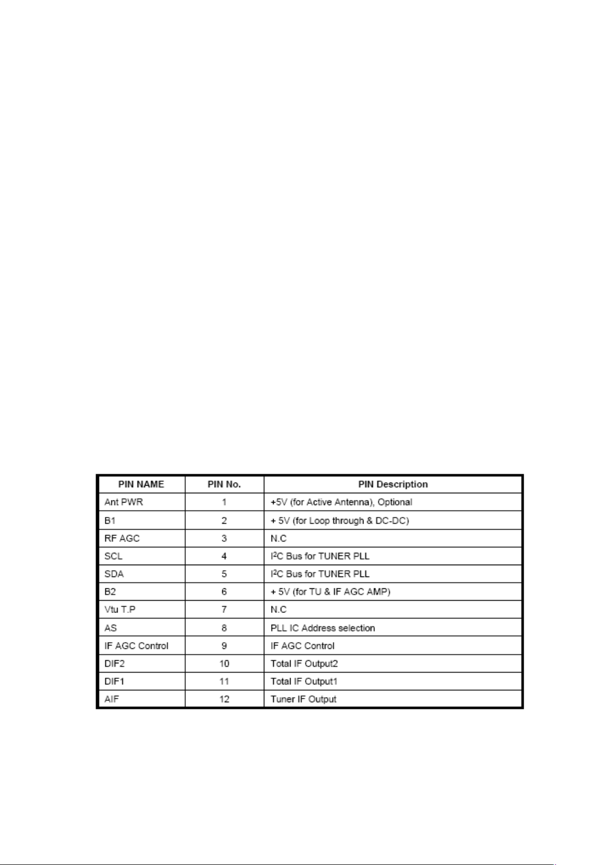
2.3. Pinning:

3. AUDIO AMPLIFIER STAGE WITH MAX9736(8-10WATT)
3.1. General Description
The MAX9736A/B Class D amplifiers provide high-performance,thermally efficient
amplifier solutions. The
into a 4Ω load. The MAX9736B delivers 2 x 6W into 8Ω loads or 1 x 12W into a 4Ω
These devices are pinfor pin compatible, allowing a single audio design to work across a
broad range of platforms, simplifying design efforts, and reducing PCB inventory.
Both devices operate from 8V to 28V and provide a high PSRR, eliminating the need for a
regulated power supply. The MAX9736 offers up to 88% efficiency at 12V supply.
Pin-selectable modulation schemes select between filterless modulation and classic PWM
modulation.
Filterless modulation allows the MAX9736 to pass CE EMI limits with 1m cables using
only a low-cost ferrite bead and capacitor on each output. Classic PWM modulation
is optimized for best audio performance when using a full LC filter.
A pin-selectable stereo/mono mode allows stereo operation
operation into 4Ω loads. In
spare device, allowing flexibility in system design. Comprehensive click-and-pop reduction
circuitry minimizes noise coming into and out of shutdown or mute.
Input op amps allow the user to create summing amplifiers, lowpass or highpass filters,
and select an optimal gain. The MAX9736A/B are available in 32-pin TQFN packages
and specified over the -40°C to +85°C temperature range.
MAX9736A delivers 2 x 15W into 8Ω loads, or 1 x 30W
load.
into 8Ω loads or mono
mono mode, the right input op amp becomes available as a
3.2. Features
Wide 8V to 28V Supply Voltage Range
♦ Spread-Spectrum Modulation Enables Low EMI
Solution
♦ Passes CE EMI Limits with Low-Cost Ferrite
Bead/Capacitor Filter
♦ Low BOM Cost, Pin-for-Pin Compatible Family
♦ High 67dB PSRR at 1kHz Reduces Supply Cost
♦ 88% Efficiency Eliminates Heatsink
♦ Therm
♦ < 1μA Shutdown Mode
♦ Mute Function
♦ Space
Package
al and Output Current Protection
-Saving, 7mm x 7mm x 0.8mm, 32-Pin TQFN
3.3. Applications
LCD/PDP/CRT Monitors
LCD/PDP/CRT TVs
MP3 Docking Stations
Notebook PCs
PC Speakers
All-in-One PCs
3.4. Absolute Ratings
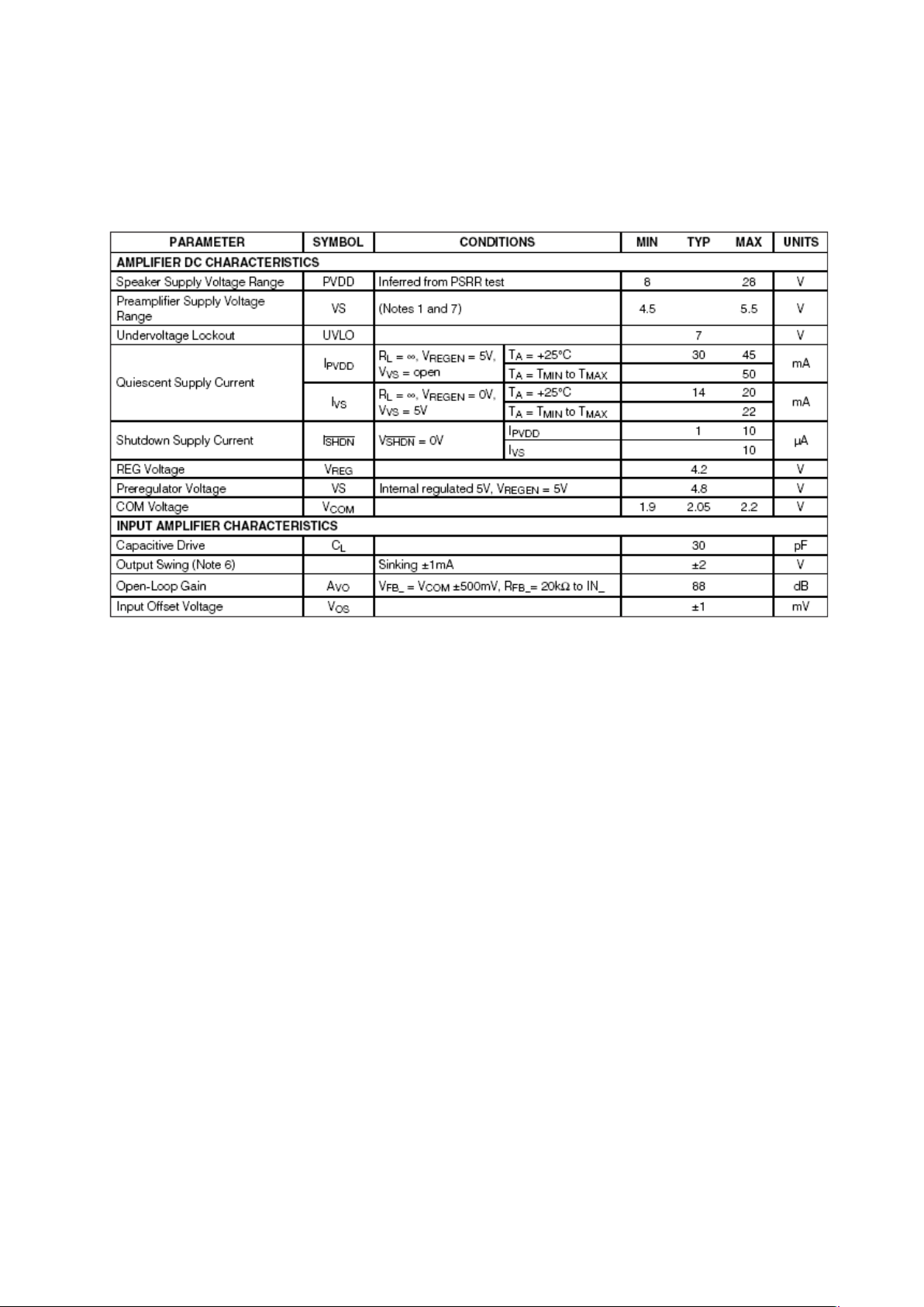
3.4.1. Electrical Characteristics
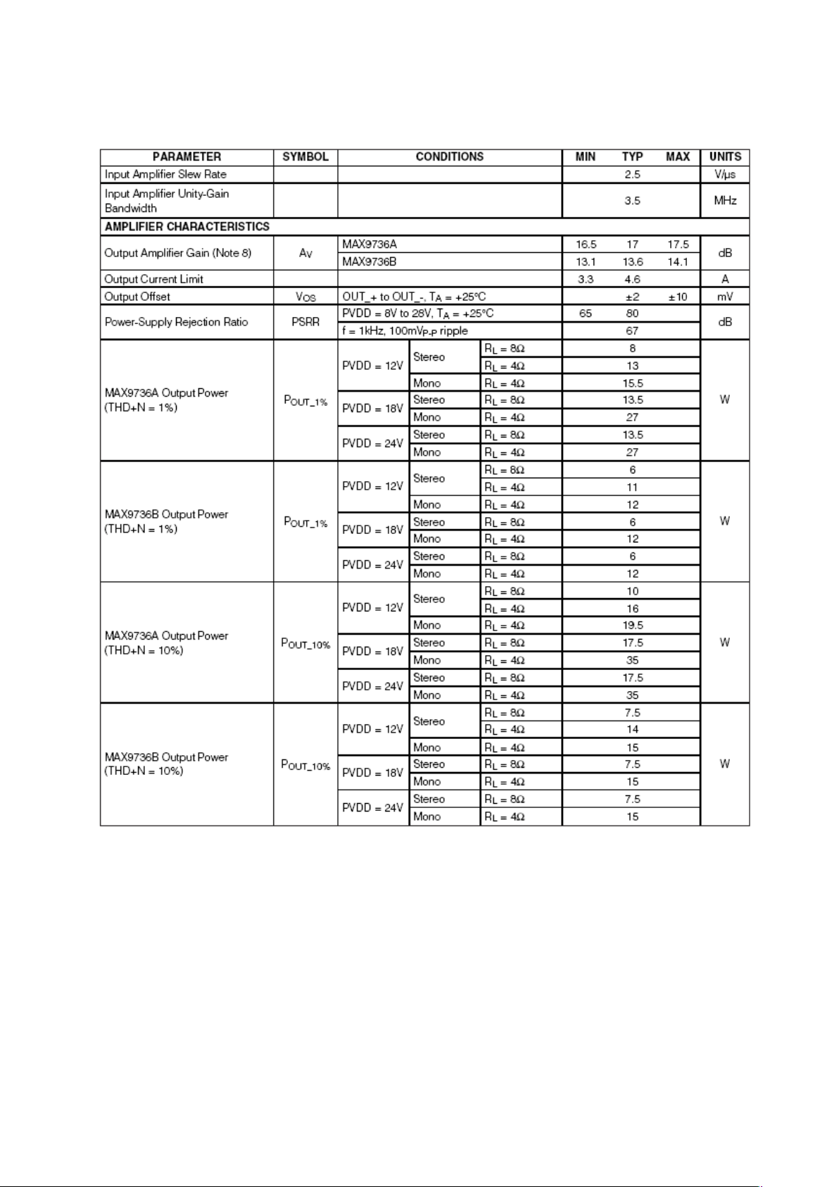
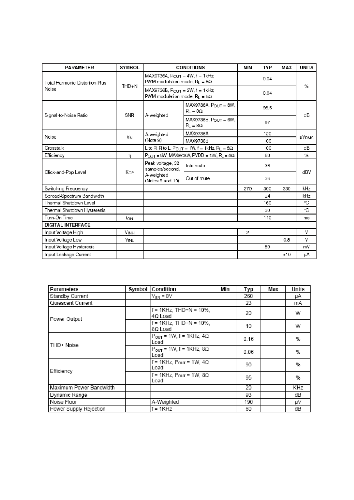
3.4.2. Operating Specifications
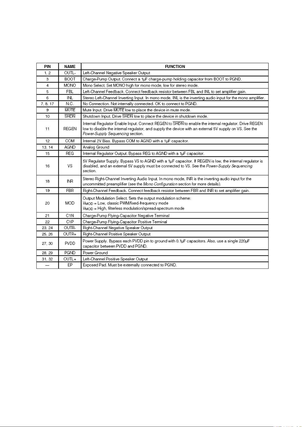
3.5. Pinning
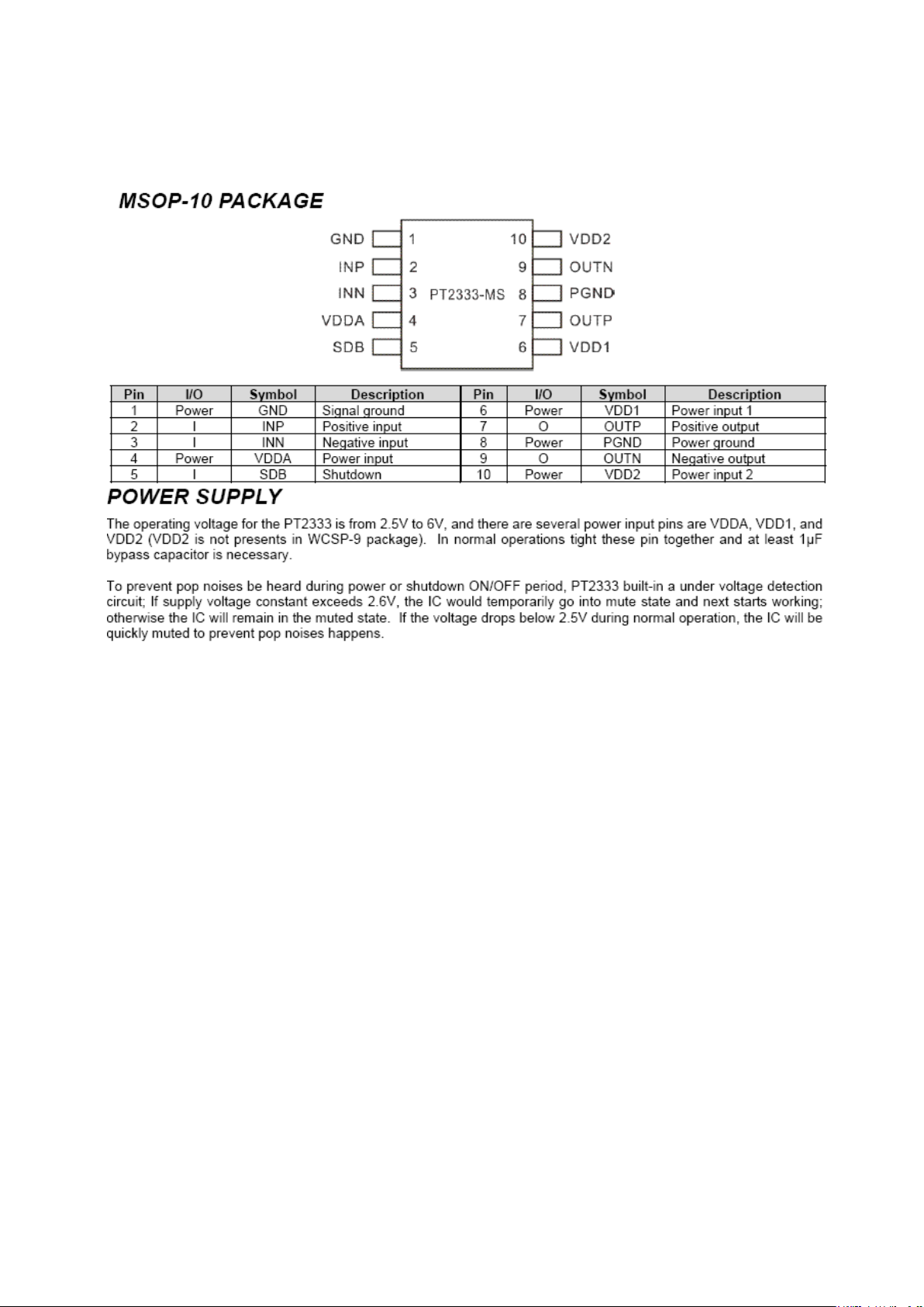
AUDIO AMPLIFIER STAGE WITH PT2333(2.5 WATT)
The PT2333 is a Class-D power amplifier designed for audio equipments, maximum
output power can reach
composed of exclusively designed Class-D circuitry (patented) by PTC, along with
the most advanced semi-conductor technology. When compared to the traditional
Class-AB amplifiers, the PT2333’s has a much higher efficiency (>80%), low
heat dissipation, and produces superior audio quality. PT2333’s external circuitry is
simple and easily accessible, and consists of flawless self-protection capabilities.
The chip’s packaging is small, thus it occupies an insignificant amount of space on
the circuit board; therefore, making it the predominant choice when it comes to
audio amplifiers.
up to 2.5W (VDD=5V, RL=4Ω, THD=10%). The PT2333
Features
CMOS technology
Operating voltage range from 2.7V up to 5.5V
Differential analog input
Maximum output power 2.5W(4Ω) @ THD=10%
Output low-pass LC filter is not required.
Voltage gain determinate by the external resister
Contains shutdown function
POP noises free in shutdown and power ON/OFF
period
Built-in short circuit protection
Built-in overheat protection
High efficiency (8Ω load >85%), low heat
dissipation
Available in MSOP 10-pin and WLCSP 9-pin
miniature packages
Aplications
Cellular phone
Portable media player
GPS
LCD monitor
Small multimedia speakers
Hand-free phone
Laptop
Other audio applications
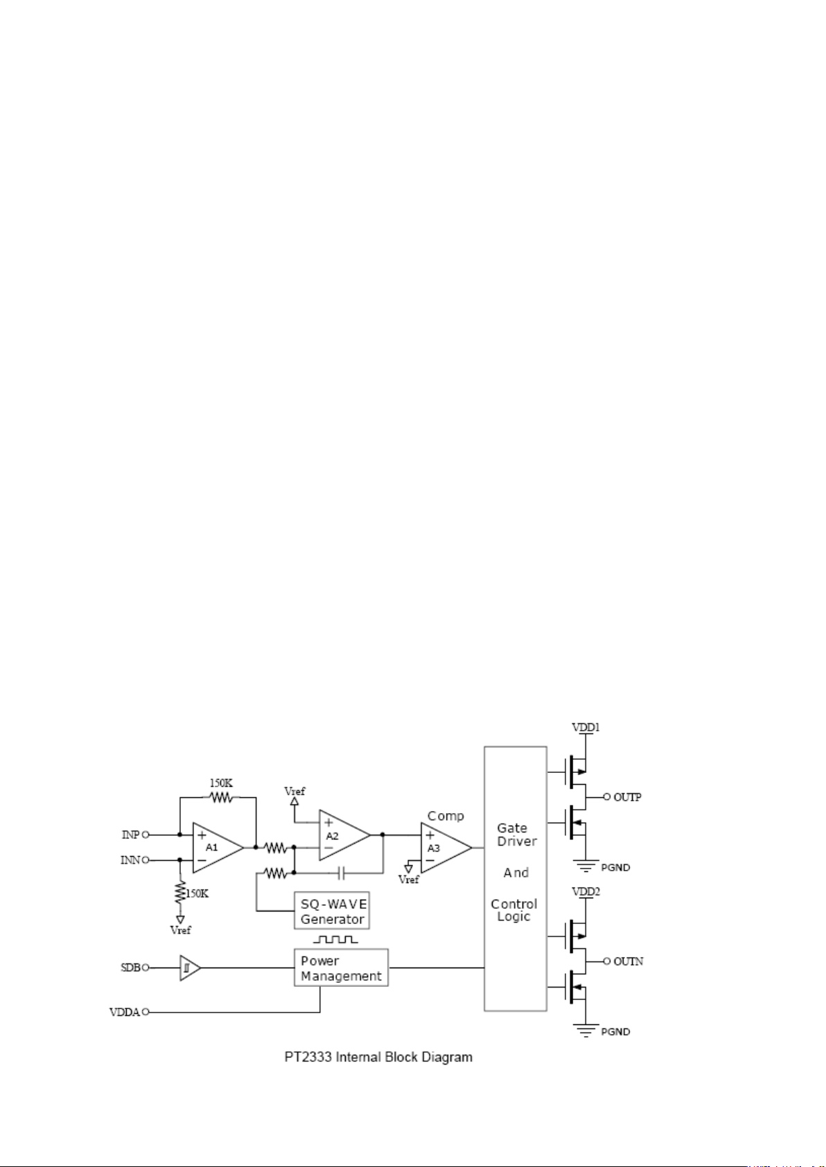
Block Diagram
4. POWER STAGE
The DC voltages required at various parts of the chassis and inverters are provided by a
main power supply unit. The power supply generates 33V, 24V, 12V, 5V, 3,3V and 5V,
3,3V stand by mode DC voltages. Power stage which is on-chasis generates 1,26V stand
by voltage and 8V, 2.5V, 2,6V, 1,8V and 1V supplies for other different parts of the
chassis.
ADAPTOR USE (Optional)
The DC voltages required at various parts of the chassis and inverters are provided by an
external power supply unit or produced on the chassis if an adapter is used for the supply.
The 12V dc voltage is switched by IRF 7314 power mosfet in TV sets with mechanical
switch to produce the required standby voltage. Also regulators and mosfets generate
1.8V, 3.3V and 5V and 1.26V voltages for other different parts of the chassis.

5. MICROCONTROLLER (MSTAR)
Genaral Description
The MST6WB7GQ-3 is a high performance and fully integrated IC for multi-function LCD
monitor/TV with resolutions up to full HD (1920x1080). It is configured with an integrated
triple-ADC/PLL, an integrated DVI/HDCP/HDMI receiver, a multi-standard TV video and audio
decoder, two video de-interlacers, two scaling engines, the MStarACE-3 color engine, an on-screen
display controller, an 8-bit MCU and a built-in output panel interface. By use of external frame
buffer, PIP/POP is provided for multimedia applications. Furthermore, 3-D video decoding and
processing are fulfilled for high-quality TV applications. To further reduce system costs, the
MST6WB7GQ-3 also integrates intelligent power management control capability for greenmode requirements and spread-spectrum support for EMI management.
5.1. Features
LCD TV controller with PIP/POP display functions
Input supports up to UXGA & 1080P
Panel supports up to full HD (1920x1080)
TV decoder with 3-D comb filter
Multi-standard TV sound demodulator and decoder
10-bit triple-ADC for TV and RGB/YPbPr
10-bit video data processing
Integrated DVI/HDCP/HDMI compliant receiver
High-quality dual scaling engines & dual 3-D video de-interlacers
3-D video noise reduction
Full function PIP/PBP/POP
MStarACE-3 picture/color processing engine
Embedded On-Screen Display (OSD) controler engine
Built-in MCU supports PWM & GPIO
Built-in dual-link 8/10-bit LVDS transmitter
5-volt tolerant inputs
Low EMI and power saving features
296-pin LQFP
NTSC/PAL/SECAM Video Decoder
Supports NTSC M, NTSC-J, NTSC-4.43, PAL (B,D,G,H,M,N,I,Nc), and SECAM
Automatic TV standard detection
Motion adaptive 3-D comb filter for NTSC/PAL
8 configurable CVBS & Y/C S-video inputs
Supports Teletext level-1.5, WSS, VPS, Closed-caption, and V-chip
Macrovision detection
CVBS video output

Video IF for Multi-Standard Analog TV
Digital low IF architecture
Stepped-gain PGA with 26 dB tuning range and 1 dB tuning resolution
Maximum IF analog gain of 37dB in addition to digital gain
Programmable TOP to accommodate different tuner gain to optimize noise and linearity
performance
Multi-Standard TV Sound Decoder
Supports BTSC/NICAM/A2/EIA-J demodulation and decoding
FM stereo & SAP demodulation
L/Rx4, mono, and SIF audio inputs
L/Rx3 loudspeaker and line outputs
Supports sub-woofer output
Built-in audio output DAC’s
Audio processing for loudspeaker channel, including volume, balance, mute, tone, EQ, and
virtual stereo/surround
Optional advanced surround available (Dolby1, SRS2, BBE3… etc)
Digital Audio Interface
I2S digital audio input & output
S/PDIF digital audio input & output
HDMI audio channel processing capability
Programmable delay for audio/video synchronization
Analog RGB Compliant Input Ports
Three analog ports support up to UXGA
Supports HDTV RGB/YPbPr/YCbCr
Supports Composite Sync and SOG (Sync-on-Green) separator
Automatic color calibration
DVI/HDCP/HDMI Compliant Input Port
Two HDMI input ports with built-in switch
Supports TMDS clock up to 225MHz @ 1080P 60Hz with 12-bit deep-color resolution
Single link on-chip DVI 1.0 compliant receiver
High-bandwidth Digital Content Protection(HDCP) 1.1 compliant receiver
6. MPEG-2/MPEG-4 DVB Decoder (STi7101)
6.1. General Description
The STi7101 is a new generation, high-definition IDTV / set-top box / DVD decoder chip, and
provides very high performance for low-cost HD systems. STx7101 includes an H.264 video
decoder for new, low bit rate applications. Based on the Omega2 (STBus) architecture, this
system-on-chip is a full back-end processor for digital terrestrial, satellite, cable, DSL and IP

client high-definition set-top boxes, compliant with ATSC, DVB, DIRECTV, DCII,
OpenCable and ARIB BS4 specifications. It includes all processing for DVD applications.
The STx7101 demultiplexes, decrypts and decodes HD or SD video streams with associated
multi-channel audio. Video is output to two independently formatted displays: a full resolution
display intended for a TV monitor, and a downsampled display intended for a VCR or DVD-R.
Connection to a TV or display panel can be analog through the DACs, or digital through a copy
protected DVI/HDMI. Composite outputs are provided for connection to the VCR with
Macrovision protection. Audio is output with optional PCM mixing to an S/PDIF interface,
PCM interface, or through integrated stereo audio DACs. Digitized analog programs can also
be input to the STx7101 for reformatting and display. The STx7101 includes a graphics
rendering and display capability with a 2D graphics accelerator, three graphics planes and a
cursor plane. A dual display compositor provides mixing of graphics and video with
independent composition for each of the TV and VCR/DVD-R outputs. The STx7101 includes
a stream merger to allow seven different transport streams from different sources to be merged
and processed concurrently. Applications include DVR time-shifted viewing of a terrestrial
program, while acquiring an EPG/data stream from a satellite or cable front end.
The flexible descrambling engine is compatible with required standards including DVB, DES,
AES and Multi2. The STx7101 embeds a 266 MHz ST40-202 CPU for applications and device
control. A dual DDR1 SDRAM memory interface is used for higher performance, to allow the
video decoder the required memory bandwidth for HD H.264 and sufficient bandwidth for the
CPU and the rest of the system. A second memory bus is also provided for flash memory,
storing resident software, and for connection of peripherals. This bus also has a high speed
synchronous mode that can be used to exchange data between two STx7101 devices. This can
be used to connect a second STx7101 as a co-decoder for a dual TV STB application. A harddisk drive (HDD) can be connected either to the serial ATA interface, or as an expansion drive
through the USB 2.0 port.
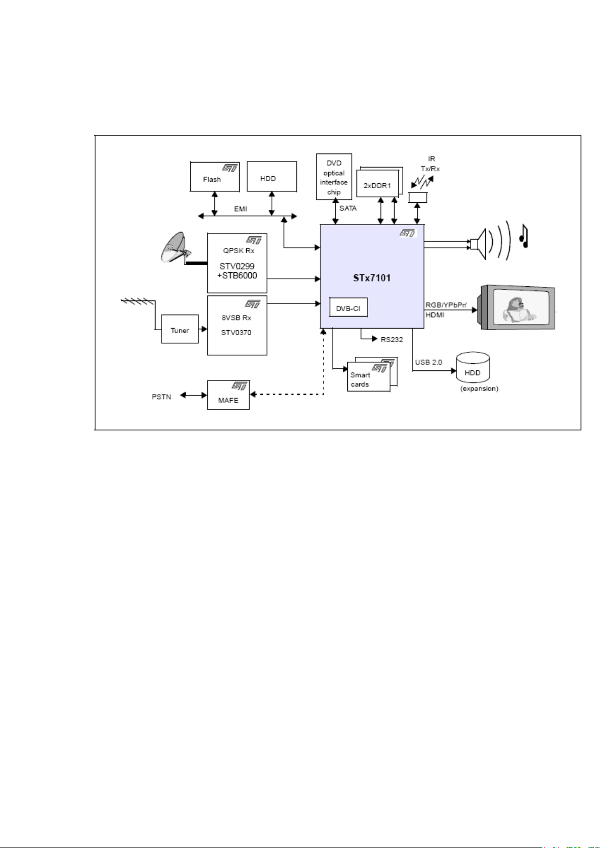
The figure below shows the architecture of the Sti7101.
6.2 Features
The STx7101 is a single-chip, high definition video decoder including:
_ H.264 support
_ Linux® and OS21 compatible ST40 CPU core: 266 MHz
_ transport filtering and descrambling
_ video decoder: H.264 (MPEG-4 part 10) and MPEG-2
_ SVP compliant
_ graphics engine and dual display: standard and highdefinition
_ audio decoder
_ DVD data retrieval and decryption
The STx7101 also features the following embedded interfaces:
_ USB 2.0 host controller/PHY interface
_ DVI/HDMI™ output
_ digital audio and video auxiliary inputs
_ low-cost modem
_ 100BT ethernet controller with integrated MAC and MII/ RMII interface for external PHY
_ serial ATA (SATA)

Processor subsystem
_ ST40 32-bit superscaler RISC CPU
_ 266 MHz, 2-way set associative 16-Kbyte ICache, 32-Kbyte DCache, MMU
_ 5-stage pipeline, delayed branch support
_ floating point unit, matrix operation support
_ debug port, interrupt controller
Transport subsystem
_ TS merger/router
_ 2 serial/parallel inputs
_ 1 bidirectional interface
_ merging of 3 external transport streams
_ transport streams from memory support
_ NRSS-A module interface
_ TS routing for DVB-CI and CableCARD
modules
_ Programmable transport interfaces (PTIs)
_ two programmable transport interfaces
_ two transport stream demultiplexers: DVB, DIRECTV®, ATSC, ARIB, OpenCable, DCII
_ integrated DES, AES, DVB and Multi2 descramblers
_ NDS random access scrambled stream protocol (RASP) compliant
_ NDS ICAM CA
_ support for VGS, Passage and DVS042 residue handling
Video/graphics subsystem
_ H.264(MPEG-4 part 10) main and high profile level 4.1/MPEG-2 MP@HL video decoder
_ advanced error concealment and trick mode support
_ dual MPEG-2 MP@HL decode
_ SD digital video input
_ Displays
_ one HD display multi format capable (1080I, 720P, 480P/576P, 480I/576I)
analog HD output RGB or YPbPr
HDMI encoded output
_ one standard-definition display
analog SD output: YPbPr or YC and CVBS
_ Gamma 2D/3D graphics processor
_ triple source 2D gamma blitter engine
_ alpha blending and logical operations
_ color space and format conversion
_ fast color fill
_ arbitrary resizing with high quality filters
_ acceleration of direct drawing by CPU
_ Gamma compositor and video processor
_ 7-channel mixer for high definition output
_ independent 2-channel mixer for SD output
_ 3 graphic display planes
_ high-quality video scaler

_ motion and detail adaptive deinterlacer
_ linear resizing and format conversions
_ horizontal and vertical filtering
_ Copy protection
_ HDMI /HDCP copy protection hardware
_ SVP compliant
_ Macrovision® copy protection for 480I, 480P, 576I, 576P outputs
_ DTCP-IP
_ AWG-based DCS analog copy protection
Audio subsystem
_ Digital audio decoder
_ support for all the most popular audio standards including MPEG-1 layer I/II, MPEG-2 layer
II, MPEG-2 AAC, MPEG- 4 AAC LC 2-channel/5.1 channel MPEG-4 AAC+SBR 2channel/5.1 channel, Dolby® Digital EX, Pro Logic® II, MLP™ and DTS®
_ PCM mixing with internal or external source and sample rate conversion
_ 6- to 2-channel downmixing
_ PCM audio input
_ independent multichannel PCM output, S/PDIF output and analog output
_ Stereo 24-bit audio DAC for analog output
_ IEC958/IEC1937 digital audio output interface (S/PDIF)
_ CSS/CPxM copy protection hardware Interfaces
_ External memory interface (EMI)
_ 16-bit interface supporting ROM, flash, SFlash, SRAM, peripherals
_ access in 5 banks
_ high speed synchronous mode for interconnecting two STx7101 devices
_ External microprocessor interface (EMPI)
_ 32-bit MPX satellite, target-only interface,
_ synchronous operation at MPX clock speed, capable of 100 MHz,
_ Dual local memory interface (LMI)
_ dual interface (2 x 32-bit) for DDR1 200-MHz (DDR400) memories,
supports 128-, 256- and 512-Mbit devices
_ USB 2.0 host controller/PHY interface
_ Serial ATA hard-disk drive support
_ record and playback with trick modes
_ pause and time shifting, watch and record
_ 100BT Ethernet controller, MAC and MII/RMII
_ On-chip peripherals
_ 4 ASCs (UARTs) with Tx and Rx FIFOS, two of which can be used in smartcard interfaces
_ 2 smartcard interfaces and clock generators (improved to reduce external circuitry)
_ 3 SSCs for I²C/SPI master slaves interfaces
_ serial communications interface (SCIF)
_ 2 PWM outputs
_ teletext serializer and DMA module
_ 6 banks of general purpose I/O, 3.3 V tolerant
_ SiLabs line-side (DAA) interface
_ modem analog front end (MAFE) interface
_ infrared transmitter/receiver supporting RC5, RC6 and RECS80 codes
_ UHF remote receiver input interface
_ interrupt level controller and external interrupts, 3.3 V tolerant
_ low power/RTC/watchdog controller
_ integrated VCXO
_ DiSEqC 2.0 interface
_ PWM capture/compare functions
_ Flexible multi-channel DMA Services and package
_ JTAG/TAP interface, ST40 toolset support, ST231 toolset support
_ Package
_ 35 x 35 PBGA, 580 + 100 balls (standard version)
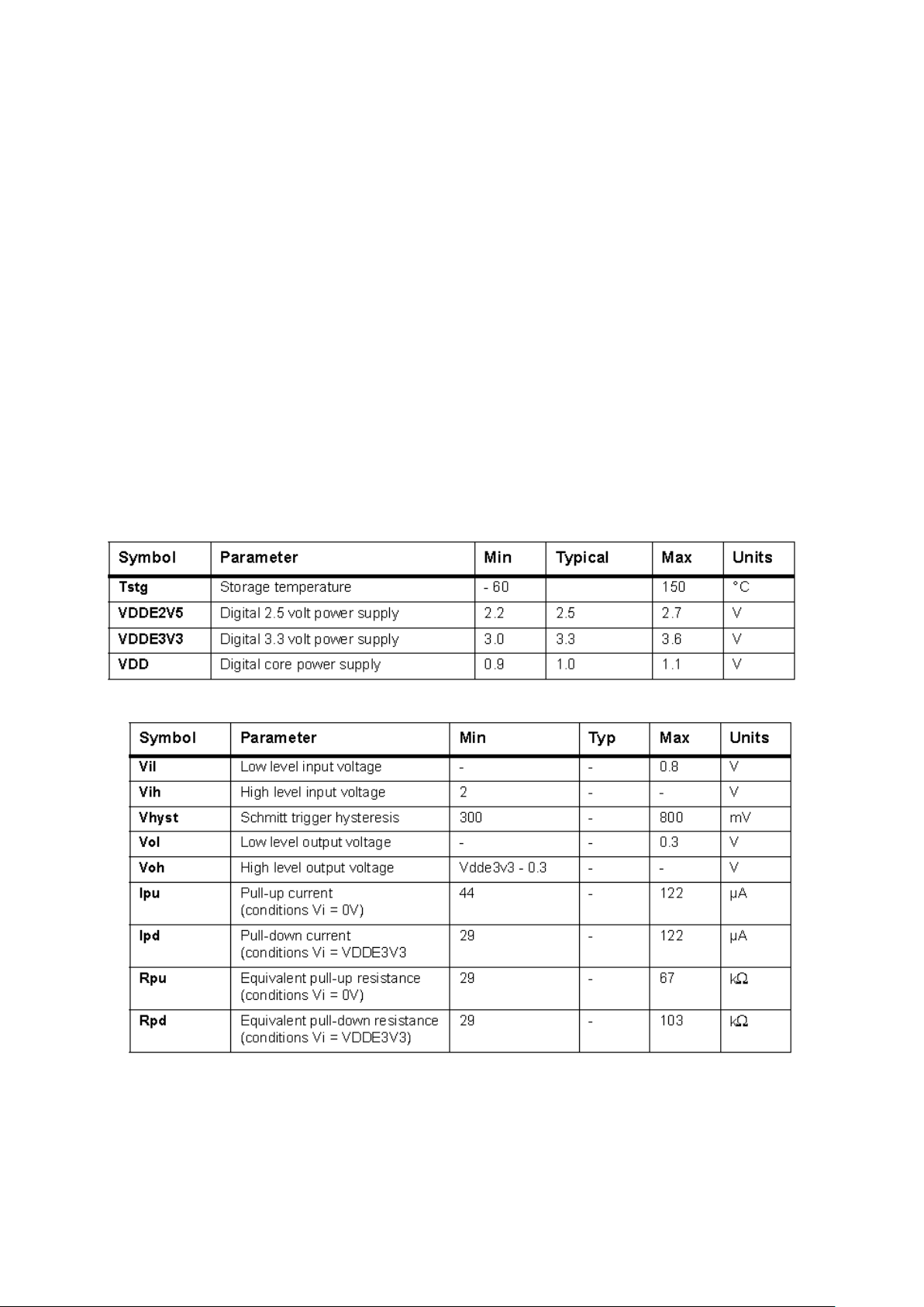
6.3 Absolute Maximum Ratings
I/O specifications 3.3 volt pads

I/O specifications 2.5 volt pads
1
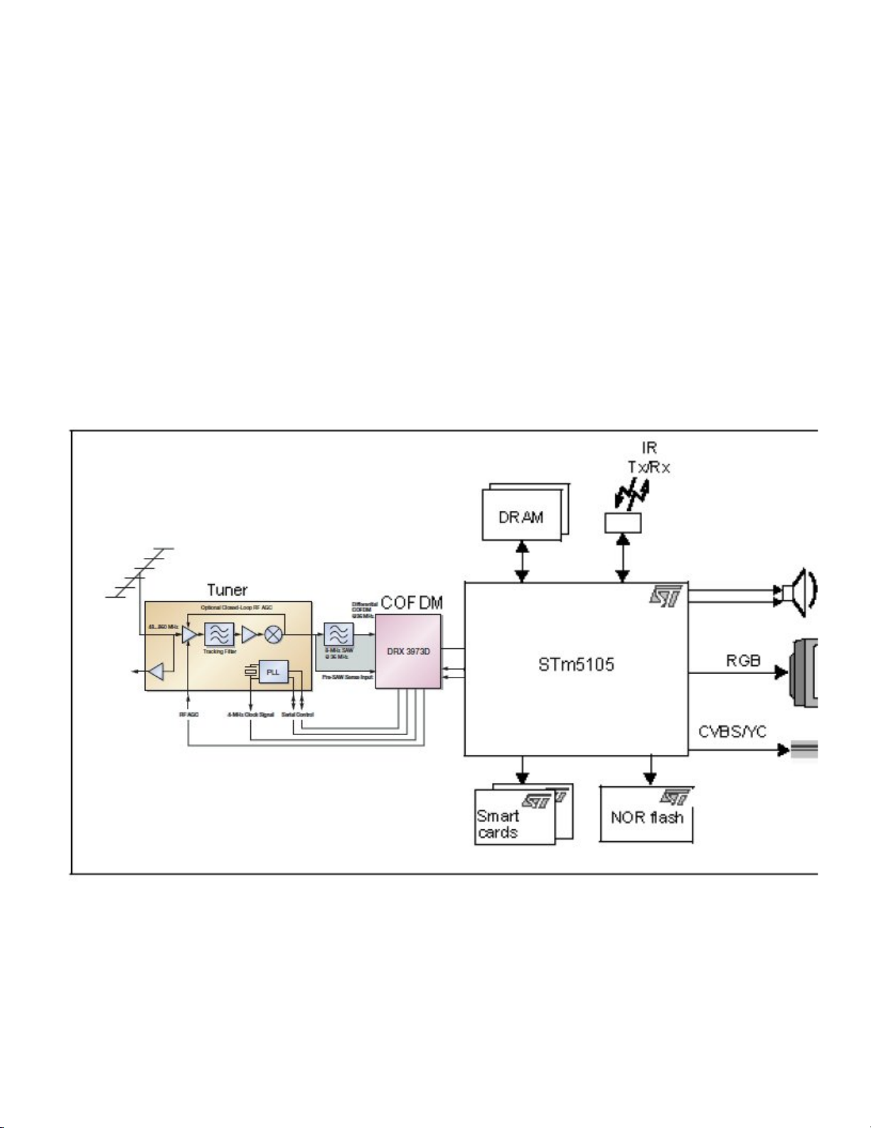
7 – DVB-T Demodulator (COFDM) DRX3973D
7.1 General description:
The DRX 3973D is the fourth-generation COFDM demodulator that offer today’s highest level of front-end integration
resulting in ultimate DVB-T digital reception, compliant to ETS 300 744, DTG D-Book, EICTA E-Book, and Nordig Unified
v1.0.2 .
The DRX 3973D applies cutting-edge digital filtering techniques in combination with a high-performance A/D-converter
and PLL configuration, resulting in
superior performance figures in the presence of digital and analog adjacent channels.
Progressive channel estimator algorithms provide exceptional performance in multipath- and dynamicecho conditions –
an especially important feature for single-frequency networks and indoor reception.
The state-of-the-art impulsive noise cruncher suppresses interferences originating from sources such as cars, electrical
motors, and household appliances.
7.2 Features
– Highest level of front-end integration and flexibility: • Integrated PGA (programmable gain amplifier) 30 dB
• Single 8 MHz SAW filter operation
• 2 AGC control signals available for RF and IF amplifier control
• Flexible clock reference options
• Re-use of 4 MHz tuner clock reference
• Pre-SAW sense input for optimal RF AGC setting and RF-level measurement
– Excellent digital reception performance:
2
• Superior digital and analog adjacent channel performance (> 40dB for QEF)
• Impulsive noise cruncher
• Multipath and dynamic echoes
– The input IF frequency ranging up to 44 MHz ensures upward compatibility for new tuner topologies
– Integrated microprocessor to perform autonomous detection and operation of all possible DVB-T modes, without
interaction with the host processor
– Fully automatic and fast signal acquisition: UHF and VHF band-scan in <20 seconds
– Meets all international DVB-T receiver specifications: Nordig Unified, DTG, EICTA
– Comfortable software drivers for integration of tuner and COFDM demodulator
– Secondary serial interface for tuner control
– 5 V tolerant AGC and secondary serial protocol outputs
– 2 general purpose I/O pins (GPIO)
– Configurable parallel or serial MPEG-TS output
– PMQFP64-2 package: footprint 10
10 mm (DRX 3973D)
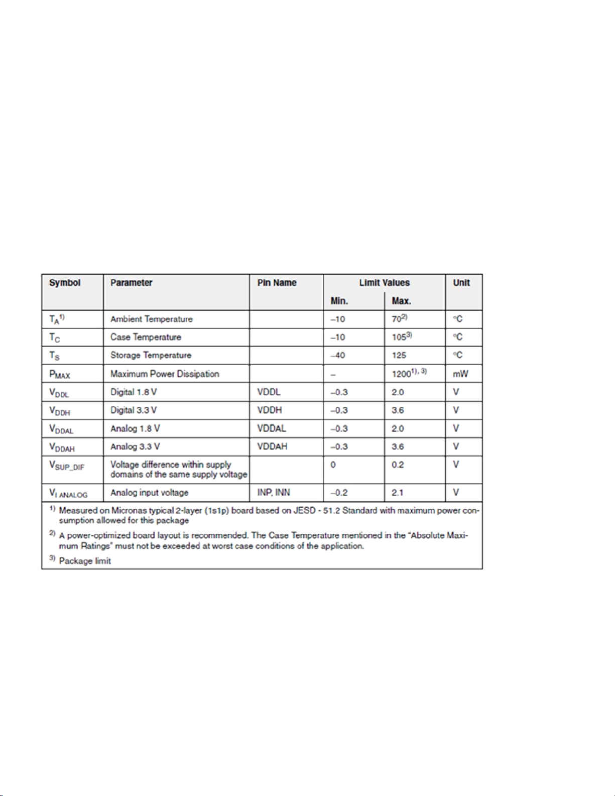
7.3 Absolute Maximum Ratings
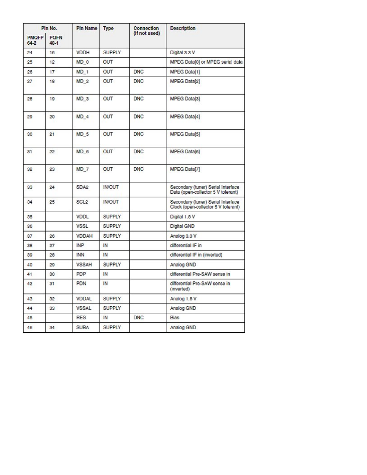
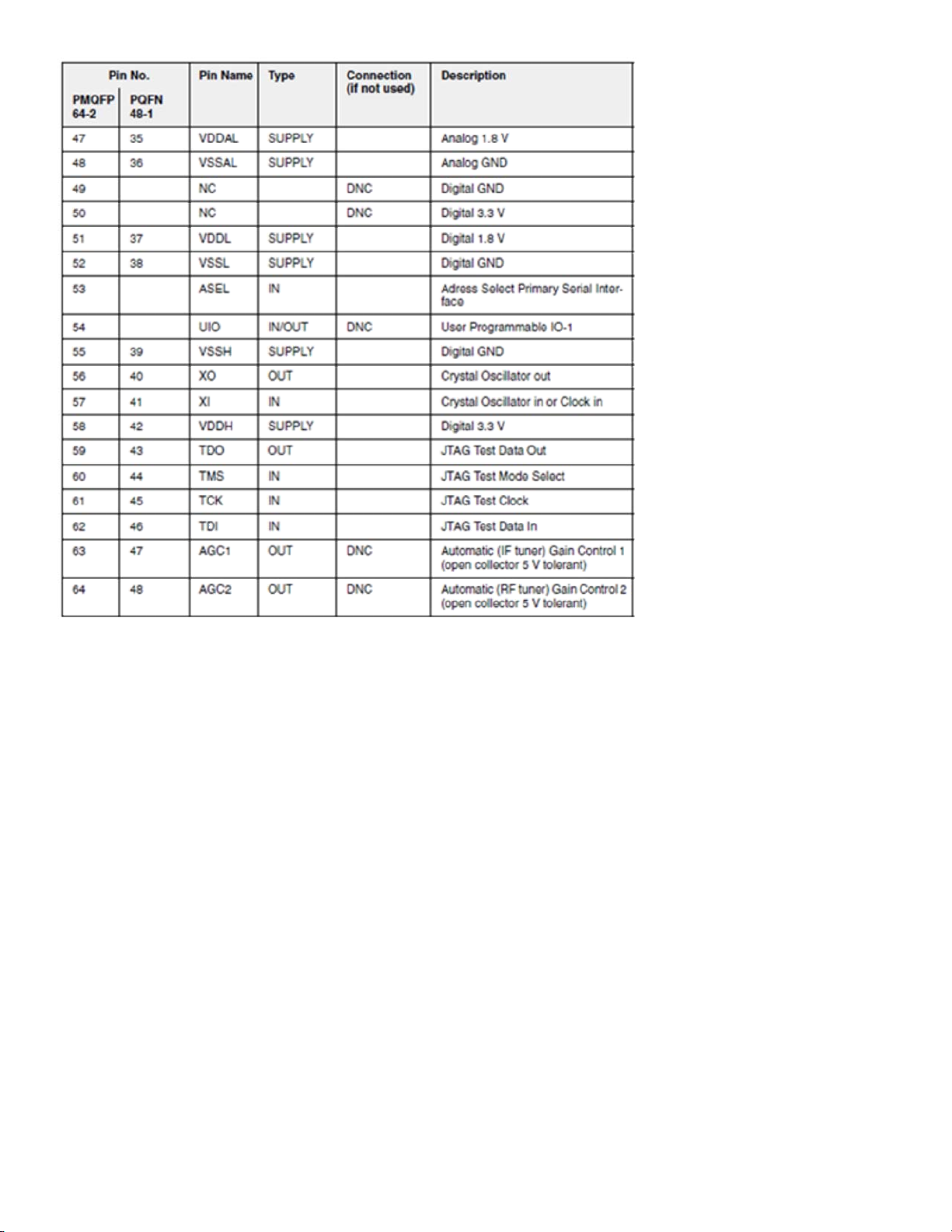
7.4 Pin description:
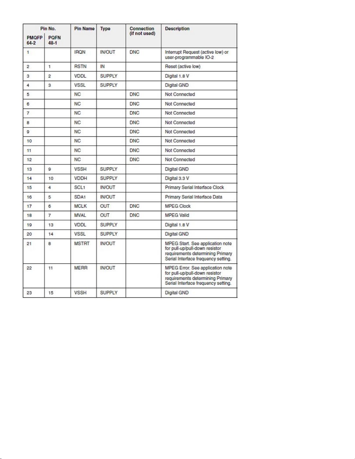
345

8 DVB-C DEMODULATOR – STV0297E
8.1 General Desription
The STV0297E is a complete single-chip QAM (quadrature amplitude modulation)
demodulation and FEC (forward error correction) solution that performs sampled IF to
transport stream (MPEG-2 or MPEG-4) block processing of QAM signals. It is intended for
the digital transmission of compressed television, sound, and data services over cable. It
is fully compliant with ITU-T J83 Annexes A/C or DVB-C specification bitstreams (ETS
300 429, “Digital broadcasting systems for television, sound and data services – Framing
structure, channel coding and modulation - Cable Systems”). It can handle square (16,
64, 256-QAM) and non-square (32, 128-QAM) constellations. Japanese DBS systems
require a transport stream multiplex frame (TSMF) layer to carry digital signals over cable
systems. When the recovered transport stream is a multiplex frame, the STV0297E postprocesses it to extract a single transport stream. Automatic detection of the TSMF layer is
provided. The chip integrates an analog-to-digital converter that delivers the required
performance to handle up to 256-QAM signals in a direct IF sampling architecture, thus
eliminating the need for external downconversion.
8.2 Features
Decodes ITU-T J.83-Annexes A/C and DVB-C bit streams
Processes Japanese transport stream multiplex frame (TSMF)
High-performance integrated A/D converter suitable for direct IF architecture in all
QAM (quadrature amplitude modulation) modes
Supports 16, 32, 64, 128 and 256 point constellations
Small footprint package: (10 x 10 mm²)
Very low power consumption
Full digital demodulation
Variable symbol rates
Front derotator for better low symbol rate performance and relaxed tuner
constraints
Integrated matched filtering
Robust integrated adaptive pre and post equalizer
On-chip FEC A/C with ability to bypass individual blocks
10 programmable GPIO
Two AGC outputs suitable for delayed AGC applications (sigma-delta outputs)
Integrated signal quality monitors, plus lock indicator and interrupt function mapped
to GPIO pin
Improved signal acquisition
System clock generated on-chip from quartz crystal
Low frequency crystal operations 4, 16, 25 - 30 MHz
4 I2C addresses
Easy control and monitoring via 2-wire fast I2C bus

8.3 Absolute Maximum Ratings
8.4 Pinning

9 HY5DV281622DT-5 DDR SDRAM 128M
9.1 General Description
The Hynix HY5DV281622 is a 134,217,728-bit CMOS Double Data Rate(DDR)
Synchronous DRAM, ideally suited for the point-to-point applications which requires high
bandwidth. The Hynix 8Mx16 DDR SDRAMs offer fully synchronous operations
referenced to both rising and falling edges of the clock. While all addresses and control
inputs are latched on the rising edges of the CK (falling edges of the /CK), Data,Data
strobes and Write data masks inputs are sampled on both rising and falling edges of it.
The data paths are internally pipelined and 2-bit prefetched to achieve very high
bandwidth. All input and output voltage levels are compatible with SSTL_2.
9.2 Features
3.3V for VDD and 2.5V for VDDQ power supply
All inputs and outputs are compatible with SSTL_2 interface
JEDEC standard 400mil 66pin TSOP-II with 0.65mm pin pitch
Fully differential clock inputs (CK, /CK) operation
Double data rate interface
Source synchronous - data transaction aligned to bidirectional data strobe (DQS)
x16 device has 2 bytewide data strobes (LDQS, UDQS) per each x8 I/O
Data outputs on DQS edges when read (edged DQ) Data inputs on DQS centers
when write (centered DQ)
Data(DQ) and Write masks(DM) latched on the both rising and falling edges of the
data strobe
All addresses and control inputs except Data, Data strobes and Data masks
latched on the rising edges of the clock
Write mask byte controls by LDM and UDM
Programmable /CAS latency 3 / 4 supported
Programmable Burst Length 2 / 4 / 8 with both sequential and interleave mode
Internal 4 bank operations with single pulsed /RAS
tRAS Lock-Out function supported
Auto refresh and self refresh supported
4096 refresh cycles / 32ms
Full, Half and Matched Impedance(Weak) strength driver option controlled by
EMRS
 Loading...