

Vestel 17MB30, 17MB30-1 Service Manual

TABLE OF CONTENTS
1. INTRODUCTION................................................................................................................... 5
2. TUNER.................................................................................................................................... 5
2.1. General description of UV1316: ................................................................................. 5
2.2. Features of UV1316: ................................................................................................... 5
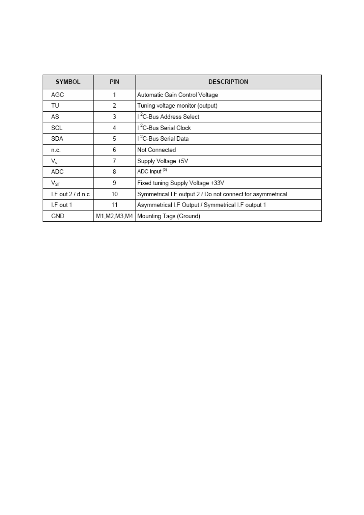
2.3. Pinning: ....................................................................................................................... 6
3. AUDIO AMPLIFIER STAGE WITH TDA8933 ................................................................... 6
3.1. General Description..................................................................................................... 6
3.2. Features ....................................................................................................................... 6
3.3. Applications ................................................................................................................ 7
3.4. Absolute Ratings ......................................................................................................... 7
3.4.1. Performance figures SE........................................................................................... 7
3.4.2. Performance figures BTL........................................................................................ 8
3.5. Pinning ........................................................................................................................ 9
4. POWER STAGE ..................................................................................................................... 9
5. MICROCONTROLLER (MSTAR)........................................................................................ 9
5.1. General Descripction................................................................................................... 9
5.2. General Features........................................................................................................ 10
5.3. Port Allocation .......................................................................................................... 13
5.4. ELECTRICAL PECIFICATIONS.......................................................................... 26
6. TDA 9886 I2C-bus controlled single/multistandard alignment-free IF PLL....................... 27
6.1. General Desription .................................................................................................... 27
6.2. Features ..................................................................................................................... 27
6.3. Absolute Maximum Ratings...................................................................................... 28
6.4. Pinning ...................................................................................................................... 28
7. SERIAL 32K I2C EEPROM................................................................................................. 29
7.1. General Description................................................................................................... 29
7.2. Features ..................................................................................................................... 29
7.3. Absolute Maximum Ratings...................................................................................... 29
7.4. Pinning ...................................................................................................................... 30
8. CLASS AB STEREO HEADPHONE DRIVER TDA1308 ................................................. 30
8.1. General Description................................................................................................... 30
8.2. Features ..................................................................................................................... 30
8.3. Pinning ...................................................................................................................... 31
9. SAW FILTER ....................................................................................................................... 31
9.1. IF Filter for Audio Applications – Epcos K9656M .................................................. 31
9.1.1. Standart: ................................................................................................................ 31
9.1.2. Features: ................................................................................................................ 31
9.1.3. Pin configuration:.................................................................................................. 31
9.1.4. Frequency response:.............................................................................................. 32
9.2. IF Filter for Video Applications – Epcos K9658M................................................... 33
9.2.1. Standart: ................................................................................................................ 33
9.2.2. Features: ................................................................................................................ 33
9.2.3. Frequency response:.............................................................................................. 33
10. 8M x 16 DDR Synchronous DRAM (SDRAM) ............................................................... 35
10.1. General Description............................................................................................... 35
10.2. Features ................................................................................................................. 35
10.3. Absolute Maximum Ratings.................................................................................. 36
10.4. Pinning .................................................................................................................. 38
11. Low On-Resistance Wideband/Video Quad 2-Channel Mux/DeMux - PI5V330 ............ 40
11.1. General Description............................................................................................... 40

11.2. Features ................................................................................................................. 40
11.3 Absolute Maximum Ratings...................................................................................... 40
11.4 Pinning ...................................................................................................................... 41
12. Low voltage mono/stereo power Amplifier - TDA7050T ................................................ 42
12.1. General Description............................................................................................... 42
12.2. Features ................................................................................................................. 42
11.3 Absolute Maximum Ratings...................................................................................... 42
13. Mbit Uniform Sector, Serial Flash Memory ..................................................................... 43
13.1 General Description................................................................................................... 43
13.2 Features ..................................................................................................................... 43
13.3 Absolute Maximum Ratings...................................................................................... 44
13.4 Pinning ...................................................................................................................... 46
14. IC DESCRIPTIONS AND INTERNAL BLOCK DIAGRAM ........................................ 46
14.1. LM1117................................................................................................................. 46
14.1.1. General Description............................................................................................... 46
14.1.2. Features ................................................................................................................. 47
14.1.3. Applications .......................................................................................................... 47
14.1.4. Absolute Maximum Ratings.................................................................................. 47
14.1.5. Pinning .................................................................................................................. 47
14.2. MP1593 ................................................................................................................. 48
14.2.1. General Description............................................................................................... 48
14.2.2. Features ................................................................................................................. 48
14.2.3. Applications .......................................................................................................... 48
14.2.4. Absolute Maximum Ratings.................................................................................. 48
14.2.5. Electrical Characteristics....................................................................................... 49
14.2.6. Pinning .................................................................................................................. 49
14.3. FDC642P............................................................................................................... 50
14.3.1. General Description............................................................................................... 50
14.3.2. Features ................................................................................................................. 50
14.3.3. Absolute Maximum Ratings.................................................................................. 50
14.3.4. Pinning .................................................................................................................. 50
14.4. 24LC02.................................................................................................................. 51
14.4.1. General Description............................................................................................... 51
14.4.2. Features ................................................................................................................. 51
14.4.3. Pinning .................................................................................................................. 51
14.5. µPA672T ............................................................................................................... 52
14.5.1. General Description............................................................................................... 52
14.5.2. Features ................................................................................................................. 52
14.5.3. Absolute Maximum Ratings.................................................................................. 52
14.5.4. Pinning .................................................................................................................. 52
14.6. M74HC4052.......................................................................................................... 53
14.6.1. General Description............................................................................................... 53
14.6.2. Features ................................................................................................................. 53
14.6.3. Absolute Maximum Ratings.................................................................................. 53
14.6.4. Pinning .................................................................................................................. 53
14.7. Max810.................................................................................................................. 54
14.7.1. General Description............................................................................................... 54
14.7.2. Features ................................................................................................................. 54
14.7.3. Absolute Maximum Ratings.................................................................................. 55
14.7.4. Pinning .................................................................................................................. 55
14.8. 24LC21.................................................................................................................. 56

14.8.1. General Description............................................................................................... 56
14.8.2. Features ................................................................................................................. 56
14.8.3. Absolute Maximum Ratings.................................................................................. 56
14.8.4. Pinning .................................................................................................................. 57
15. SERVICE MENU SETTINGS.......................................................................................... 57
15.1. Video Setup ........................................................................................................... 57
15.2. AudioSetup............................................................................................................ 58
15.3. Service Scan/Tuning Setup ................................................................................... 59
15.4. Options .................................................................................................................. 60
15.5. External Source Settings ....................................................................................... 61
15.6. Select Language .................................................................................................... 62
15.7. Preset ..................................................................................................................... 62
15.8. NVM Edit.............................................................................................................. 63
15.9. Programming......................................................................................................... 63
15.10. Diagnostic.............................................................................................................. 63
16. SOFTWARE UPDATE DESCRIPTION.......................................................................... 63
16.1 17MB30 Analog Part Software Update Procedure .................................................. 63
16.2 17MB30 HDCP key upload procedure. ................................................................... 64
16.3 17MB30 HDMI EDID key upload procedure.......................................................... 64
17. BLOCK DIAGRAMS ....................................................................................................... 66
17.1. General Block Diagram......................................................................................... 66
17.2. Power Management............................................................................................... 67
17.3. IF Demodulator Block Diagram............................................................................ 69
17.4. MSTAR General Block Diagram.......................................................................... 70

1. INTRODUCTION
17MB30 Main Board consists of MSTAR consept. This IC is capable of handling Audio
processing, video processing, Scaling-Display processing, 3D comb filter, OSD and text
processing, 8 bit dual LVDS transmitter.
TV supports PAL, SECAM, NTSC colour standards and multiple transmission standards
as B/G, D/K, I/I’, and L/L’ including German and NICAM stereo.
Sound system output is supplying 2x3W (10%THD) for stereo 4
Supported peripherals are:
1 RF input VHF1, VHF3, UHF @ 75Ohm
1 Side AV (SVHS, CVBS, HP, R/L_Audio)
2 SCART sockets
1 YPbPr
1 PC input
2 HDMI input
1 Stereo audio input for PC
1 Line out
1 Subwoofer out
1 SPDIF output
Ω speakers.
2. TUNER
A vertical mounted tuner is used in the product, which is suitable for CCIR + CATV
channel (3 bant) systems B/G, H, L/ L’, I/I’, and D/K. The tuning is available through the
digitally controlled I2C bus (PLL). Below you will find info on the Tuner in use.
2.1. General description of UV1316:
Lgtuner is designed to meet a wide range of applications. It is a combined VHF, UHF
tuner suitable for CCIR+ CATV channel (3 bant) systems B/G, H, L, L’, I and I’. The low
IF output impedance has been designed for direct drive of a wide variety of SAW filters
with sufficient suppression of triple transient.
2.2. Features of UV1316:
small sized UHF/VHF tuners
Systems CCIR: B/G, H, L, L’, I and I’; OIRT: D/K
Digitally controlled (PLL) tuning via I2C-bus
Off-air channels, S-cable channels and Hyper band
Compact size
Complies with the requirements of radiation, signal handling capability and
immunity conforming to European standards “CENELEC EN55020” and
“EN55013”.
2.3. Pinning:
3. AUDIO AMPLIFIER STAGE WITH TDA8933
3.1. General Description
17MB30 uses a Switched Mode Amplifier (SMA) for audio, based on the TDA8933
device of Philips Semiconductors operating from an asymmetrical supply. TDA8933 can
be used in either a stereo SE configuration or a mono BTL configuration. These features
enable an engineer to design a high performance, reliable and cost effective Switch
Mode Amplifier (SMA) with only a small number of external components.
3.2. Features
• High efficiency Class-D audio amplifier due to a low RDS_ON
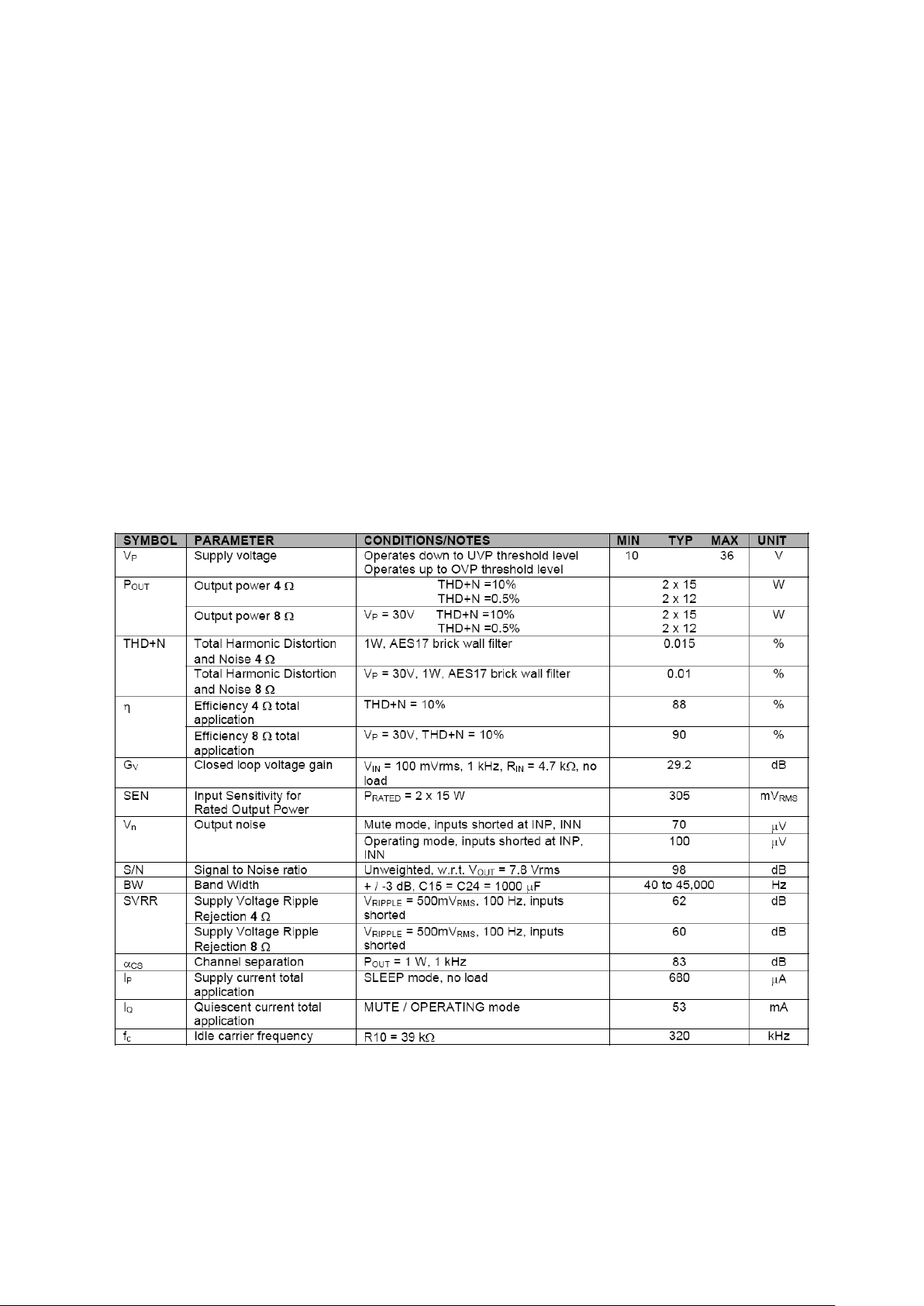
• Operates from a wide voltage range 10 V to 36 V (asymmetrical) or +/-5 V to +/-18 V
(symmetrical)
• Maximum power capability:
• TDA8932 is 2 x 25 WRMS maximum in 4
• TDA8933 is 2 x 15 WRMS maximum in 8
• Cycle-by-cycle current limiting to avoid interruption during normal operation
• Unique Thermal Foldback (TF) to avoid interruption during normal operation
• Integrated Half Supply Voltage (HVP) buffers for reference and SE output capacitance
(asymmetrical supply)
• Internal logic for pop-free power supply on/off cycling
• Low standby-current in SLEEP-mode for power saving regulations
• Window Protection (WP)
• Under Voltage Protection (UVP)
• Over Voltage Protection (OVP)
Ω SE without heat sink
Ω SE without heat sink
• UnBalance Protection (UBP)
• Over Current Protection (OCP)
• Over Temperature Protection (OTP)
3.3. Applications
The TDA8933 Class-D amplifier is intended for:
Flat-TV application
Flat panel monitors
Multimedia systems
Wireless speakers
Micro systems
3.4. Absolute Ratings
3.4.1. Performance figures SE
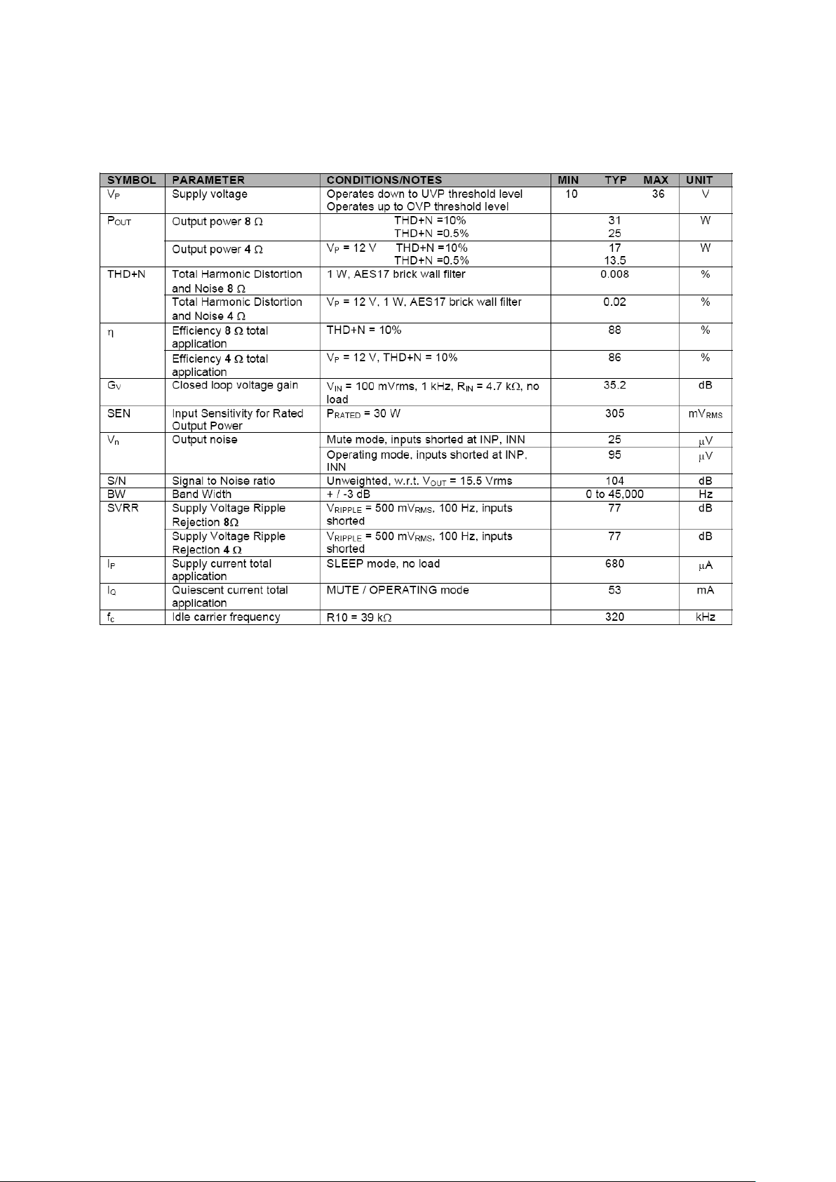
3.4.2. Performance figures BTL
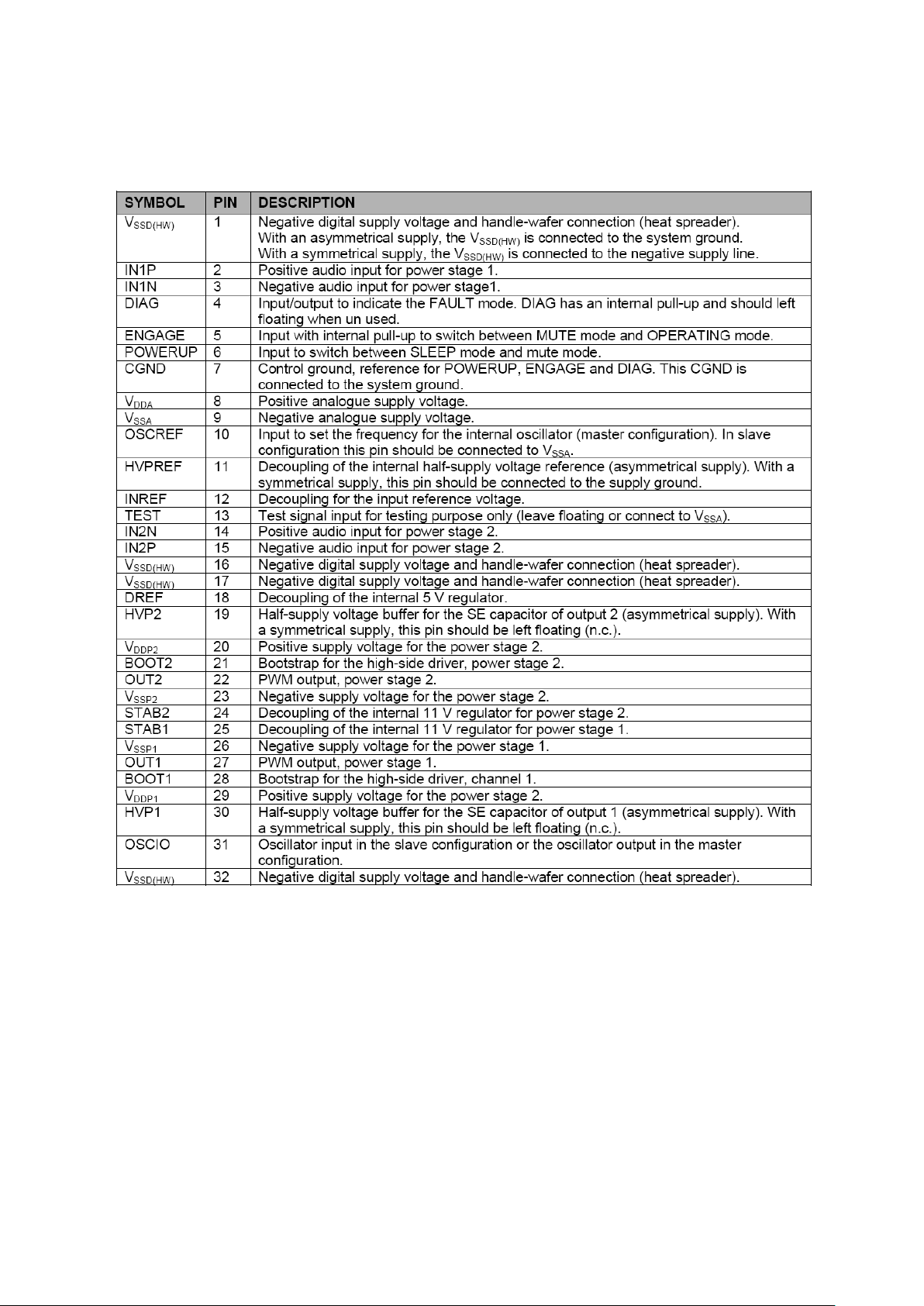
3.5. Pinning
4. POWER STAGE
The DC voltages required at various parts of the chassis and inverters are provided by a
main power supply unit and power interface board. IPS generates 12V and 5V DC
supply. Power stage which is on-chasis generates +12V for audio amplifier, 1.2V and
3.3V stand by voltage and 33V, 12V, 5V and 3.3Vsupplies for other different parts of the
chassis.
5. MICROCONTROLLER (MSTAR)
5.1. General Descripction
The MST6W82BL is a high performance and fully integrated IC for multi-function LCD
monitor/TV with resolutions up to SXGA/WXGA+. It is configured with an integrated

triple-ADC/PLL, an integrated DVI/HDCP/HDMI receiver Note, a multi-standard TV
video and audio decoder, two video de-interlacers, two scaling engines, the MStarACE3 color engine, an on-screen display controller, an 8-bit MCU and a built-in
output panel interface. By use of external frame buffer, PIP/POP is provided for
multimedia applications. Furthermore, 3-D video decoding and processing are fulfilled
for high-quality TV applications. To further reduce system costs, the MST6W82BL also
integrates intelligent power management control capability for green-mode requirements
and spread-spectrum support for EMI management. Note: The optional HDMI function is
available with MST6W82BLD.
LCD TV controller with PIP/POP display functions
Input supports up to SXGA & 1080P
Panel supports up to SXGA/WXGA+
TV decoder with 3-D comb filter
Multi-Standard TV sound demodulator and decoder
10-bit triple-ADC for TV and RGB/YPbPr
10-bit video data processing
Integrated DVI/HDCP/HDMI compliant receiver Note 1
High-quality scaling engine & 3-D video de-interlacer
Full function PIP/PBP/POP
MStarACE-3 picture/color processing engine
Embedded On-screen display controller (OSD) engine
Built-in MCU supports PWM & GPIO
Built-in dual-link 8-bit LVDS transmitter
5 Volt tolerant inputs
Low EMI and power saving features
256-pin LQFP
5.2. General Features
NTSC/PAL/SECAM Video Decoder
Supports NTSC M, NTSC-J, NTSC-4.43, PAL (B,D,G,H,M,N,I,Nc), and SECAM
Automatic TV standard detection
Motion adaptive 3-D comb filter for NTSC/PAL
8 configurable CVBS & Y/C S-video inputs
Supports Teletext level-1.5, WSS, VPS, Closed-caption, and V-chip
Macrovision detection
CVBS video output
Multi-Standard TV Sound Decoder
Supports BTSC/NICAM/A2/EIA-J demodulation and decoding
FM stereo & SAP demodulation
L/Rx4, mono, and SIFx2 audio input
L/Rx3 loudspeaker and line output
Supports sub-woofer output
Built-in audio output DAC’s
Audio processing for loudspeaker channel, including volume, balance, mute,
tone, EQ, and virtual stereo/surround
Supports advanced surround (Dolby1, SRS2, BBE3… etc) Note 2

1 Trademark of Dolby Laboratories
2 Trademark of SRS Labs, Inc.
3 Registered trademark of BBE Sound, Inc.
Digital Audio Interface
I2S digital audio input & output
S/PDIF digital audio input & output
HDMI audio channel processing capability Note 1
Programmable delay for audio/video synchronization
Analog RGB Compliant Input Ports
Three analog ports support up to 150MHz
Supports PC RGB input up to SXGA@75Hz
Fast blanking and function selection switch support full SCART functions
Supports HDTV RGB/YPbPr/YCbCr up to 1080P
Supports Composite Sync and SOG (Sync-on-Green) separator
Automatic color calibration
DVI/HDCP/HDMI Compliant Input Port Note 1
Two HDMI input ports with built-in switch
Operates up to 150 MHz (up to SXGA @75Hz)
Single link on-chip DVI 1.0 compliant receiver
High-bandwidth Digital Content Protection
(HDCP) 1.1 compliant receiver
High Definition Multimedia Interface (HDMI) 1.2 compliant receiver
Long-cable tolerant robust receiving
Support HDTV up to 1080P
Auto-Configuration/Auto-Detection
Auto input signal format and mode detection
Auto-tuning function including phasing, positioning, offset, gain, and jitter
detection
Sync Detection for H/V Sync
Digital Video Input
One 4:2:2 ITU-R BT.656 8/10-bit digital video input port
One 4:2:2 ITU-R BT.601 16-bit digital video input port
High-Performance Scaling Engine
Fully Programmable shrink/zoom capabilities
Nonlinear video scaling supports various modes including Panorama
Video Processing & Conversion
3-D motion adaptive video deinterlacers
Edge-oriented adaptive algorithm for smooth low-angle edges
Automatic 3:2 pull-down & 2:2 pull-down detection and recovery
PIP/PBP/POP with programmable size and location, supports multi-video
applications

MStar 3rd Generation Advanced Color Engine (MStarACE-3) automatic picture
enhancement gives:
Brilliant and fresh color
Intensified contrast and details
Vivid skin tone
Sharp edge
Enhanced depth of field perception
Accurate and independent color control
sRGB compliance allows end-user to experience the same colors as viewed on
CRTs and other displays
Programmable 12-bit RGB gamma CLUT
3-D video noise reduction
Frame rate conversion supports 120Hz panels
On-Screen OSD Controller
16/256 color palette
256/512 1-bit/pixel font
128/256 4-bit/pixel font
Supports texture function
Supports 4K attribute/code
Horizontal and vertical stretch of OSD menus
Pattern generator for production test
Supports OSD MUX and alpha blending capability
Supports blinking and scrolling for closed caption applications
8-bit LVDS/TTL Panel Interface
Supports dual link LVDS up to SXGA@75Hz or WXGA@120Hz
Supports 8-bit single TTL panel
Supports 2 data output formats: Thine & TI data mappings
Compatible with TIA/EIA
With 6/8 bits options
Reduced swing for LVDS for low EMI
Supports flexible spread spectrum frequency with 360Hz~11.8MHz and up to
25% modulation
Integrated Micro Controller
Embedded 8032 micro controller
Configurable PWM’s and GPIO’s
Low-speed ADC inputs for system control
SPI bus for external flash
Supports external MCU option controlled through 4-wire double-data-rate direct
MCU bus or 8-bit direct MCU bus
External Connection/Component
16-bit data bus for external frame buffer (SDR or DDR DRAM)
All system clocks synthesized from a single external clock
Note:
1. The optional HDMI function is available with
MST6W82BLD.
2. Please see Ordering Guide for details on advanced
surround.

6. TDA 9886 I2C-bus controlled single/multistandard
alignment-free IF PLL
6.1. General Desription
The TDA9886 is an alignment-free multistandard (PAL,SECAM and NTSC) vision and
sound IF signal PLL demodulator for positive and negative modulation including sound
AM and FM processing.
6.2. Features
5 V supply voltage
Gain controlled wide-band Vision Intermediate Frequency (VIF) amplifier (AC-
coupled)
Multistandard true synchronous demodulation with active carrier regeneration
(very linear demodulation, good intermodulation figures, reduced harmonics,
excellent pulse response)
Gated phase detector for L/L accent standard
Fully integrated VIF Voltage Controlled Oscillator (VCO), alignment-free;
frequencies switchable for all negative and positive modulated standards via I2Cbus
Digital acquisition help, VIF frequencies of 33.4, 33.9, 38.0, 38.9, 45.75 and
58.75 MHz
4 MHz reference frequency input [signal from Phase-Locked Loop (PLL) tuning
system] or operating as crystal oscillator
VIF Automatic Gain Control (AGC) detector for gain control, operating as peak
sync detector for negative modulated signals and as a peak white detector for
positive modulated signals
Precise fully digital Automatic Frequency Control (AFC) detector with 4-bit digital-
to-analog converter; AFC bits via I2C-bus readable
TakeOver Point (TOP) adjustable via I2C-bus or alternatively with potentiometer
Fully integrated sound carrier trap for 4.5, 5.5, 6.0 and 6.5 MHz, controlled by
FM-PLL oscillator
Sound IF (SIF) input for single reference Quasi Split Sound (QSS) mode (PLL
controlled)
SIF AGC for gain controlled SIF amplifier; single reference QSS mixer able to
operate in high performance single reference QSS mode and in intercarrier
mode, switchable via I2C-bus
AM demodulator without extra reference circuit
Alignment-free selective FM-PLL demodulator with high linearity and low noise
I2C-bus control for all functions
I2C-bus transceiver with pin programmable Module Address (MAD).
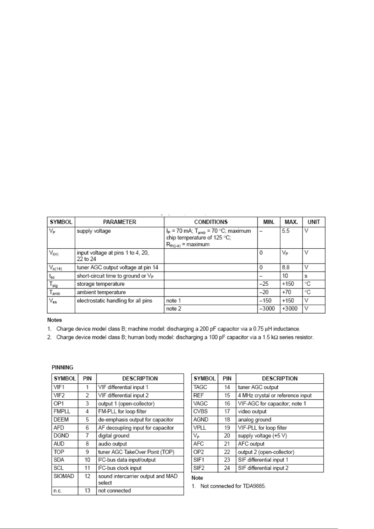
6.3. Absolute Maximum Ratings
6.4. Pinning
7. SERIAL 32K I2C EEPROM
7.1. General Description
The M24C32 devices is I2C-compatible electrically erasable programmable memories
(EEPROM). İt is organized as 4096 × 8 bits.
7.2. Features
Two-Wire I2C serial interface Supports 400kHz Protocol
Single supply voltages
– 2.5 to 5.5V
– 1.8 to 5.5V
– 1.7 to 5.5V
Write Control Input
Byte and Page Write
Random And Sequential Read modes
Self-Timed programming cycle
Automatic address incrementing
Enhanced ESD/Latch-Up Protection
More than 1 Million Write cycles
More than 40-year data retention
Packages – ECOPACK® (RoHS compliant)
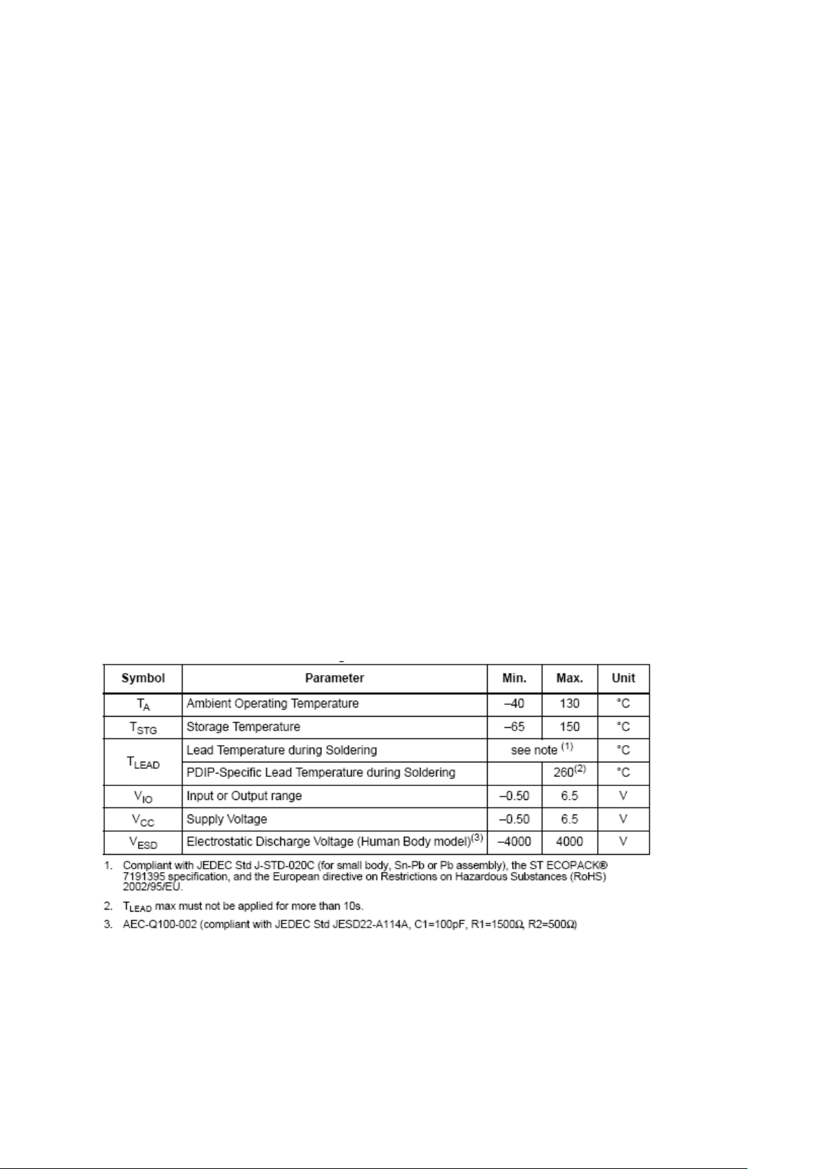
7.3. Absolute Maximum Ratings
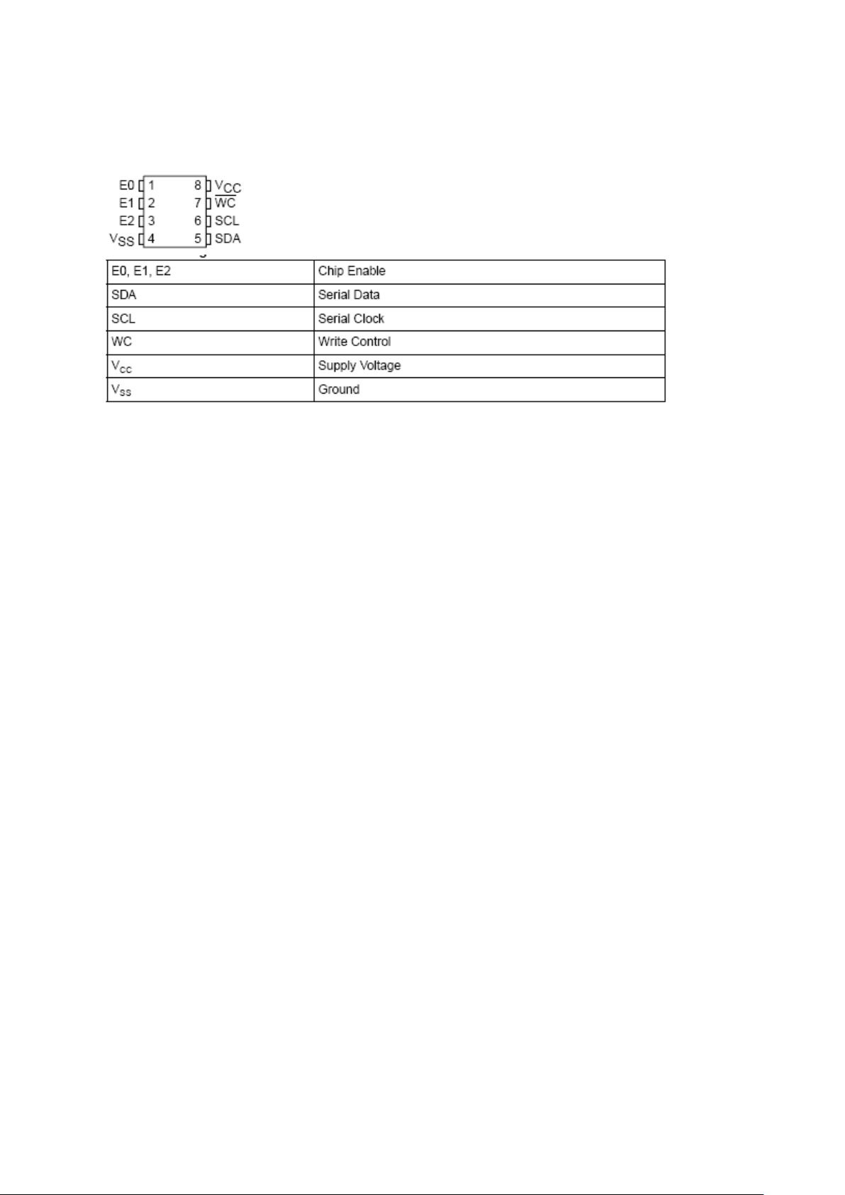
7.4. Pinning
8. CLASS AB STEREO HEADPHONE DRIVER TDA1308
8.1. General Description
The TDA1308 is an integrated class AB stereo headphone driver contained in an SO8
or a DIP8 plastic package. The device is fabricated in a 1 mm CMOS process and has
been primarily developed for portable digital audio applications. It gets its input from two
analog audio outputs (DACA_L and DACA_R) of MSP 34x0G. The gain of the output is
adjustable by the feedback resistor between the inputs and outputs.
8.2. Features
Wide temperature range
No switch ON/OFF clicks
Excellent power supply ripple rejection
Low power consumption
Short-circuit resistant
High performance
High signal-to-noise ratio
High slew rate
Low distortion
Large output voltage swing.
Power supply maximum 60 mW to 32Ω (THD<0.1%)
5V single supply
SNR 110 dB
Power supply ripple rejection
Typically 3 mA supply current at no load
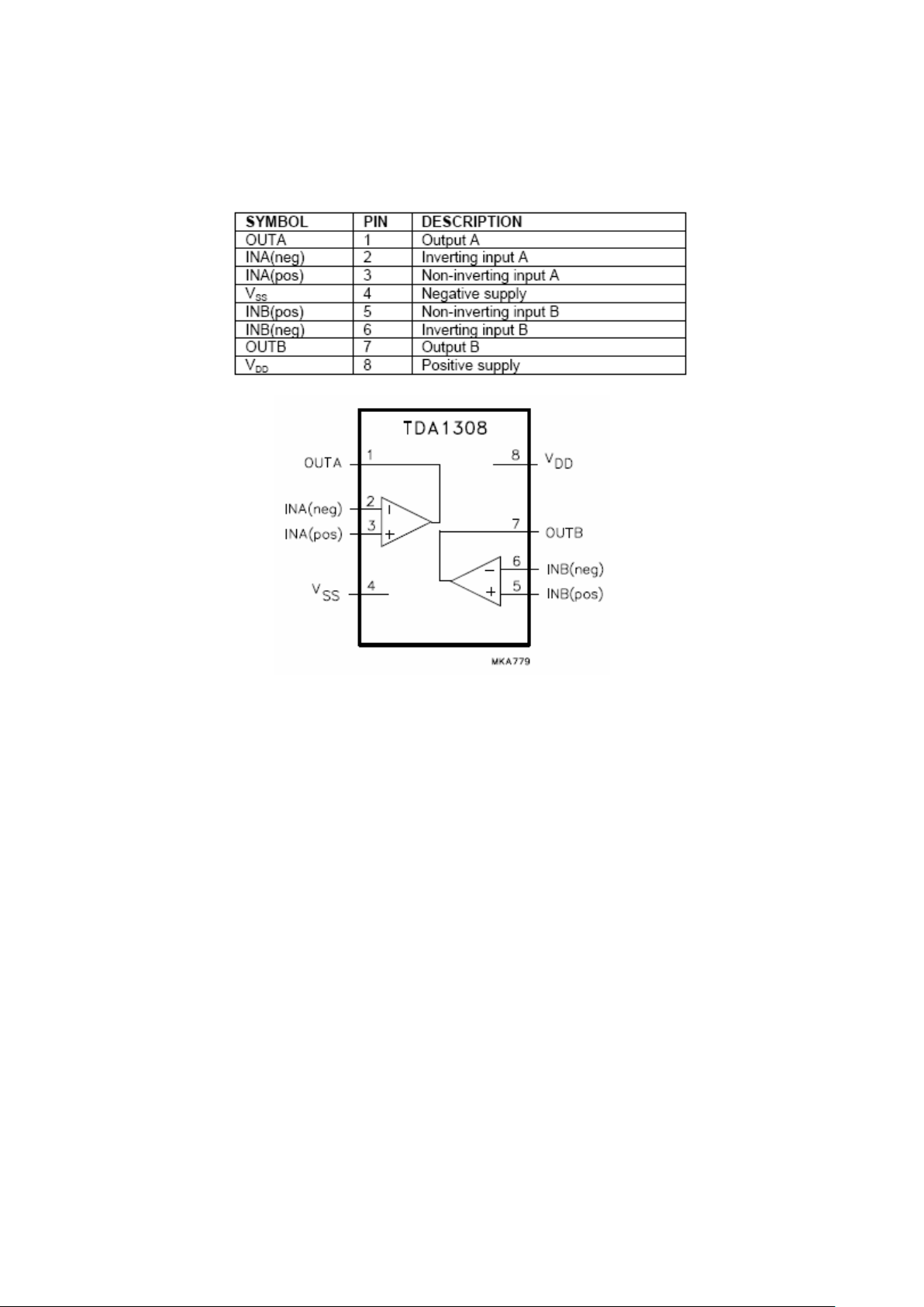
8.3. Pinning
9. SAW FILTER
9.1. IF Filter for Audio Applications – Epcos K9656M
9.1.1. Standart:
B/G
D/K
I
L/L’
9.1.2. Features:
TV IF audio filter with two channels
Channel 1 (L’) with one pass band for sound carriers at 40,40 MHz (L’) and 39,75
MHz (L’- NICAM)
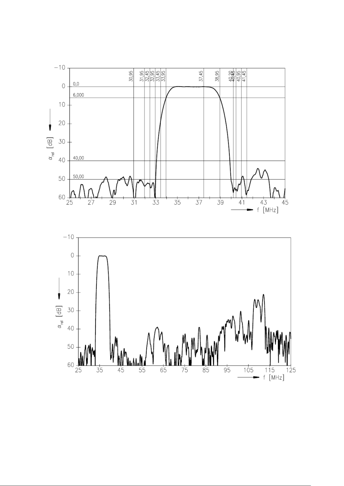
Channel 2 (B/G,D/K,L,I) with one pass band for sound carriers between 32,35
MHz and 33,40 MHz
9.1.3. Pin configuration:
1 Input
2 Switching input
3 Chip carrier - ground
4 Output
5 Output
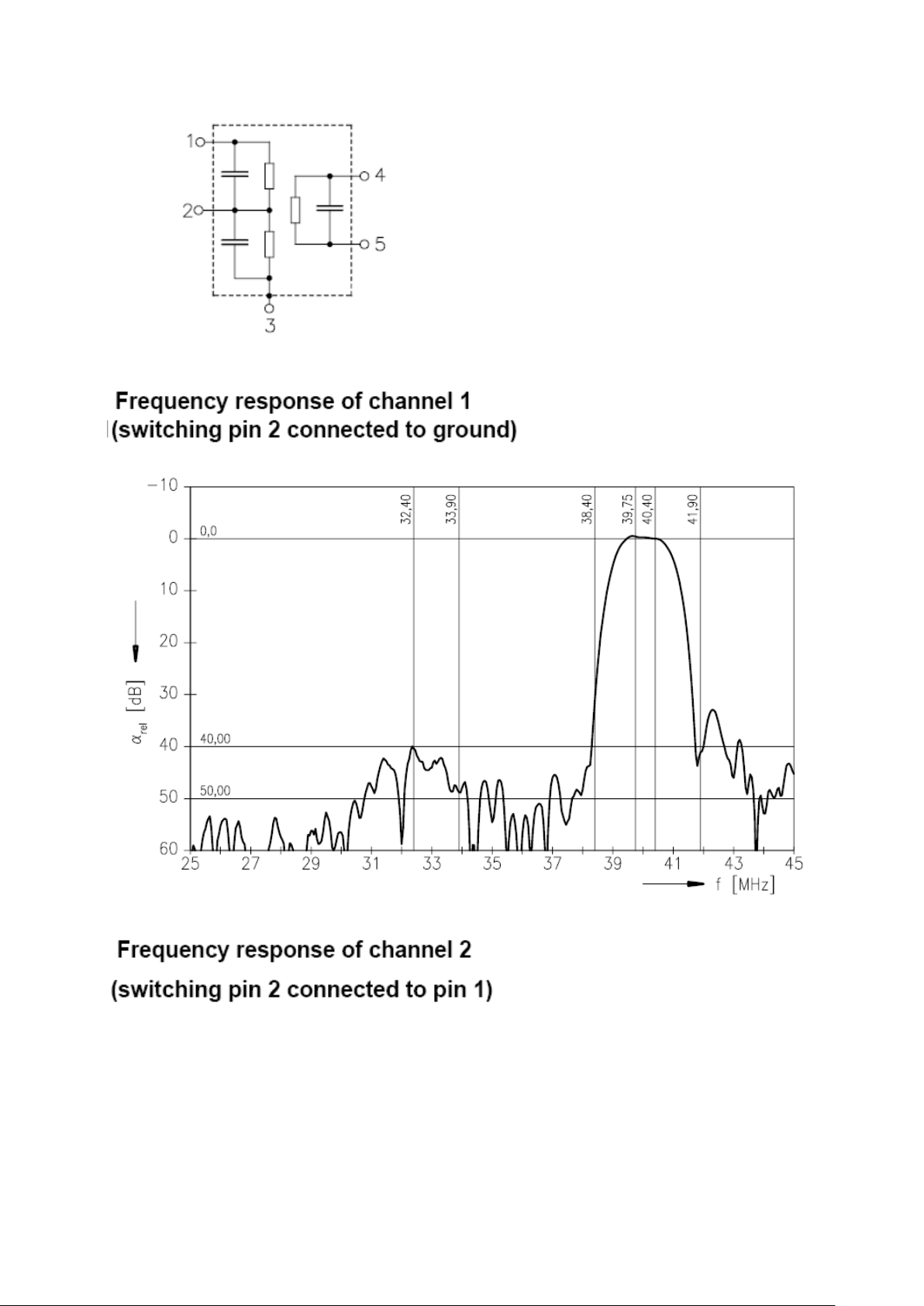
9.1.4. Frequency response:

9.2. IF Filter for Video Applications – Epcos K9658M
9.2.1. Standart:
B/G
D/K
I
L/L’
9.2.2. Features:
TV IF filter with Nyquist slopes at 33.90 MHz and 38.90 MHz
Constant group delay
Pin configuration:
1 Input
2 Input - ground
3 Chip - carrier ground
4 Output
5 Output
9.2.3. Frequency response:

10. 8M x 16 DDR Synchronous DRAM (SDRAM)
10.1. General Description
The EM6A9160 SDRAM is a high-speed CMOS double data rate synchronous DRAM
containing 128 Mbits. It is internally configured as a quad 2M x 16 DRAM with a
synchronous interface (all signals are registered on the positive edge of the clock signal,
CK). Data outputs occur at both rising edges of CK and /CK. Read and write accesses
to the SDRAM are burst oriented; accesses start at a selected location and continue for
a programmed number of locations in a programmed sequence. Accesses begin with
the registration of a BankActivate command which is then followed by a Read or Write
command. The EM6A9160 provides programmable Read or Write burst lengths of 2, 4,
or 8. An auto precharge function may be enabled to provide a self-timed row precharge
that is initiated at the end of the burst sequence. The refresh functions, either Auto or
Self Refresh are easy to use. In addition, EM6A9160 features programmable DLL
option. By having a programmable mode register and extended mode register, the
system can choose the most suitable modes to maximize its performance. These
devices are well suited for applications requiring high memory bandwidth, result in a
device particularly well suited to high performance main memory and graphics
applications.
10.2. Features
Fast clock rate: 300/275/250/200MHz
Differential Clock CK & /CK
Bi-directional DQS
DLL enable/disable by EMRS
Fully synchronous operation
Internal pipeline architecture
Four internal banks, 1M x 16-bit for each bank
Programmable Mode and Extended Mode registers
- /CAS Latency: 3, 4
- Burst length: 2, 4, 8
- Burst Type: Sequential & Interleaved
Individual byte write mask control
DM Write Latency = 0
Auto Refresh and Self Refresh
4096 refresh cycles / 32ms
Precharge & active power down
Power supplies: VDD & VDDQ = 2.5V 5%
Interface: SSTL_2 I/O Interface
Package: 66 Pin TSOP II, 0.65mm pin pitch
Lead-free Package is available.
 Loading...