


VESTEL Service Manual
17MB27-2 02.01.2008
TABLE OF CONTENTS
1 INTRODUCTION....................................................................................................3
2 GENERAL DESCRIPTION...................................................................................3
3 POWER CONSUMPTION.....................................................................................6
4 MICROCONTROLLER PORT CONFIGURATION.........................................6
5 SIDE BOARDS AND CONNECTORS .................................................................7
5.1 Keypad .........................................................................................................................................7
5.2 Infrared & LED ...........................................................................................................................7
5.3 DVB-T .........................................................................................................................................8
5.4 DVD.............................................................................................................................................9
5.5 LVDS .........................................................................................................................................11
5.6 Inverter.......................................................................................................................................12
6 IC SPECIFICATIONS..........................................................................................13
6.1 Microcontoller/Video&Audio Processor (VCT4953G) ............................................................13
6.2 Scaler/De-interlacer (MST5x7A-M)..........................................................................................16
6.3 Audio Amplifier (TDA2822).....................................................................................................19
6.4 HeadPhone Amplifier (TDA1308T) ..........................................................................................19
6.5 Audio Matrix Switch (TEA6422D) ...........................................................................................20
6.6 HDMI Receiver (ANX9021) ....................................................................................................21
6.7 Video Switch (PI5V512)...........................................................................................................23
6.8 Tuner (DTT71306).....................................................................................................................24
6.9 SAW Filter (X6966M)...............................................................................................................25
6.10 I2C Switch (74HCT4053)..........................................................................................................26
6.11 Audio DAC (CS4334)................................................................................................................27
2
VESTEL Service Manual
17MB27-2 02.01.2008
6.12 SPDIF Switch (NLAST4599) ....................................................................................................28
1 INTRODUCTION
The purpose of this document is to define the operation of 17MB27 chassis, capable of driving 15” and
19” TFT LCD panels. It is aimed to provide information to engineering staff to understand the operation
and specs of the TV. The other related technical documents are given in Table1:
Title
1 17MB27 schematics
2 IR receiver and LED display board schematics
3 Keypad board schematics
4 DVD module card schematics
5 DVB-T module card schematics
Table1.1: Related documents
2 GENERAL DESCRIPTION
The system is a low to mid end; 15” and 19” TFT TV solution basically for EU market with VCT4913G
microcontroller / video audio processor chip on a 2-layer PCB. Since the target market is EU, the first
release of the TV will support PAL/SECAM B/G/D/K/I/L/L’.
The target panels are 15” 1024x768 and 19”w 1440x900 TFT-LCD panels. A DVD loader is used to read
DVD content and a DVB-T module card is used to support DVB-T. 15” TV will use 12V/4.16A DC
adapter; 19” TV will use 12V/5.83A DC adapter.
Inputs
• 1xTuner (both analog and DVB-T)
• 1xDVD
• 1xScart
• 1xPC (VGA) (optional) (supports also YPbPr)
• 2xHDMI (optional)
• 1xBack AV (optional)
Outputs
• Speaker (stereo, 2x16 , 2x2Watt)
• Headphone (stereo) (optional)
• Audio line out (stereo) (optional)
• DVD/DVB-T coaxial SPDIF out(optional)
General default features
• Multi System Reception: PAL-SECAM BG-DK-I/I’-L/L’
• Menu system (multi language)
• 100 program storage locations
• OSD (on-screen display)
3

VESTEL Service Manual
17MB27-2 02.01.2008
• Teletext
• IR Control (RC5 and other customer specific protocols)
• “No Ident” Timer
• Child Lock
• Sleep Timer
• WSS (16:9/4:3 Aspect Ratio Auto Switch)
Sound Features
• Equalizer
• FM Radio
• Linear Stereo
• German-NICAM Stereo
• 5-Band Equalizer Control
• SRS TRU Surround (OPT)
• SRS TRU Bass (OPT)
• BBE, WOW (OPT)
Picture Features
• 4:3 PANEL --- 4:3, 16:9, Auto
• WIDE PANEL---4:3,16:9, Auto(opt), Subtitle(opt), Zoom(opt), Panoramic(opt)
• Picture Modes ( Bright, Standard, Soft)
• Media Window Enhancement (MWE)
• White balance settings (warm/normal/cool) for TV&PC
• Backlight brightness setting (movie/normal/bright)
• Multi System Reception : PAL-SECAM BG-DK-I/I’-L/L’
• NTSC Video Playback
• WSS (16:9 / 4:3 Aspect Ratio Auto Switch)
• Channel Type Sorting (Favorite/Sport/Music/News/Movie)
Tuning Options
• FST
• Frequency Search (Optional)
• APS (Auto Search/Name/Sort)
• Auto Search
• CATV/HYPERBAND
Keyboard
• Volume -/ +Button
• Program -/+ Button
• Menu Button
• TV / AV Button
Teletext/OSD
• Simple Text 10 Pages
• Fastext & Top Text (OPT)
• Teletext Languages (ALL)
• Character Based OSD
4

VESTEL Service Manual
17MB27-2 02.01.2008
• OSD Color & Transparency Selection
Electrical features
• 12V 4.16A DC / 100 - 240V AC adapter for 15” TV
• 12V 5.83A DC / 100 - 240V AC adapter for 19” TV
• <1W standby power consumption
System Building Blocks
17MB27 chassis main blocks are as follows:
• Analog Front End : VCTI (Microcontroller+Video Proccessor+Audio Proccessor+IF Demodulator+
Teletext Decoder+ OSD Generator)
• Back End : MST517a-M, MST507a-M (Scaler, Deinterlacer, OSD Generator)
Analog Front End
17MB27 main board consists of two major blocks. The first block is analog front-end and this block is
handled by VCTI chip that is highly multifunctional. VCTI performs Tuner IF demodulation, CVBS,
RGB, SVHS and audio input selection and processing. The audio processor (MSP) supports equalizer,
tone control, volume control, AVL, surround effect etc. The video processor (VSP) handles video
processing such as color standard detection and demodulation, picture alignment (brightness, contrast,
color etc.). The IC also has a teletext decoder with fastext memory. The processed video output is sent to
MST5x7A-M, scaler/deinterlacer in RGB format together with a composite sync.
The TV tuner is PLL controlled symmetrical IF output type. The IF signal is filtered by a single SAW
filter. Inter-carrier sound demodulation is performed by the system. After the SAW filter block, IF signal
is processed by VCTI IF demodulator. Audio signal is digitally filtered in the IF demodulator block. The
same IF signal is buffered and sent to DVB-T module card, tdm1300.
Since VCTI can handle all the audio processing, there is no need for additional audio processor solution on
the board. MSP has two audio inputs which are assigned to the Scart in L/R and Audio Switch L/R output.
MSP has three audio outputs which are assigned to the headphone amplifier L/R input, audio amplifier
L/R input and Audio switch L/R input. The board employs TDA2822M and TDA1308 to drive speaker
and headphone outputs, respectively. Switching control for other audio inputs and outputs (HDMI, Back
AV, PC, DVD, and DVB-T) is achieved by an I2C controlled audio switch (TEA6422).
Back End
MST5x7A-M has two ADC inputs. First ADC input is assigned to the VCTI RGB output. Other
RGB/YPbPr inputs are multiplexed for the second ADC input. HDMI receiver ANX9021 analog output,
VGA RGB input and the synchronization signals are multiplexed by a primary RGB switch (PI5V512).
MST5x7A-M has an embedded LVDS transmitter. It can be configured as either single LVDS, or dual
LVDS output.
5
VESTEL Service Manual
17MB27-2 02.01.2008
There are three PWM output ports. PWM0 is assigned to analog/digital dimming control for the backlight,
PWM1 is used for backlight on/off and panel logic power supply on/off control and PWM2 is used to
control PC/HDMI switch IC (PI5V512).
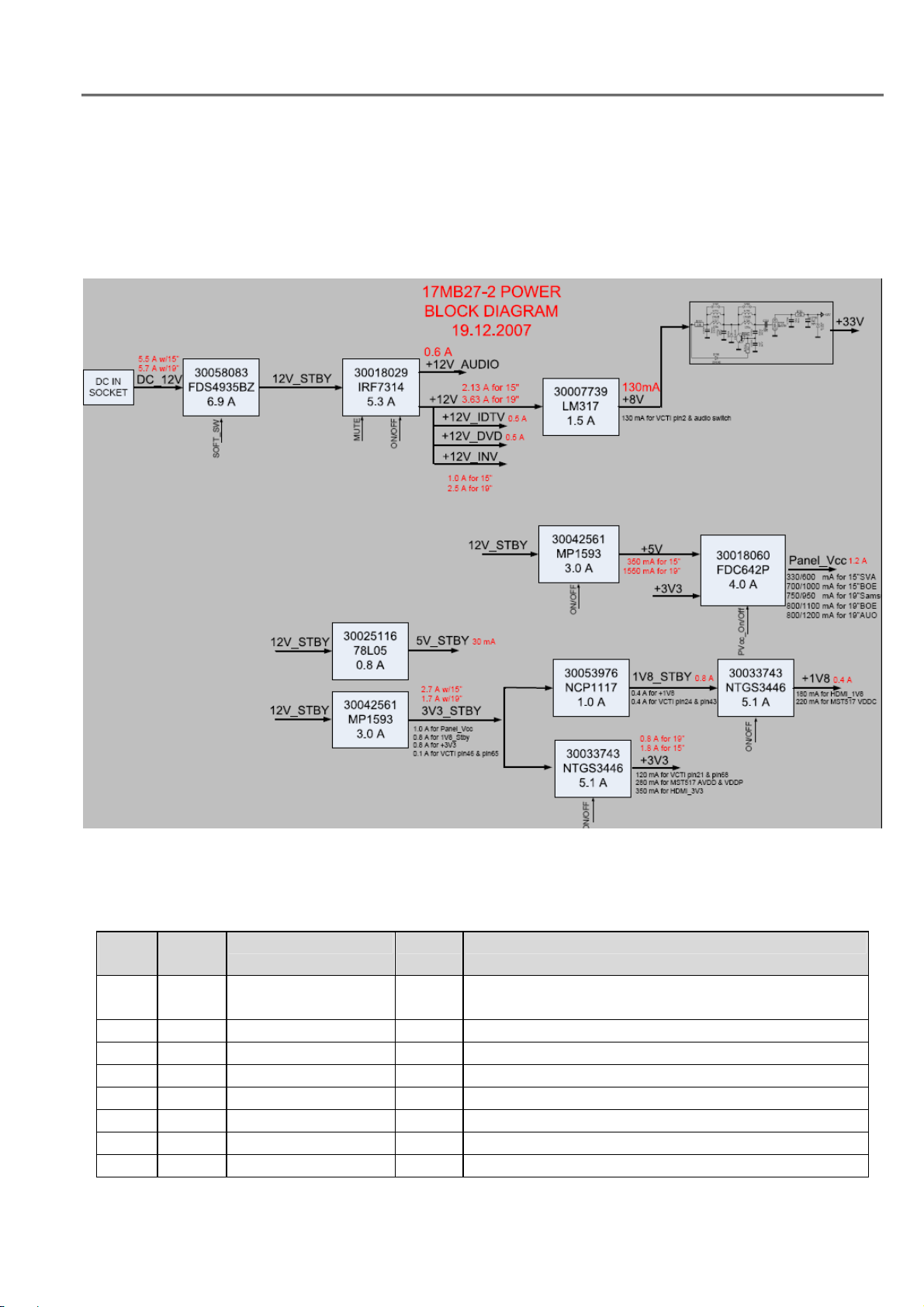
3 POWER CONSUMPTION
The power block diagram with the currents drawn is shown below:
4 MICROCONTROLLER PORT CONFIGURATION
PIN
NO
47 P10 MST_RESET
48 P11 TV_RXD I IDTV UART receive signal
49 P12 TV_TXD O IDTV UART transmit signal
50 P13 IRQ O IDTV interrupt request signal
51 P14 KEY I Keyboard function select
52 P15 SC_PIN8 I Scart function select
53 P16 DVD_IR_ON/OFF O DVD infrared signal on/off control
54 P17 POWCON O Standby on/off control
PORT
NAME
SIGNAL NAME TYPE FUNCTION
PROTECT
O
I
Scaler reset
Short circuit detection
6
VESTEL Service Manual
17MB27-2 02.01.2008
PIN
NO
PORT
NAME
SIGNAL NAME TYPE FUNCTION
55 P20 HDMI_HP_INV O HDMI hot plug signal
56 P21 CS O Switching control for Mstar bus and system I2C
62 Safety VCTI_HS O VCTI composite sync output
78 FBIN DVD_SENSE I DVD module detection
85 Vert+ TV/DVB_SW O IDTV/TV I2C and AGC switch control for tuner
27 P22 WP O Write protection control for NVM
28 P23 IR I Infrared input
Table 4.1 VCTI port configuration
5 SIDE BOARDS & CONNECTORS
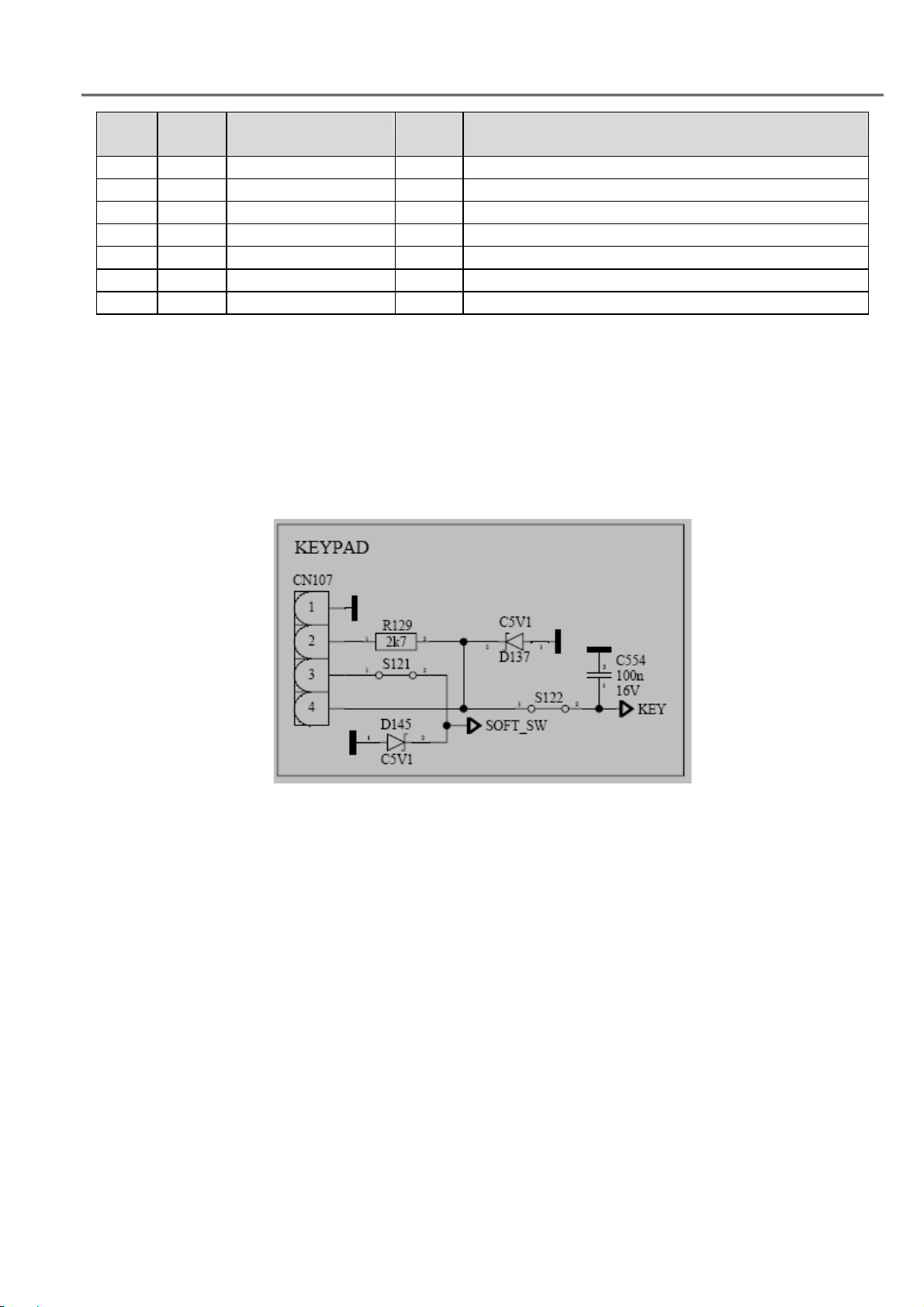
5.1 Keyboard
A four-pin connector is used between 17mb27 and the keyboard:
Figure 5.1.1: Keyboard connector
KEY signal is sent directly to microcontroller ADC port and depending on the voltage level of KEY
signal, microcontroller performs one of these actions: menu, program+, program-, volume+, volume-, and
source.
SOFT_SW signal is used to switch between “power-off” and “standby” modes.
5.2 Infra-red & LED
A five-pin connector is used between 17mb27 and the LED board:
7

VESTEL Service Manual
17MB27-2 02.01.2008
Figure 5.2.1: LED board connector
Pin2 and pin3 carry the control signals for the LED. Pin4 carries the infra-red signal to the microcontroller.
Pin5 is used to power up the LED board.
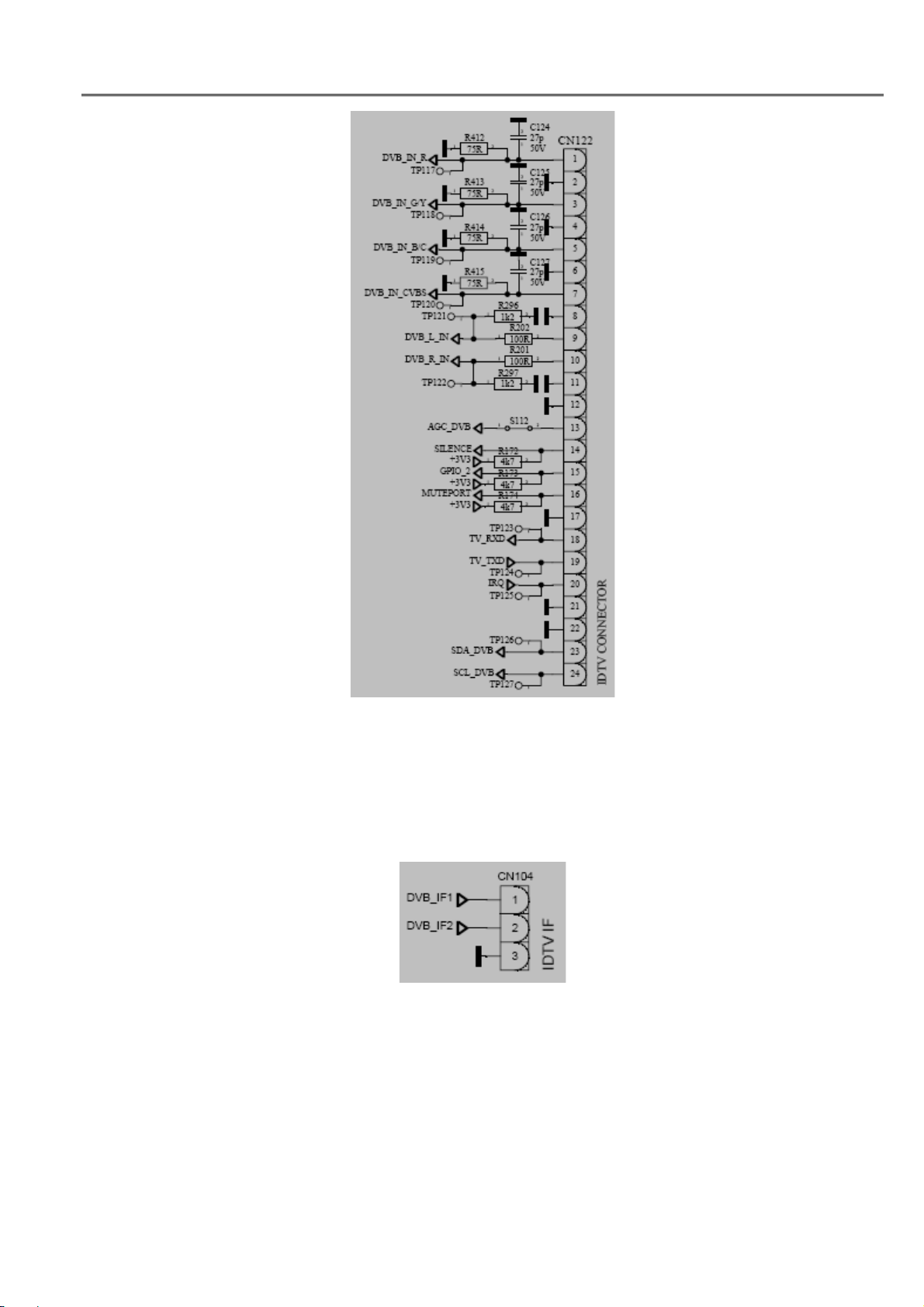
5.3 DVB-T module board
DVB-T module board (tdm1300) is used to receive digital terrestrial broadcast signals. Three cables are
used to connect 17mb27 and tdm1300: power, data, and IF.
12V (500mA) is sent to tdm1300 by power cable:
Figure 5.3.1: DVB-T module card power connection on 17mb27
Analog RGB(YPbPr), CVBS, stereo audio, tuner control (SCL, SDA, AGC), and three GPIO port outputs
of tdm1300, together with UART ports (TV_RXD, TV_TXD, IRQ) are carried by data cable.
8
VESTEL Service Manual
17MB27-2 02.01.2008
Figure 5.3.2: DVB-T data connector on 17mb27
Tdm1300 board has no tuner on it. Instead, the tuner of 17mb27 is used for both analogue and digital
reception. Tuner is controlled by either the 17mb27 microcontroller (VCTI), or tdm1300 board
microcontroller. The IF (intermediate frequency) output of the tuner is sent to tdm1300 board for digital
reception.
Figure 5.3.3: IDTV IF connector on 17mb27
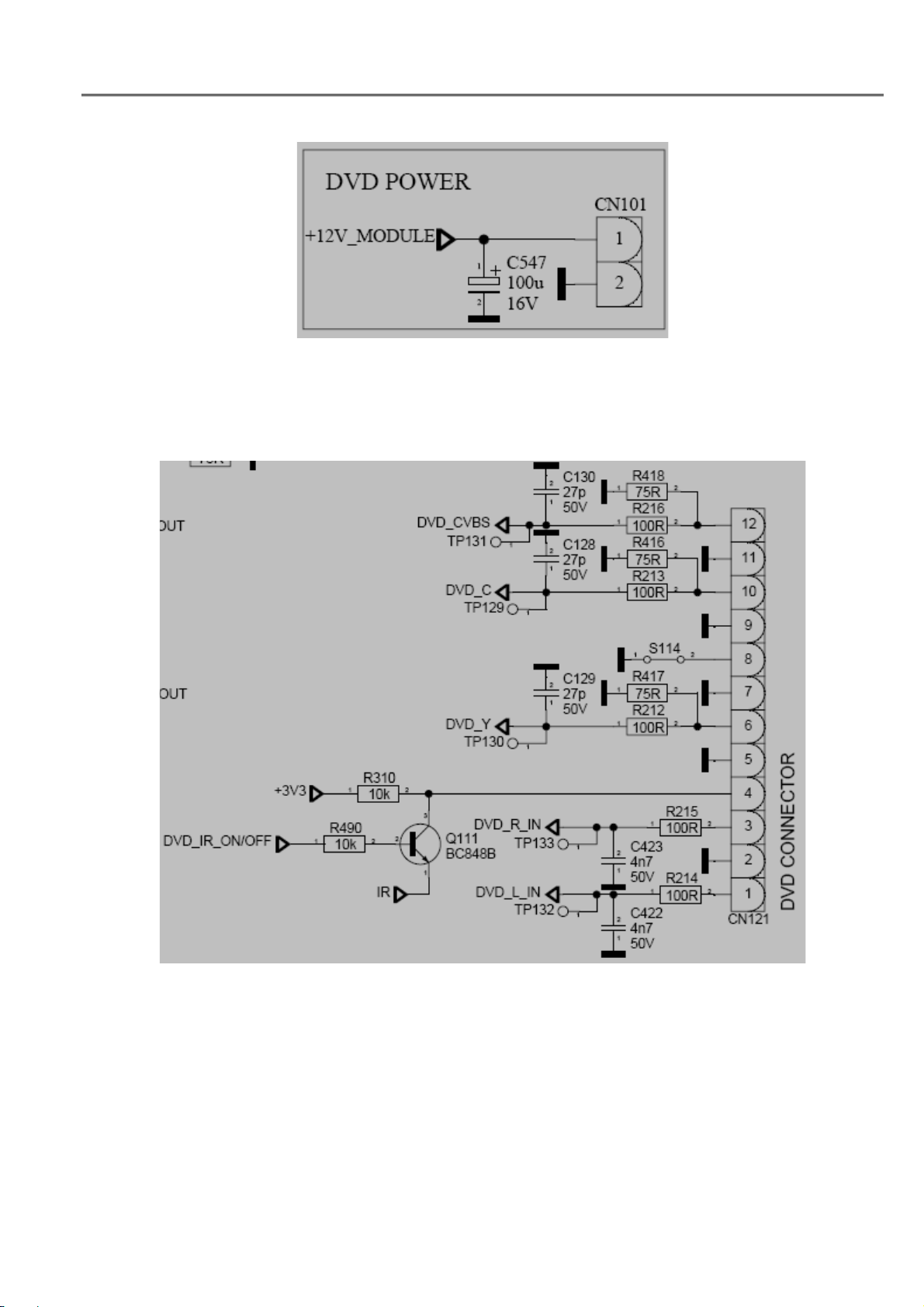
5.4 DVD module board
DVD module board has two parts: a loader and an electronic card. Electronic card controls the loader and
has connections with 17mb27 and DVD keypad.
Three cables are used to connect 17mb27 and DVD electronic card: power, data, and sense.
9
VESTEL Service Manual
17MB27-2 02.01.2008
12V (500mA) is sent to DVD electronic card by power cable:
Figure 5.4.1: DVD module board power connection on 17mb27
Y/C and/or CVBS video, stereo audio outputs and infra-red input of DVD module board is carried on data
cable:
Figure 5.4.2: DVD data connector on 17mb27
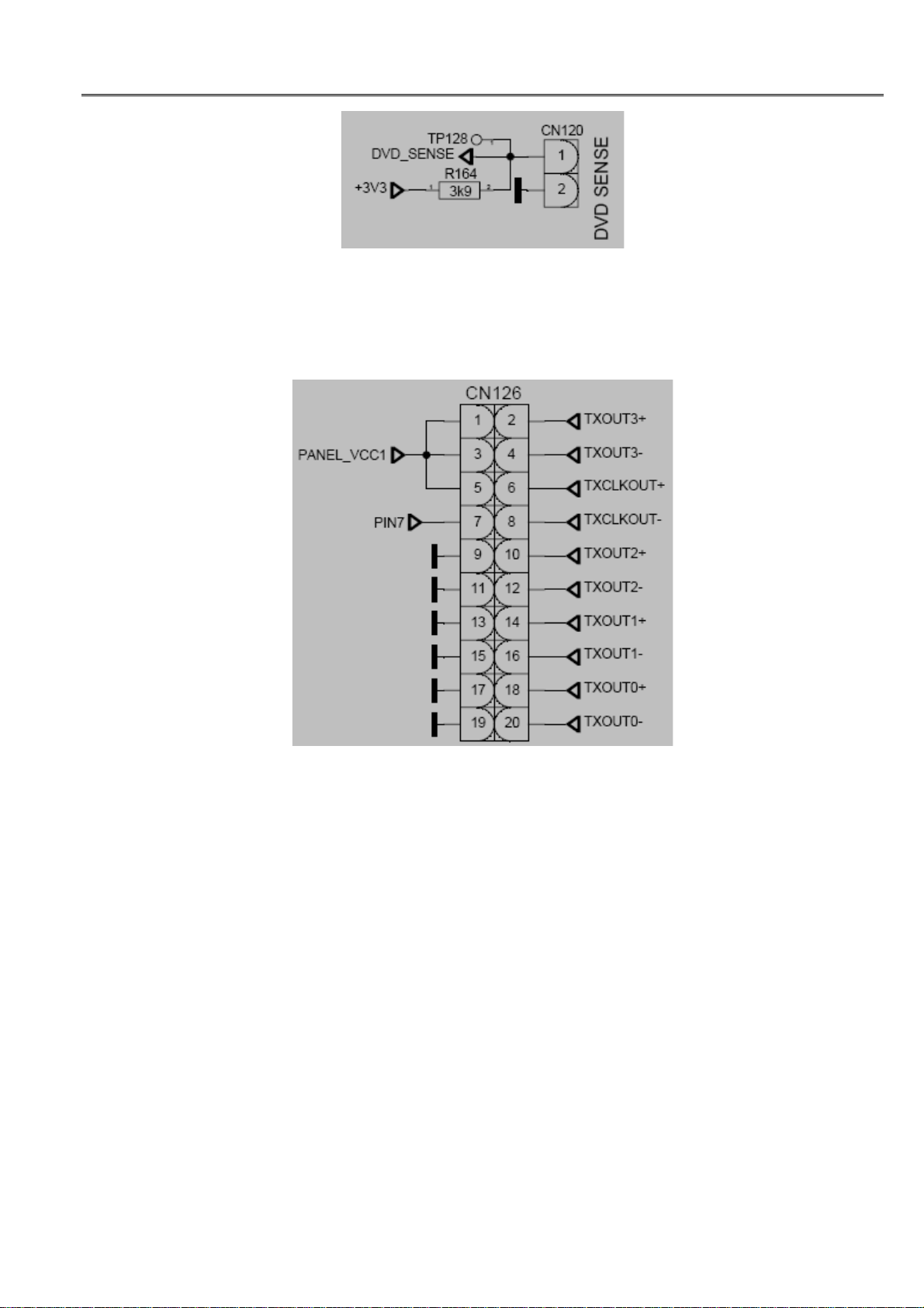
When a DVD is inserted into the loader, the DVD electronic card sends an interrupt signal (DVD_SENSE)
to the 17mb27 microcontroller:
10
VESTEL Service Manual
17MB27-2 02.01.2008
Figure 5.4.3: DVD_SENSE connector on 17mb27
5.5 LVDS connector
MST507A-M is used for single LVDS output and MST517A-M is used for dual LVDS output on 17mb27:
Figure 5.5.1: Single LVDS output connector on 17mb27
11
VESTEL Service Manual
17MB27-2 02.01.2008
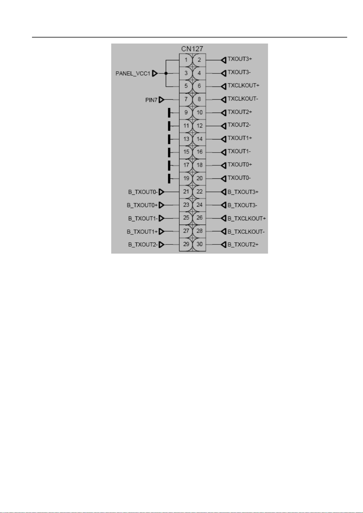
Figure 5.5.2: Dual LVDS output connector on 17mb27
Panel_Vcc1 is the power input for the panel LCD module. PIN7 signal is a logic 1 or 0 signal depending
on the panel type.
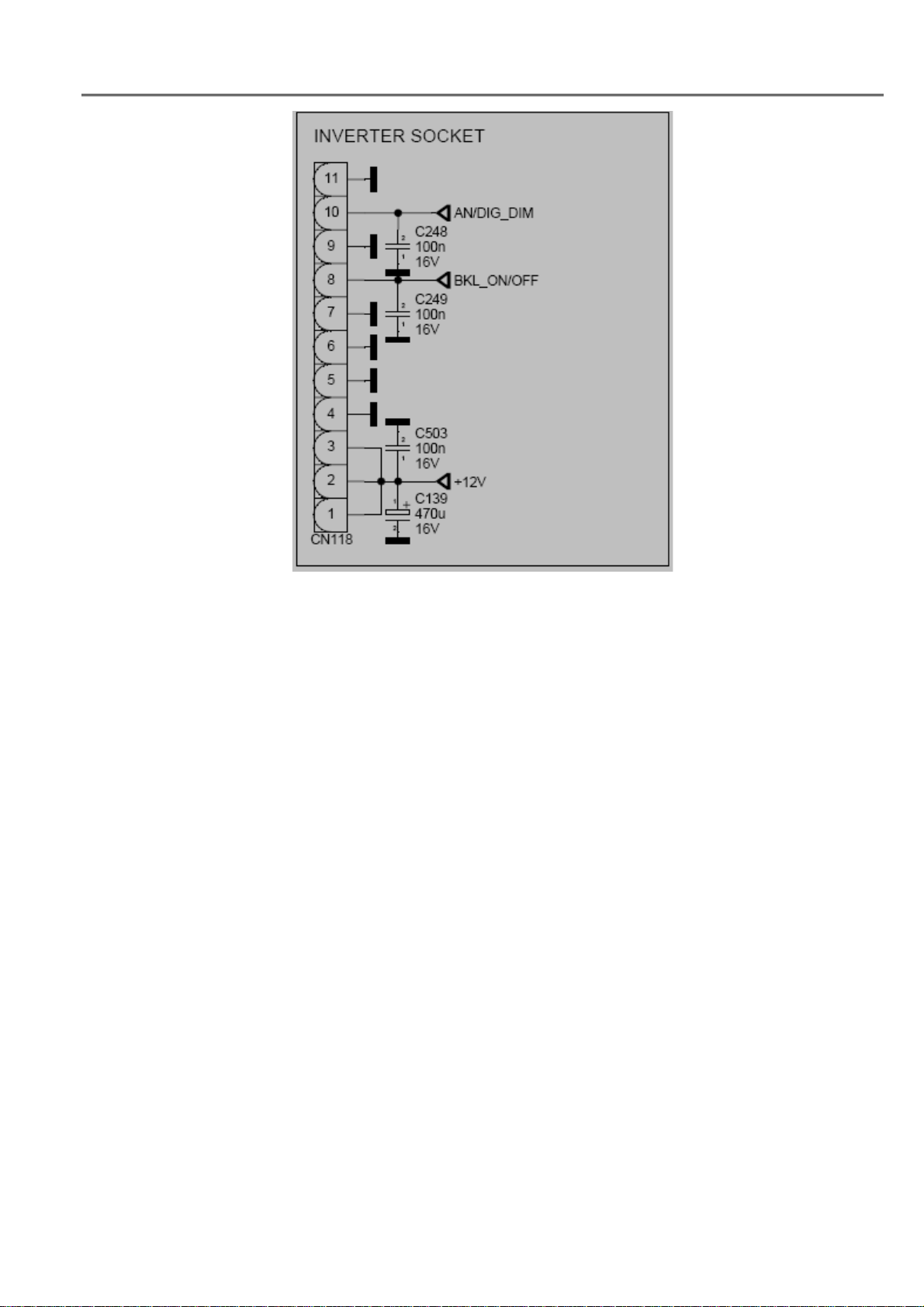
5.6 Inverter
12V power, backlight on/off control, and dimming control signal are sent to the inverter board:
12
VESTEL Service Manual
17MB27-2 02.01.2008
Figure 5.6.1: Inverter connector on 17mb27
6 IC SPECIFICATIONS
6.1 Microcontoller/Video&Audio Processor (VCT4913G)
VCTI49xy is composed of microcontroller, video proccessor, display and deflection processor, sound
proccessor and IF blocks as shown in below figure .
13

VESTEL Service Manual
17MB27-2 02.01.2008
Figure 6.1.1: VCTI49xy block diagram
14

VESTEL Service Manual
17MB27-2 02.01.2008
Figure 6.1.2: Detailed block diagram of VCTI49xy
VCTI49xyl family has two package types; PSSDIP88 and PMQFP144. PSSDIP88 package is chosen
because of its convenience in the soldering process. PSSDIP88 package has two versions; 1 and 2.
PSSDIP88-2 package is the “pinning mirrorred” version of PSSDIP88-1 and is preferred to be used for
layout compatibility.
15

VESTEL Service Manual
17MB27-2 02.01.2008
Figure 6.1.3: VCTI pinning diagram
6.2 Scaler/De-interlacer (MST5x7A-M)
The MST507A-M and MST517A-M are total solution graphics processing ICs for LCD displays with
panel resolutions up to XGA and WXGA+ / SXGA+ respectively. They are configured with a high-speed
integrated triple-ADC/PLL, a high quality display processing engine, and an integrated multi-purpose
output display interface that can support all major panel interface formats. To further reduce system costs,
the MST517A-M also integrates intelligent power management control capability for green-mode
requirements and spread spectrum support for EMI management.
Input mode detection support analyzes input video signal (H/V polarity, H/V frequency, interlace/field
detect) – extensive status registers support robust detection of all VESA and IBM modes.
16

VESTEL Service Manual
17MB27-2 02.01.2008
MST has a built-in OSD generator with 291 character font programmable RAM. OSD generator supports
2/4/8 multi-color fonts, 8/16/256 color palette and 1K code attributes.
MST also supports dual channel 6-bit/single channel 8-bit TTL panel interface and 6/8-bit LVDS panel
interface. MST517A-M supports up to WXGA+ (1440x900)/SXGA+ (1400x1050) display resolution with
up to 135 MHz dot clock and MST507A-M supports up to XGA (1024x768) display resolution with up to
85 MHz dot clock.
Figure 6.2.1: Internal block diagram of MST5x7A-M
17

VESTEL Service Manual
17MB27-2 02.01.2008
Figure 6.2.2: Pinning of MST5x7A-M
18

VESTEL Service Manual
17MB27-2 02.01.2008
PIN
NO
PORT
NAME
SIGNAL NAME TYPE FUNCTION
28 PWM0 AN/DIG_DIM O Analog or digital dimming control
23 PWM1 BKL_ON/OFF
PVCC_ON/OFFO O
Backlight On/Off Control
Panel Logic Power On/Off control
33 PWM2 PC/HDMI_SW O Video switching control
Table 6.2.1: MST5x7A-M port allocation
6.3 Audio Amplifier (TDA2822M)
TDA2822M is a dual low-voltage power amplifier in 8-lead minidip package. It is used in bridge
configuration in 17mb27. The features of this amplifier are:
• Supply voltage down to 1.8 V
• Low crossover distortion
• Low quiescent current
• Bridge or stereo configuration
Figure 6.3.1: TDA2822M package
6.4 Headphone Amplifier (TDA1308T)
TDA1308T is an integrated class AB stereo headphone driver contained in an SO8, DIP8, or a TSSOP8
plastic package. SO8 package is used in 17mb27. The device is fabricated in a 1mm CMOS process. The
main features of this IC are:
• Wide temperature range
• No switch ON/OFF clicks
• Power supply ripple rejection
• Low power consumption
• Short-circuit resistance
• High performance
– high signal-to-noise ratio
– high slew rate
– low distortion
19

VESTEL Service Manual
17MB27-2 02.01.2008
• Large output voltage swing
Figure 6.4.1: TDA1308T block diagram
Figure 6.4.2: Pinning of TDA1308T
6.5 Audio Matrix Switch (TEA6422D)
TEA6422D is a bus-controlled audio matrix switch in an SO28 plastic monopackage. The main features of
TEA6422 D are:
• 6 stereo inputs
• 3 stereo outputs
• Gain control
• Cascadable (2 different addresses)
• Serial bus controlled
• Low noise
• Low distortion
• ESD protection
• Wide dynamic range (3 Vrms)
20

VESTEL Service Manual
17MB27-2 02.01.2008
Figure 6.5.1: TEA6422D pinning
6.6 HDMI Receiver (ANX9021)
The ANX9021 is an advanced multimedia receiver compliant with High Definition Multimedia Interface
(HDMI) Specification 1.2. HDMI is the first transport standard to unify digital video, audio, and control da
ta over lowcost cables. It connects digital television, flat panel displays and project systems digitally to
multimedia sources: DVD players, high definition settop boxes, digital video tape recorders, and personal
computers.Digital transmission, in turn, delivers an uncompromising multimedia experience. HDMI also i
ncludes encryption for premium contents pursuant to the HighBandwidth Digital Content Protection (HDC
P) standard. The ANX9021 embeds the HDCP keys and key selection vectors to reduce manufacturing co
mplexity and system cost.
The ANX9021 receives two HDMI data streams and decodes the selected input into digital audio and vide
o data outputs. The receiver incorporates Analogix’s proprietary WideEye™ architecture, which has receiv
ed considerable industry acclaim when introduced in Analogix’s 6.25 Gbps SerDes products for telecom a
nd datacom applications. Applying the same advanced techniques in ANX9021 allows displays systems to
achieve errorfree HDMI reception over long, inexpensive cables up to 20 meters and assure the widest ran
ge of interoperability against uncertain qualities of cheap cables from lowcost suppliers as the standard ma
tures.
The ANX9021 can receive and output up to eight digital audio channels at up to 192 kHz sampling rate, m
aking it the leading component for integrated home theaters and high definition televisions. The device sup
ports direct connections to a wide selection of audio DACs and decoders through industry standard I2S or
S/PDIF interfaces. The ANX9021 is offered in 144-lead TQFP lead-free packages.
The main features of ANX9021 are:
21

VESTEL Service Manual
17MB27-2 02.01.2008
• Dual-channel HDMI receiver supporting link data rate up to 1.65 Gbps
• HDMI 1.2, HDCP 1.1 and DVI 1.0 compliant
• WideEye™ architecture for signal conditioning and equalization
o support cable length up to 20m
o better than 10E-12 bit error rate
• Digital interface to video processor supporting
o 24-bit RGB / YCbCr 4:4:4
o 16/20/24 bit YCbCr 4:2:2
o 8/10/12 bit YCbCr 4:2:2 (ITU BT-656)
o 12-bit double data rate interface
• Color space conversion: RGB to/from YCbCr both directions (601 and 709 standards)
• Auto video mode configuration
• Analog RGB/YPbPr output with 8-bit linearity
• Digital audio interface
o 32 to 192 kHz audio sampling rate
o Up to 4 I2S interface for 8-channel audio
o S/PDIF interface supporting PCM, Dolby Digital™, DTS™ digital audio transmission
using IEC 60958 and IEC 61937
o Configurable soft mute
• Integrated HDCP decryption engine and pre-programmed keys
• Programmable power management with automatic shutdown for power conservation
• Supports automated link integrity checking
• 144-lead TQFP package supporting lead-free and green requirements
Figure 6.6.1: Internal Block Diagram of ANX9021
22

VESTEL Service Manual
17MB27-2 02.01.2008
6.7 Video Switch (PI5V512)
PI5V512 is a wide-bandwidth 5-port 2:1 mux/demux video switch with High-Z outputs. The main features
of PI5V512 are:
• High-performance, low-cost solution to switch between video sources
• Wide bandwidth: 550 MHz
• Low On-Resistance: 5
• Low crosstalk at 10 MHz: –90dB
• Ultra-low quiescent power (0.1A typical)
• Single supply operation: +5.0V
• Fast switching: 10ns
• Packaging (Pb-free & Green available): 24-pin 150-mil wide plastic QSOP (Q)
Figure 6.7.1: Block diagram of PI5V512
23

VESTEL Service Manual
17MB27-2 02.01.2008
Figure 6.7.2: Pin configuration of PI5V512
Figure 6.7.3: Truth table of PI5V512
6.8 Tuner (DTT71306)
DTT713xx is a digital terrestrial tuner designed for reception in VHF I, VHF III and UHF, compliant with
the European digital terrestrial standard ETS 300744 and CENELEC standards EN 55013 and EN 55020.
It covers all channels from 44.25 MHz to 863.25 MHz
The main features of DTT713xx are:
• Integrated tuner for digital and anlog broadcasting
• Low phase noise, high sensitivity performance
• Small size: 50mm x 35mm x 12mm
• Internal wide band AGC
• 3V3 and 5V I2C bus programmable
• General-purpose port output
• Antenna power supply input
24

VESTEL Service Manual
17MB27-2 02.01.2008
Figure 6.8.1: Block diagram of DTT713xx
6.9 SAW Filter (X6966M)
X6966M is a SAW (Surface Acoustic Wave) band-pass filter at 36.125 MHz.
Figure 6.9.1: Package of X6966M
25

VESTEL Service Manual
17MB27-2 02.01.2008
Figure 6.9.2: Pin configuration of X696M
6.10 I2C Switch (74HCT4053)
74HCT4053 is a triple 2-channel analog mux/demux with a common enable input. Each
multiplexer/demultiplexer has two independent inputs/outputs (nY0 and nY1), a common input/output
(nZ) and three digital select inputs (S1 to S3).
Figure 6.10.1: Pin configuration of 74HCT4053
Figure 6.10.2: Logic symbol of 74HCT4053
26

VESTEL Service Manual
17MB27-2 02.01.2008
Figure 6.10.3: Function table of 74HCT4053
6.11 Audio DAC (CS4334)
CS4334 is a 8-pin, 24-bit, 96 kHz stereo D/A converter. The CS4334 family is based on Delta-Sigma
modulation, where the modulator output controls the reference voltage input to an ultra-linear analog lowpass filter. This architecture allows for infinite adjustment of sample rate between 2 kHz and 100 kHz
simply by changing the master clock frequency.
The main features of CS4334 are:
• Complete stereo DAC system: interpolation, D/A, output analog filtering
• 24-bit conversion
• 96 dB dynamic range
• -88 dB THD+N
• Low clock jitter sensitivity
• Single +5V power supply
• Filtered line level outputs
• On-chip digital de-emphasis
• Popguard
27

VESTEL Service Manual
17MB27-2 02.01.2008
Figure 6.11.1: Block diagram of CS4334
6.12 SPDIF Switch (NLAST4599)
The NLAST4599 is an advanced high speed CMOS single pole double throw analog switch fabricated
with silicon gate CMOS technology. It achieves high speed propagation delays and low ON resistances
while maintaining low power dissipation. This switch controls analog and digital voltages that may vary
across the full powersupply range (from VCC to GND).
The device has been designed so the ON resistance (RON) is much lower and more linear over input
voltage than RON of typical CMOS analog switches.
The channel select input structure provides protection when voltages between 0 V and 5.5 V are applied,
regardless of the supply voltage. This input structure helps prevent device destruction caused by supply
voltage input/output voltage mismatch, battery backup, hot insertion, etc.
Main features of NLAST4599 are:
• Select Pin Compatible with TTL Levels
• Channel Select Input OverVoltage Tolerant to 5.5 V
• Fast Switching and Propagation Speeds
• BreakBeforeMake Circuitry
• Low Power Dissipation: ICC = 2 _A (Max) at TA = 25°C
• Diode Protection Provided on Channel Select Input
• Improved Linearity and Lower ON Resistance over Input Voltage
• Latchup Performance Exceeds 300 mA
• ESD Performance: HBM > 2000 V; MM > 200 V
28

VESTEL Service Manual
17MB27-2 02.01.2008
• Chip Complexity: 38 FETs
Figure 6.12.1: Pin assignment of NLAST4599
Figure 6.12.2: Logic symbol of NLAST4599
Figure 6.12.3: Function table of NLAST4599
29

A0

1 2 3 4 5 6 7 8
C124
2
R412
12
DVB_IN_R
TP117
BACK AV
A
JK102
JK105
JK109
F131
2
12
3
600R
1
F132
2
12
3
600R
1
F133
2
12
3
600R
1
FAVINL
C418
2
4n7
1
50V
FAVINR
C419
2
4n7
1
50V
12
75R
D101
R103
12
C12V
12
R211
100R
2
1
C466
100p
50V
CVBS_IN
B
AUDIO LINE-OUT
F130
2
12
3
JK101
JK104
C
LINE_OUT_L
PC AUDIO IN
JK103
JK106
600R
1
F129
2
12
3
600R
1
S3
12
F135
2
12
3
600R
1
F136
2
12
3
600R
1
SPDIF_OUT
R135
12
680R
C416
2
4n7
1
50V
R136
12
680R
C417
2
4n7
1
50V
LINE_OUT_R
PCIL
C420
2
4n7
1
50V
PCIR
C421
2
4n7
1
50V
C349
2
150p
1
50V
C350
2
150p
1
50V
LINE_OUT_L
LINE_OUT_R
D
PC CONNECTOR
15
14
13
12
11
PC_SCL
PC_SDA
12
12
2k2
2k2
R113
R114
12
12
S2
S1
VGA_VS
VGA_HS
HD RGB INPUT FOR MST517
C161
R274
12
470R
12
1n
50V
C117
R143
GAIN2
RAIN2
BAIN2
12
47R
C433
2
10p
1
50V
R142
12
47R
R141
12
47R
C434
2
10p
1
50V
R140
12
47R
R139
12
47R
C435
2
10p
1
50V
R138
12
47R
12
47n
16V
C118
12
47n
16V
C119
12
47n
16V
C120
12
47n
16V
C116
12
47n
16V
C115
12
47n
16V
PC/HDMI SWITCH
R383
PC/HDMI_SW
12
1k
HDMI_PB
VGA_B
BAIN2
HDMI_Y
VGA_G
GAIN2
HDMI_PR
VGA_R
SOY
GAIN
GAIN-
RAIN
RAIN-
BAIN
BAIN-
1
S
2
IA0
3
GND1
4
IA1
5
YA
6
IB0
U709
7
GND2
PI5V512
8
IB1
9
YB
10
IC0
11
IC1
12 13
GND3 YC
SCART CVBS OUT
+8V
IF_CVBS_OUT
SWITCH BYPASS
HDMI_PB
VGA_B
HDMI_Y
VGA_G
HDMI_PR
VGA_R
HDMI_HS
VGA_HS
HDMI_VS
VGA_VS
24
VCC
23
EN
22
IE0
21
GND6
20
IE1
19
YE
18
ID0
17
GND5
16
ID1
15
YD
14
GND4
C174
2
100n
1
16V
R380
R303
12
12
12
12
12
12
12
12
12
12
12
C175
2
100n
1
16V
HDMI_VS
VGA_VS
SW_VS
HDMI_HS
VGA_HS
SW_HS
RAIN2
R273
470R
12
27k
3
12
2
Q112
BC848B
1
R130
12
10k
12
S102
S101
S103
S104
S108
S107
S105
S106
S109
S110
910R
R286
820R
12
F134
600R
C176
2
100n
1
16V
C1
12
100n
16V
C2
12
100n
16V
2
BAIN2
GAIN2
RAIN2
SW_HS
SW_VS
+5V
1
BC858B
Q158
3
R411
12
75R
C458
2
47p
1
50V
SC_V_OUT
SC101
10
E
9
VGA_5V
8
7
6
5
C106
4
3
2
12p
1
50V
2
1
CN111
D125
F
D126
3
3
BAV99
12
BAV99
12
C108
C107
2
2
12p
12p
1
1
50V
50V
75R
75R
R104
12
75R
R105
R106
12
12
+5V
R203
12
100R
R204
12
100R
R205
12
100R
VGA_B
VGA_G
VGA_R
D127
3
BAV99
12
PC DDC EEPROM
C173
12
100n
16V
1
A0
2
A1
ST24LC21
3
A2
45
GND SDA
EE_WP
8
VCC
U691
7
WP
6
SCL
S164
12
R149
TP101
1
D123
3k3
3k3
3k3
R151
R150
12
12
12
S163
12
1
1
TP1031TP104
S113
12
BAV99
D124
3
12
VGA_VS
BAV99
3
12
3
12
12
12
D129
R260
220R
R261
220R
+5V
BAV70
VGA_5V
PC_SCL
PC_SDA
YPbPr via VGA
12
+5V
TP102
SOFTWARE UPDATE
R304
BC848B
VCTI_PROG_EN
21
20
19
18
17
16
15
14
13
12
11
SCART RB1
10
9
8
7
6
5
4
3
2
1
F164
600R
12
C557
2
100n
1
16V
VCTI_PROG_EN
HWSDA
10k
3
12
2
Q113
1
R309
12
+5V
10k
C12V
75R
R108
12
C348
2
150p
1
50V
S111
12
VCTI_PROG_EN
R492
12
75R
D134
12
C5V1
R491
12
75R
C172
2
100n
1
16V
F125
12
600R
F126
12
600R
F127
12
600R
F128
12
600R
R499
10k
10k
R500
12
R159
12
10k
R305
1
Q116
2
BC848B
3
RX-DATA
S162
12
R505
12
10k
12
D102
C347
2
150p
1
50V
12
SC_V_OUT
C12V
12
D103
C5V1
TX-CLOCK
C5V1
D135
RX-DATA
12
D104
C12V
SC_IN_L
C413
2
4n7
1
50V
R133
12
680R
C414
2
4n7
1
50V
SC_IN_R
C412
2
4n7
1
50V
R134
12
680R
C415
2
4n7
1
50V
VGA_G
VCTI_PROG_EN
10k
12
R306
BC848B
+5V
EE_WP
3
2
Q187
BC848B
1
R206
100R
R210
12
100R
R109
12
75R
12
D132
C123
2
27p
1
50V
12
2
1
SC_PIN8
C122
27p
50V
C5V1
D130
C121
2
27p
1
50V
SC_L_OUT
C345
2
150p
1
50V
SC_R_OUT
C346
2
150p
1
50V
HWSCL
10k
3
12
2
Q114
1
R308
12
10k
SC_V_IN
D131
12
C5V1
SC_FB
R207
12
100R SC_R
R110
12
75R
C5V1
12
D133
R208
12
100R SC_G
R111
12
75R
12
R209
12
100R SC_B
R107
12
75R
DVD_IR_ON/OFF
Q115
C12V
12
D140
R307
1
12
2
BC848B
3
TX-CLOCK
+3V3
R490
12
SCH NAME :
DRAWN BY :
10k
R310
12
10k
2
10k
IR
DVD_L_IN
DVD_R_IN
INPUT & OUTPUT
HUSEYIN ERTURK CETIN
DVB_IN_G/Y
DVB_IN_B/C
DVB_IN_CVBS
DVD_CVBS
TP131
DVD_C
TP129
DVD_Y
TP130
3
DVD_R_IN
Q111
BC848B
1
DVD_L_IN
TP118
TP119
TP120
DVB_L_IN
DVB_R_IN
1
R506
12
R507
12
PROJECT NAME :
1
12
1
12
1
12
1
TP121
TP122
AGC_DVB
SILENCE
+3V3
GPIO_2
+3V3
MUTEPORT
+3V3
SDA_DVB
SCL_DVB
DVD_SENSE
+3V3
C130
2
27p
1
50V
C128
2
27p
1
50V
1
C129
2
27p
1
50V
1
TP133
TP132
10k
10k
75R
R413
75R
R414
75R
R415
75R
1
1
TV_RXD
TV_TXD
1
1
27p
1
50V
C125
2
27p
1
50V
C126
2
27p
1
50V
C127
2
27p
1
50V
R296
12
1k2
R202
12
100R
R201
12
100R
R297
12
1k2
S112
12
R172
12
4k7
R173
12
4k7
R174
12
4k7
TP123
1
TP124
1
IRQ
TP125
1
TP126
1
TP127
1
DVB_IF1
DVB_IF2
R164
12
3k9
R418
12
75R
R216
12
100R
R416
12
75R
R213
12
100R
S114
12
R417
12
75R
R212
12
100R
R215
12
100R
C423
2
4n7
1
50V
R214
12
100R
C422
2
4n7
1
50V
17MB27-2
87654321
CN122
1
2
3
4
5
6
7
8
9
10
11
12
13
14
15
16
17
18
19
20
21
22
23
24
CN104
1
2
3
CN120
1
2
12
11
10
9
8
7
6
5
4
3
2
1
CN121
SHEET:
9-26-2007_8:27
A
B
C
IDTV CONNECTORIDTV IFDVD SENSEDVD CONNECTOR
D
E
F
A3
OF:
16
AXM

1 2 3 4 5 6 7 8
FLASH PROG. & VCTI DEBUG
CN113
A
MSTAR DEBUG
CN123
B
KEYPAD
CN107
C
IR INTERFACE
CN114
D
TUNER I2C & AGC
E
AGC_DVB
EEPROM
F
S126
12
1
12
2
S123
+3V3
KEY
3
S124
12
4
5
+5V
1
2
3
4
1
2
3
4
12
+3V3
HWSDA
S125
HWSCL
R317
12
10k
R229
12
100R
R230
12
100R
R318
12
+5V
10k
+5V
R129
12
2k7
S121
12
D145
12
C5V1
1
2
3
4
5
SCL_DVB
SCL_5V
AGC_SW
AGC_TV
S158
12
S159
12
S161
12
S160
12
S119
12
C553
2
100n
1
16V
S120
12
U692
74HCT4053
1
2Y1
2
2Y0
3
3Y1
4
3Z
5
3Y0
6
E
7
VEE
89
GND S3
U698
24LC32
1
E0
2
3
45
VCC
E1
VC
E2
SCL
VSS SDA
R445
12
33k
2
1
3
Q125
BC848B
Q122
3
BC848B
2
R444
12
33k
C5V1
12
D137
S122
12
SOFT_SW
LED1
LED2
LED1
LED2
IR
5V_STBY
2
1
16
VCC
15
2Z
14
1Z
13
1Y1
12
1Y0
11
S1
10
S2
C427
2
2
10n
1
1
16V
8
7
WP
6
R232
12
100R
R167
12
3k9 3V3_STBY
+3V3
R316
12
10k
1
R315
12
10k
C554
2
100n
1
16V
KEY
IR INTERFACE
LED1
Q159
BC858B
LED2
Q121
BC848B
C192
100n
16V
F147
12
600R
SCL_SW
SDA_SW
SDA_5V
TV/DVB_SW
12
D136
C5V1
C526
100u
16V
12
600R
SDA_NVM
+3V3
TV_RXD
TV_TXD
+3V3
R263
12
220R
R262
12
220R
1
R179
12
4k7
2
3
R264
12
220R
R281
12
470R
3
R178
2
12
4k7
1
+5V
F138
R166
12
3k9 3V3_STBY
R231
12
100R SCL_NVM
3V3_STBY
5V_STBY
3V3_STBY
5V_STBY
SCL_5V
SDA_5V
AGC_TV
3V3_STBY
SD RGB INPUT FOR MST517
2k2
68R
R438
R259
12
12
1
2
3
Q160
BC858B
R125
150R
12
1
2
3
ROUT
2k2
68R
R258
R437
R124
Q161
BC858B
150R
12
1
2
3
12
12
1
2
3
GOUT
2k2
68R
R436
R123
Q162
BC858B
150R
12
1
3
R257
12
12
1
2
2
3
BOUT
IR INTERFACE
LED_CTRL
R487
LED_CTRL
LED_CTRL
12
12
12
S165
S166
S167
Q124
BC848B
SCL_SW
SDA_SW
AGC_SW
+5V_VCTI
Q163
BC858B
RIN+
+5V_VCTI
Q164
BC858B
GIN+
+5V_VCTI
Q165
BC858B
BIN+
3V3_STBY
4k7
12
D109
12
1N4148
3
R177
2
12
4k7
1
I2C ISOLATIONWO/DVB
CS
10k
R495
12
2
CS
10k
R319
12
2
AUDIO LINE-OUT
+3V3
ROUT2
+3V3
LOUT2
SCART AUDIO OUT
+3V3
LOUT3
+3V3
ROUT3
ON/OFF
SILENCE
3V3_STBY
2
10k
R496
12
Q152
BSN20
1
3
3
Q174
BC848B
1
3V3_STBY
2
10k
R321
12
Q153
BSN20
1
3
3
Q123
BC848B
1
12
R388
12
1k
12
R390
12
1k
12
R384
12
1k
12
R386
12
1k
SCL_NVM
HWSCL
SDA_NVM
HWSDA
R446
33k
C373
12
1u
R389
50V
12
1k
R447
33k
C374
12
1u
R391
50V
12
1k
R449
33k
C371
12
1u
R385
50V
12
1k
R448
33k
C372
12
1u
R387
50V
12
1k
SD RGB INPUT FOR MST517
R120
R497
R324
C193
2
100n
1
16V
12
3
2
Q128
BC848B
1
C513
12
22u
16V
C194
2
100n
1
16V
12
3
2
Q117
BC848B
1
C514
12
22u
16V
C195
2
100n
1
16V
12
3
2
Q118
BC848B
1
C515
12
22u
16V
C196
2
100n
1
16V
12
3
2
Q119
BC848B
1
C516
12
22u
16V
R122
150R
150R
R121
150R
12
12
12
12
12
12
+3V3
1
CS
10k
R498
12
10k
12
+3V3
1
3
2
Q175
BC848B
1
1
CS
10k
R322
12
10k
12
1
3
2
Q126
BC848B
1
R268
10R
R267
10R
R269
10R
R270
10R
BIN+
GIN+
RIN+
R117
150R
R118
150R
R119
150R
3
2
2
3
3
2
2
3
+8V
LINE_OUT_R
+8V
LINE_OUT_L
+8V
SC_L_OUT
+8V
SC_R_OUT
RIN-
GIN-
BIN-
SCL_3V3
BSN20
Q172
Q155
BSN20
HWSCL
SDA_3V3
BSN20
Q173
Q154
BSN20
HWSDA
+5V
+5V
+5V
1V8_STBY
R501
12
2k2
C329
12
220n
16V
SWAUD_OUT_L
SWAUD_OUT_R
AGC_TV
R298
12
1k2
2
1
F101
12
330R
+3V3
12
12
3V3_STBY
POWCON
RESETQ
SC_IN_L
SC_IN_R
F137
12
600R
R176
12
4k7
IF1
C510
10u
10V
IF2
C532
1
100u
2
16V
F150
600R
F149
600R
C530
1
100u
2
16V
C529
1
100u
2
16V
SC_FB
R165
DVB_IN_CVBS
IF_CVBS_OUT
12
12
12
R187
12
4k7
+8V
1
2
R393
12
1k
R392
12
1k
C327
12
C328
220n
12
16V
220n
16V
S116
12
S118
12
S117
12
F102
C183
2
12
100n
1
330R
16V
C182
2
100n
1
16V
C179
2
100n
1
16V
3V3_STBY
WP
3V3_STBY
IR
1N4148 +3V3
12
D110
SC_B
3k9
SC_G
12
SC_R
DVD_CVBS
DVD_C
DVD_Y
CVBS_IN
SC_V_IN
1V8_STBY
R431
100R
R430
100R
R429
100R
3
2
1
C527
2
2
100u
1
1
F148
12
600R
C448
3u3
50V
16V
C177
2
MAIN_L
100n
1
16V
MAIN_R
SWITCH_SOUND_L
SWITCH_SOUND_R
HP_L
C164
C165
2
2
1n
1n
1
1
50V
50V
HP_R
C162
R394
12
C426
2
10n
1
16V
C147
2
10p
1
25V
C452
12
22p
50V
C199
12
100n
16V
C208
12
100n
16V
C184
12
100n
16V
12
F151
12
600R
12
1k
1n
R395
50V
12
1k
14
2
C531
1
100u
2
16V
12
Z101
IN1 OUT1
X6966M
IN2
OUT2
GND
3
RESETQ
2
1
F106
200R
C163
12
1n
50V
F105
12
200R
C180
100n
16V
C453
12
X104
22p
12
50V
R180
12
4k7
R312
12
10k
C198
12
100n
16V
C201
12
100n
16V
R217
100R
20.25MHz
R221
12
R189
4k7
C197
12
12
100n
12
16V
12
C207
12
12
100n
12
16V
12
C200
12
12
100n
12
16V
12
12
C537
12
12
100u
16V
C535
100u
16V
100R
R275
470R
R276
470R
R277
470R
R220
100R
R218
100R
R219
100R
R485
100R
R486
100R
R222
100R
R223
100R
F139
600R
2
1
12
C181
12
100n
16V
1
2
ON/OFF
Q120
BC848B
C178
1
100n
16V
5
C185
100n
16V
C202
12
100n
16V
GND1
2
VSUP8.0AU
3
VREFAU
4
SPEAKERL
5
SPEAKERR
6
AOUT1L
7
AOUT1R
8
AIN3L/AOUT2L
9
AIN3R/AOUT2R
10
AIN2L
11
AIN2R
12
AIN1L
13
SIF/AIN1R
14
TAGC
15
VREFIF
16
IFIN-
17
IFIN+
18
RESETQ
19
GNDIF
20
VSUP5.0IF
21
VSUP3.3DIG
22
GND2
23
GND3
24
VSUP1.8DIG
25
XTAL1
26
XTAL2
27
P22
28
P23
29
VIN11
30
VIN10
31
VIN9
32
VIN8
33
VIN7
34
VIN6
35
VIN5
36
VIN4
37
VIN3
38
VIN2
39
VIN1
40
VOUT1
41
VOUT2
42
VOUT3
43
VSUP1.8FE
44 45
GND4 GND5
U701
VCT4953
GND8
VSUP5.0BE
TEST
VERT+
VERT-
EW
RSW2
RSW1
SENSE
GNDM
FBIN
RIN
GIN
BIN
SVMOUT
ROUT
GOUT
BOUT
VRD
XREF
VSUP3.3BE
GND7
GND6
VSUP3.3IO
VSUP3.3DAC
GNDDAC
SAFETY
HFLB
HOUT
VPROT
SDA
SCL
P21/PWMV
P20/DFVBL
P17
P16
P15
P14
P13
P12
P11
P10
VSUP3.3FE
SCH NAME :
DRAWN BY :
+5V_VCTI
C187
C528
2
88
87
86
85
84
83
82
2
100n
1
1
16V
S115
12
R369
12
22k
R397
12
1k
100u
16V
F103
12
330R
C203
2
100n
1
16V
100k
R462
12
81
80
79
78
77
76
75
74
73
72
71
R168
12
3k9
R288
12
15k
C204
R280
12
470R
12
R278
12
C189
12
100n
16V
100n
470R
16V
R279
12
470R
ROUT
GOUT
BOUT
C205
12
100n
16V
C206
12
100n
16V
70
69
12
68
67
66
65
64
63
62
12
61
60
R396
1k
C191
2
100n
1
16V
C186
2
100n
1
16V
R101
22R
R313
12
10k
C190
2
100n
1
16V
C534
1
100u
2
16V
12
C533
1
100u
2
16V
1
TP153
C455
2
22p
1
50V
C471
2
4u7
1
10V
F153
12
600R
F159
60R
VCTI_HS
59
58
57
56
55
54
53
52
51
50
49
48
47
46
R181
12
4k7
R182
12
4k7
R299
12
1k2
R175
12
4k7
R183
12
4k7
12
R426
12
82k
12
R224
12
C454
100R
R102
12
12
22R
22p
50V
R184
12
4k7
R185
12
4k7
R311
12
10k
1
C188
2
100n
1
2
16V
PROJECT NAME :
3V3_STBY
3V3_STBY
3V3_STBY
3V3_STBY
3V3_STBY
R188
4k7
R381
27k
12
+3V3
+3V3
12
C536
100u
16V
R225
12
100R
R226
12
100R
+3V3
R435
12
2k2
R186
R227
4k7
12
100R
R228
12
100R
F152
600R
17MB27-2
CONTROLLER & AV PROCESSOR
HUSEYIN ERTURK CETIN
R314
12
+5V
3
2
1
DVD_SENSE
DVB_IN_R
DVB_IN_G/Y
DVB_IN_B/C
3V3_STBY
3V3_STBYSDA_DVB
+3V3
3V3_STBY
87654321
+3V3
10k
TV/DVB_SW
Q127
BC848B
+3V3
1
TP160
HWSDA
1
TP161
HWSCL
CS
HDMI_HP_INV
POWCON
DVD_IR_ON/OFF
SC_PIN8
KEY
IRQ
TV_TXD
TV_RXD
PROTECT
MST_RESET
SHEET:
26
9-26-2007_8:27
A
B
C
D
E
F
A3
OF:
AXM

1 2 3 4 5 6 7 8
C210
12
100n
16V
F104
12
TXOUT3+
TXOUT3-
TXCLKOUT+
TXCLKOUT-
TXOUT2+
TXOUT2-
TXOUT1+
TXOUT1-
TXOUT0+
TXOUT0-
TXOUT3+
TXOUT3-
TXCLKOUT+
TXCLKOUT-
TXOUT2+
TXOUT2-
TXOUT1+
TXOUT1-
TXOUT0+
TXOUT0-
B_TXOUT3+
B_TXOUT3-
B_TXCLKOUT+
B_TXCLKOUT-
B_TXOUT2+
12
3
1
+5V
R400
1k
C512
12
10n
16V
C209
12
100n
16V
C538
12
100u
16V
C511
12
10n
16V
220R
PANEL_VCC1
R191
4k7
R192
2
12
4k7
1N4148
12
D112
PC/HDMI SWITCH
R253
VPO
VDD
B_TXCLKOUT+
B_TXCLKOUT-
12
D111
12
5k6
+3V3
TXOUT3+
TXOUT3-
TXCLKOUT+
TXCLKOUT-
TXOUT2+
TXOUT2-
TXOUT1+
TXOUT1-
TXOUT0+
TXOUT0-
C213
12
100n
16V
B_TXOUT3+
B_TXOUT3-
B_TXOUT2+
B_TXOUT2-
B_TXOUT1+
B_TXOUT1-
B_TXOUT0+
B_TXOUT0-
R399
12
1k
BC848B
C330
2
220n
1
16V
PWM2
+5V
1N4148
PC/HDMI_SW
+5V
C224
2
100n
1
16V
5k6
R254
12
C211
2
100n
1
R190
4k7
16V
VPO
12
C212
12
100n
16V
VPO
C214
2
100n
1
16V
12
3
Q130
2
1
S131
12
R327
12
10k
R370
12
103
104
105
106
107
108
109
110
111
112
113
114
115
116
117
118
119
120
121
122
123
124
125
126
127
128
R439
2k2
R442
2
22k
VDDP7
MODE[1]
GA[6]
GA[7]
RA[0]
RA[1]
RA[2]
RA[3]
RA[4]
RA[5]
RA[6]
RA[7]
VDDP8
GND10
VDDC4
GPO8
GPO9
OCLK
ECLK
NC3
NC4
BB[2]
BB[3]
BB[4]
BB[5]
VDDP9
+5V
R283
12
470R
2k2
12
+5V
R326
12
10k
3
Q133
BC848B
1
102
MODE[0]
BB[6]
1
PWM1
R328
12
10k
3
2
1
99
101
100
GA[5]
GA[4]
GA[3]
BB[7]
GB[2]
GB[3]
2
3
4
PC/HDMI_SW
Q134
BC848B
98
GA[2]
BYPASS
5
C215
2
100n
1
16V
97
GA[1]
GND1
6
C218
12
100n
16V
96
GA[0]
VDDP1
7
VPO
VDD
95
VDDC3
GB[4]
8
C216
12
100n
16V
94
GND9
GB[5]
9
1V8 SUPPLY FOR MST517
91
90
BA[6]
BA[5]
RB[2]
RB[3]
12
13
12
89
14
C219
12
100n
16V
VPO
93
VDDP6
GB[6]
10
C217
12
100n
16V
92
BA[7]
GB[7]
11
+1V8
L115
10u
BA[4]
VCTRL
2
1
88
87
BA[3]
BA[2]
VDDC1
GND2
15
16
VDD
MST_RESET
F158
12
600R
C351
10u
10V
86
BA[1]
D138
12
85
84
BA[0]
GND8
U695
MST517A-M
VDDP2
RB[4]
RB[5]
17
18
19
C220
12
100n
16V
VPO
+3V3
12
12
C5V1
83
20
R193
4k7
S153
2
1
VPO
C221
12
100n
16V
VDDP5
RB[6]
2
C356
10u
10V
82
GPO0
RB[7]
21
C239
2
100n
1
16V
81
80
GPO1
GPO2
RST
PWM1
22
23
R233
100R
PWM1
12
3
Q129
BC848B
1
VDD
79
24
GPO3
GND3
78
GPO4
VDDP3
25
VPO
3V3_STBY
77
OINV
NC1
26
C222
12
100n
16V
76
EINV
NC2
27
C381
12
39p
50V
75
74
ESP
OSP
PWM0
XIN
28
29
X103
PWM0
12
14.31818MHz
C456
2
22p
1
50V
HWSDA
27R
R290
12
C382
12
39p
50V
R169
12
3k9
R170
12
3k9
73
72
71
SDA
I2C_MCL
I2C_MDA
XOUT
AVDD_MPLL
GND4
30
31
32
C223
12
100n
16V
VPLL
C457
2
22p
1
50V
CS
HWSCL
27R
27R
R291
R292
12
12
C436
12
70
69
68
CS
SCL
VDDC2
PWM2
DDCA1_SDA
DDCA1_SCL
33
34
35
PWM2
10p
50V
VDD
VPO
67
VDDP4
GND5
36
C227
12
100n
16V
66
DDCA0_SCL
AVDD_ADC_1
37
VAD
65
DDCA0_SDA
GND6
38
C225
12
100n
16V
C226
12
100n
16V
VSYNC0
HSYNC0
REFP
REFM
AVDD_ADC_4
RIN0P
RIN0M
SOGIN0
GIN0P
GIN0M
BIN0P
BIN0M
RIN1M
RIN1P
GIN1M
GIN1P
SOGIN1
BIN1M
BIN1P
VSYNC1
HSYNC1
AVDD_ADC_3
GND7
AVDD_PLL
REXT
AVDD_ADC_2
3V3 SUPPLY FOR MST517
C522
2
47u
1
C232
12
100n
16V
D139
C231
12
100n
16V
16V
C5V1
12
12
C233
12
100n
16V
+3V3
64
63
62
61
60
59
58
57
56
55
54
53
52
51
50
49
L114
12
10u
1
TP154
SW_VS
1
TP155
SW_HS
VAD
RAIN
RAIN-
SOY
GAIN
GAIN-
BAIN
BAIN-
RIN-
RIN+
GIN-
GIN+
48
47
BIN-
46
BIN+
45
44
VCTI_HS
43
42
41
40
12
39
2
1
C229
2
100n
1
16V
R115
390R VAD
VAD
C228
100n
16V
VDPLL
VAD
C230
2
100n
1
16V
DIMMING
R440
12
PWM0
+5V
12
R282
470R
2k2
R441
PROJECT NAME :
SCH NAME :
DRAWN BY :
SCALER
HUSEYIN ERTURK CETIN
F154
12
600R
F156
12
600R
F155
12
600R
F157
12
600R
S152
R398
12
3
2
Q135
BC848B
1
2k2
12
1k
C352
2
2
10u
1
1
10V
C353
2
2
10u
1
1
10V
C354
2
2
10u
1
1
10V
C355
2
2
10u
1
1
10V
C472
2
2
4u7
1
1
10V
17MB27-2
87654321
VPO
C235
100n
16V
VAD
C236
100n
16V
VPLL
C237
100n
16V
VDPLL
C238
100n
16V
AN/DIG_DIM
C234
100n
16V
SHEET:
9-26-2007_8:27
A
B
C
D
E
F
A3
OF:
36
AXM
L113
PANEL_VCC
12
10u
A
+3V3
S127
12
B
PANEL_VCC1
PIN7
CN126
12
34
S128
12
56
PIN7
78
910
11 12
13 14
15 16
17 18
C
19 20
CN127
12
PANEL_VCC1
PIN7
D
B_TXOUT0-
B_TXOUT0+
B_TXOUT1-
B_TXOUT1+
B_TXOUT2-
34
56
78
910
11 12
13 14
15 16
17 18
19 20
21 22
23 24
25 26
27 28
29 30
E
PANEL Vcc & BACKLIGHT
R401
R488
12
3
Q132
1
12
1k
Q131
4k7
BC848B
R325
12
10k
2
12
BKL_ON/OFF
PVCC_ON/OFF
F
BC848B

1 2 3 4 5 6 7 8
C255
Q181
IRF7314
1
2
3
C561
2
100n
4
1
16V
12V_STBY
C497
12
100n
16V
3
Q139
BC848B
1
12V_STBY
C243
12
100n
16V
R373
12
22k
R374
12
22k
R372
3
2
1
12
22k
R371
12
22k
Q140
BC848B
12V_STBY
A
R337
MUTE
12
10k
12V_STBY
R336
ON/OFF
12
10k
2
8
12
7
1A/63VDC
6
12
5
4A/24VDC
FS101
FS102
D119
12
12
1N4001
+12V
D120
1N4001
C498
2
100n
1
16V
+12V_AUDIO
12V_STBY
5V_STBY
12V_STBY
B
+8V
+12V
F140
12
600R
F166
12
600R
R271
12
10R
2
1
D114
12
1N4148
L101
12
150u
C240
100n
16V
2
1
C424
4n7
50V
D113
L102
12
150u
1N4148
12
BC817-25
3
Q105
1
R158
12
75k
C322
3
12
33n
50V
C131
2
820p
1
50V
2
C425
2
4n7
1
50V
12
12
C323
2
33n
1
50V
D128
BAV99
R144
47R
1
2
C449
3u3
50V
D116
D141
C33V
1N4148
12
12
+33V
2
100n
1
16V
2
1
C134
1
470u
2
16V
12
D1
12
1N4148
C253
2
100n
1
16V
2
1
C140
1
470u
2
16V
12
1
BS
C428
10n
16V
D121
U696
2
IN
MP1593
3
SW
COMP
45
GND FB
L107
12
22u
SS33
1
BS
C429
10n
16V
D122
U697
2
IN
MP1593
3
SW
COMP
45
GND FB
L106
12
22u
SS33
PVCC_ON/OFF
C
3V3_STBY
12V_STBY
D
C244
2
1
1
2
2
1
1
2
100n
16V
C158
100u
6V3
C262
100n
16V
C160
100u
6V3
U712
LM1117
OUTIN
GND
VOUT
1234
U707
LM1117
OUTIN
GND
VOUT
1234
12
12
R478
220R
R477
680R
C245
2
100n
1
16V
1V8_STBY
C155
1
100u
2
6V3
C499
100n
16V
ADJ
C505
2
100n
1
16V
U703
LM317T
OUTIN
VOUT
1234
R272
12
270R
R368
12
1k5
C540
1
100u
2
16V
+8V
C506
2
100n
1
16V
C261
2
100n
1
16V
5V_STBY
C159
1
100u
2
6V3
+12V
F111
12
26R
C539
1
100u
2
16V
2
1
C469
1
22u
2
16V
R402
12
DC_12V
SOFT_SW
1k
2
R131
12
910R
3
Q137
BC848B
1
DC_12V
R376
12
22k
R375
12
22k
C142
2
470u
1
16V
C560
2
100n
1
16V
C500
8
SS
12
C377
100n
7
EN
6
8
SS
7
EN
6
Q183
FDC642P
1
2
34
R329
12
10k
C257
2
100n
1
16V
12
16V
C369
1n
12
12
50V
8n2
12
50V
R470
12
2k
C504
2
100n
1
16V
12
C378
2
1n
1
C370
50V
12
8n2
50V
R171
12
3k9
6
5
Q182
FDS4935
1
2
3
4
R255
5k6
R338
10k
12
S134
R256
12
5k6
R344
12
10k
12
1
TP139
PANEL_VCC
C246
2
100n
1
16V
C135
1
470u
2
16V
8
7
6
5
R289
15k
2
1
R382
27k
2
1
C256
100n
16V
C254
100n
16V
1
2
12
4A/24VDC
C442
2
22u
1
16V
ON/OFF
+5V
C443
2
22u
1
16V
L104
12
22u
L117
12
22u
C258
2
100n
1
16V
12V_STBY
C141
470u
16V
FS104
3V3_STBY
+3V3
+5V
12V_STBY
12V_STBY
ON/OFF_NOT ON/OFF_NOT
C496
2
100n
1
16V
R341
10k
R342
10k
2
C495
2
100n
1
16V
2
12
12
W/HDMI
+5V
ON/OFF_NOT
10k
R339
12
2
1
10k
R340
12
1V8_STBY
3k3
R154
12
R235
12
100R
S133
12
3
Q141
BC848B
1
3V3_STBY
3k3
R155
12
R236
12
100R
S132
12
3
Q142
BC848B
1
3k3
R152
12
12
3k3
R153
12
3
2
Q138
BC848B
C357
1
10u
10V
R234
100R
+1V8
+1V8
Q193
1
2
NTGS3446
6
5
34
C144
1
10u
2
16V
Q192
NTGS3446
1
2
1
2
6
5
34
C145
1
10u
2
16V
NTGS3446
1
2
1
2
Q191
6
5
34
C143
1
10u
2
16V
S154
+1V8
12
1V8_STBY
+1V8
C156
100u
6V3
3V3_STBY
+3V3
C157
100u
6V3
+1V8
+1V8
+1V8_HDMI
+1V8_HDMI
A
B
C
D
INVERTER SOCKET
+3V3
+5V
+8V
+12V
+33V
CN125
ON/OFF_NOT
1
TP148
1
TP149
TP110
1
1
TP142
1
TP144
1
TP145
1
TP143
+3V3
+5V
L112
12
10u
L108
12
10u
C556
1
100u
2
16V
C543
1
100u
2
16V
C555
2
100n
1
16V
C259
2
100n
1
16V
+3V3_HDMI
+5V_TUNER
+8V
+5V
L111
12
10u
L109
12
10u
C541
1
100u
2
16V
C542
1
100u
2
16V
+8V_IF
C242
2
100n
1
16V
F165
12
+5V_HP
C260
2
100n
1
16V
+5V
60R
C558
2
100n
1
50V
+5V_SPDIF
C562
1
10u
2
25V
+12V
FS105
12
1A/63VDC
IDTV POWER
+12V_MODULE
+12V_MODULE
C546
1
100u
2
16V
CN108
1
2
3
4
E
1
2
S168
1
Q167
3
10k
R333
12
12
2
3
4
Q144
12
3
2
1
5
PROTECT
3V3_STBY
R345
12
10k
2
1
BC858B
Q166
3
R346
12
10k
ON/OFF
PROTECT
3
2
Q136
BC848B
1
C358
2
10u
1
10V
BC848B
PANEL_VCC
3V3_STBY
R334
10k
R335
12
10k
3V3_STBY
BC858B
C241
2
100n
1
16V
BAW56
D142
3
R331
12
10k
R332
12
10k
3
12
D118
BAW56
+3V3
+33V
12
3
12
+5V
D117
+12V
BAW56
+8V
SCH NAME :
DRAWN BY :
DVD POWER
+12V_MODULE
PROJECT NAME :
POWER
HUSEYIN ERTURK CETIN
C547
1
100u
2
16V
17MB27-2
SHEET:
87654321
CN101
1
2
OF:
46
9-26-2007_13:41
F
A3
AXM
11
10
9
8
7
6
E
5
2
1
2
1
C248
100n
16V
C249
100n
16V
AN/DIG_DIM
BKL_ON/OFF
1V8_STBY +1V8
3V3_STBY
5V_STBY
12V_STBY
1
TP147
1
TP146
1
TP166
1
TP167
+12V_AUDIO
4
C503
3
2
1
CN118
2
100n
1
16V
+12V
C139
1
470u
2
16V
CN124
1
2
3
DC_IN_12V
DC_IN_12V
DC_IN_12V
DC_12V
DC_12V
DC_12V
4
ADAPTER SOCKET
F
JK107
1
2
3
4
FS103
12
7A/32VDC
DC_IN_12V
5
5
3V3_STBY
ON/OFF
R194
12
4k7
R330
10k
2
12
3
1
Q145
BC848B

AUDIO AMPLIFIER
MAIN_R
A
MAIN_L
B
1 2 3 4 5 6 7 8
C479
C507
1u
12
C508
1u
12
16V
1
2
2
1
16V
1
2
2
1
R161
12
10k
C518
10u
25V
C491
10n
16V
R160
12
10k
C519
10u
25V
C493
10n
16V
C492
2
10n
1
16V
R467
910R
12
C494
2
10n
1
16V
R466
910R
12
8
IN1-
7
IN1+
TDA2822M
6
IN2+
8
IN1-
7
IN1+
TDA2822M
6
IN2+
U693
U694
OUT1
VCC
OUT2
GNDIN2-
OUT1
VCC
OUT2
GNDIN2-
1
C12V
12
2
D107
3
45
R476
1
C12V
12
2
D105
3
45
R474
R475
12
4R7
12
100n
F123
12
75R
F124
12
75R
12
4R7
C481
2
100n
1
16V
12
12
4R7
C476
2
100n
1
16V
D108
C478
R473
4R7
12
100n
F122
12
75R
F121
12
75R
D106
C480
16V
2
100n
1
16V
C520
1
10u
2
25V
C12V
12
C477
16V
2
100n
1
16V
C521
1
10u
2
25V
C12V
12
RIGHT+
F162
12
60R
RIGHT-
LEFT+
F163
12
60R
LEFT-
+12V_AUDIO
+12V_AUDIO
SPEAKER OUT
CN116
1
2
LEFT+
LEFT-
CN102
1
2
RIGHT+
RIGHT-
AUDIO MUTE
MUTE
R239
12
100R
Q147
BC848B
HP_PLUGGED
PANEL_VCC
TV_TXD
3
2
1
R301
12
+12V
+5V
+3V3
R112
12
Q146
BC848B
R300
12
47k
47k
S139
12
S140
12
S141
12
S142
12
S171
12
+5V
12k
C264
12
3
100n
16V
2
1
Q168
BC858B
3
2
R377
12
R349
12
10k
1
D115
R378
1N4148
22k
12
MUTEPORT
MUTEPORT
C551
12
100u
16V
22k
12
AUDIO SWITCH
F160
12
+8V
SWITCH_SOUND_L
60R
HDMI_L_IN
FAVINL
PCIL
DVD_L_IN
DVB_L_IN
SWAUD_OUT_L
SWAUD_OUT_R
LOUT2
C265
12
100n
16V
C332
12
220n
16V
C342
12
220n
16V
C335
12
220n
16V
C333
12
220n
16V
C375
12
1u
50V
C517
12
22u
16V
C334
12
220n
16V
C336
12
220n
16V
C376
12
1u
50V
1
GND
2
CAPACITANCE
3
VS
4
L1
5
L2
6
L3
7
NC1
8
NC2
9
L4
10
L5
11
L6
12
LOUT1
13
ROUT1
14
LOUT2
U702
TEA6422D
SDA
SCL2
ADDR
NC4
NC3
ROUT3
LOUT3
ROUT2
R284
28
12
470R
R285
27
12
470R
26
C340
12
220n
16V
C343
12
220n
16V
C341
12
220n
16V
25
R1
24
R2
23
R3
22
21
C337
20
R4
12
C338
220n
19
R5
R6
12
16V
220n
18
16V
17
16
15
C339
12
220n
16V
SDA_5V
SCL_5V
HDMI_R_IN
FAVINR
SWITCH_SOUND_R
PCIR
DVD_R_IN
DVB_R_IN
ROUT3
LOUT3
ROUT2
A
B
HEADPHONE AMPLIFIER
C
+5V_HP
D
HP_L
TUNER
E
XTO/GPIO
TU1
F
DTT71306+DTOS401PH17AA
2
1
F116
12
60R
1
2
C344
12
12
220n
16V
IF1
11
IF2
10
VTS
9
8
VC2
7
VC1
SDA
SCL
CAS
RAG
MOI
2
6
1
5
4
3
2
1
JK108
123
F142
12
C170
12
1n
50V
12
C564
C266
100n
16V
C548
100u
16V
39k
R424
12
R423
39k
IF2
C268
2
100n
1
16V
C267
2
100n
1
16V
C383
39p
50V
12
S138
12
S137
12
C384
2
39p
1
50V
R489
12
4k7 AGC_SW
C430
2
10n
1
16V
456
789
12
F141
600R
600R
12
16V
220u
12
C565
8
VDD
7
OUTB
TDA1308T
220k
6
R157
INBN
12
R434
12
100R
C148
2
100n
1
50V
C523
2
47u
1
16V
12
F114
60R
SDA_SW
SCL_SW
S157
C171
12
1n
50V
16V
220u
OUTA
U699
INAN
INAP
VSSINBP
+33VIF1
F115
60R
TH101
12
2R1
HP_PLUGGED
1
R425
12
39k
2
3
12
45
+5V_TUNER
C263
2
100n
1
16V
+5V
R156
220k
C509
12
1u
16V
C331
R422
12
39k
12
220n
16V
HP_R
IF BUFFER
12
IF1
12
IF2
R126
150R
R127
150R
+8V_IF
+8V_IF
R197
12
C166
12
1n
50V
R198
12
R196
12
C167
12
1n
50V
R195
12
4k7
3
2
1
4k7
R237
100R
12
4k7
3
2
1
4k7
R238
100R
12
C437
12
10p
50V
Q148
BC848B
12
S144
C168
12
50V
C438
12
10p
50V
Q149
BC848B
12
S143
C169
12
50V
SPDIF SWITCH
S174
GPIO_2
12
+5V_SPDIF
S169
1
2
1
12
S170
12
C3
DVD_SPDIF
12
100n
16V
S4
12
DVD_SPDIF
IDTV_SPDIF
CN128
CN129
2
HDMI AUDIO DAC
DVB_IF1
1n
MCLKOUT
DVB_IF2
1n
SPDIF_SW
SPDIF_SW
IDTV_SPDIF
WS
SCK
SDO
1
2
3
SELECT
V+
NLAST4599
GND
U711
NO
COM
NC
6
5
4
SPDIF BUFFER
+5V_SPDIF
R503
12
AGND
VA
AOUTL
12
12
47R
R502
12
47R
R347
2
10k
C269
2
100n
6
1
16V
7
C451
12
8
3u3
50V
R348
2
10k
SPDIF_SW
HDMI_MUTE
MCLK AOUTR
45
LRCK
3
CS4335
SCLK
2
U705
SDATA
1
HDMI_MUTE
IDTV_SPDIF
SPDIF_SW
DVD_SPDIF
BC848B
3
10k
R510
12
1
Q190
2
BC858B
3
C525
1
47u
2
16V
3
Q150
BC848B
1
C450
12
3u3
50V
2
1
R367
12
7k5
C524
1
47u
2
16V
3
Q151
BC848B
1
Q188
1
2
R511
180R
12
C563
12
10n
16V
R504
100R
12
R366
12
7k5
C359
10u
10V
12
R450
12
F161
60R
33k
HDMI_L_IN
33k
R451
12
SPDIF_OUT
C559
2
1n
1
50V
HDMI_R_IN
+5V
SCH NAME :
DRAWN BY :
R483
ON/OFF_NOT
12
10k
I2C LEVEL SHIFT
SCL_3V3
R493
1
3
Q157
2
1
R241
12
12
4k7
1
R350
12
10k
100R
TP162
BSN20
TP165
SCL_5V
PROJECT NAME :
AUDIO & TUNER
HUSEYIN ERTURK CETIN
C488
2
10u
3
1
10V
2
Q170
BC848B
1
+3V3
12
R242
100R
12
12
+5V
17MB27-2
R480
12
10k
SDA_3V3
R494
4k7
R351
10k
1
3
1
BSN20
Q156
2
1
R240
100RSDA_5V
12
SHEET:
9-26-2007_8:27
+3V3
TP163
TP164
56
87654321
C
D
E
F
A3
OF:
AXM

1 2 3 4 5 6 7 8
A
B
C
D
E
F
+3V3_HDMI
+3V3_HDMI
+1V8_HDMI
+1V8_HDMI
HOT PLUG
HDMI_HP_INV
+5V
DDC_SCL1
+3V3_HDMI
+3V3_HDMI
DDC1_SDA
EE1_SDA
DDC_SCL0
+3V3_HDMI
+3V3_HDMI
DDC0_SDA
EE0_SDA
DDC EEPROM
1
A0
U689
2
A1
24LC02
3
A2
4
VSS
DDC EEPROM
1
A0
U690
2
A1
24LC02
3
A2
4
VSS
F117
12
60R
C361
2
10u
1
10V
F119
12
60R
C363
2
10u
1
10V
F120
12
60R
C365
2
10u
1
10V
F118
12
60R
C367
2
10u
1
10V
HDMI0_5V
R405
12
1k
HDMI1_HP
R407
12
1k
R472
12
20k
R353
12
10k
R458
12
56R
R357
12
10k
R460
12
56R
8
VCC
7
WP
6
SCL
5
SDA
EE_WP
EE_WP
VCC
WP
SCL
SDA
1
8
7
6
5
1
C360
2
10u
1
10V
C362
2
10u
1
10V
C364
2
10u
1
10V
C366
2
10u
1
10V
1
S1
U688
2
G1
UPA672T
34
D2 S2
R513
12
1k
1
S1
U686
2
G1
UPA672T
34
D2 S2
1
S1
U687
2
G1
UPA672T
34
D2 S2
C305
2
100n
1
16V
EE1_5V
R354
12
10k
12
12
1
1
TP109
TP106
TP108
C306
2
100n
1
16V
EE0_5V
R359
12
10k
12
12
1
TP1111TP114
TP113
2
2
100n
1
1
16V
pin26 pin76 pin89 pin109 pin122 pin134pin5
C283
2
2
100n
1
1
16V
pin79 pin92 pin105 pin114 pin128 pin139 pin35 pin74pin23
C274
2
2
100n
1
1
16V
C270
2
2
100n
1
1
16V
R512
12
1k
6
D1
5
G2
HDMI1_5V
6
D1
5
G2
6
D1
5
G2
EE1_5V
EE1_SCL
R355
EE1_5V
10k
R356
EE1_SDA
10k
EE1_5V
EE0_5V
R360
EE0_SCL
10k
EE0_5V
R361
EE0_SDA
10k
EE0_5V
100n
16V
C284
100n
16V
C275
100n
16V
pin22 pin94
C271
100n
16V
12
12
+3V3_HDMI
12
12
+3V3_HDMI
12
C301
C302
C300
2
2
100n
1
1
16V
C285
2
2
100n
1
1
16V
C276
2
2
100n
1
1
16V
C273
2
2
100n
1
1
16V
R406
12
1k
R471
12
20k
HDMI0_HP
R404
1k
EE1_SCL
R459
56R
R352
10k
HDMI_HP_INV
DDC1_SCL
+3V3_HDMI
DDC_SDA1
EE0_SCL
R461
56R
DDC0_SCL
R358
10k
+3V3_HDMI
DDC_SDA0
C298
C299
2
100n
100n
1
16V
16V
C286
C287
2
100n
100n
1
16V
16V
C277
C278
2
100n
100n
1
16V
16V
AVDD18
C272
100n
16V
+5V
CABLE DETECT
+3V3_HDMI
HDMI1_5V
R199
12
4k7
R464
CABLE DETECT
+3V3_HDMI
HDMI0_5V
R200
12
4k7
R465
C297
2
2
100n
1
1
16V
C288
2
2
100n
1
1
16V
C279
2
2
100n
1
1
16V
2
Q102
2N7002
1
3
10k
R362
12
2
Q101
2N7002
1
3
10k
R365
12
12
12
3
3
2
1
2
1
EE0_5V
EE1_5V
EE0_5V
EE1_5V
100k
12
100k
12
C295
C296
2
100n
100n
1
16V
16V
DVDD33
C289
100n
16V
C280
C281
2
100n
100n
1
16V
16V
S175
S176
+5V
+5V
+5V
D143
BAV70
12
HDMI0_5V
+5V
D144
BAV70
12
HDMI1_5V
CABLE_DET1
R408
12
1k
C431
10n
16V
CABLE_DET0
R409
12
1k
C432
10n
16V
2
1
2
1
C294
100n
16V
DVDD18
C282
100n
16V
DVDD33
DVDD18
DVDD33
DVDD18
DVDD33
DVDD18
BLU_PB
75R
47R
R421
R147
12
12
2
1
33k
33k
R453
12
HDMI_PB
1
1
SHEET:
66
9-26-2007_8:27
C441
12
10p
50V
C475
4u7
10V
33k
R452
12
CN109
1
2
3
4
5
6
7
8
9
10
11
12
13
14
15
16
17
18
19
CN110
1
2
3
4
5
6
7
8
9
10
11
12
13
14
15
16
17
18
19
A3
OF:
A
B
C
D
E
F
AXM
75R
R420
R146
12
12
2
1
33k
33k
R456
12
C552
1
100u
2
16V
HDMI1_D2P
HDMI1_D2N
HDMI1_D1P
HDMI1_D1N
HDMI1_D0P
HDMI1_D0N
HDMI1_CLKP
HDMI1_CLKN
DDC1_SCL
DDC1_SDA
HDMI1_5V
HDMI1_HP
HDMI0_D2P
HDMI0_D2N
HDMI0_D1P
HDMI0_D1N
HDMI0_D0P
HDMI0_D0N
HDMI0_CLKP
HDMI0_CLKN
DDC0_SCL
DDC0_SDA
HDMI0_5V
HDMI0_HP
17MB27-2
GRN_Y
C440
12
10p
50V
47R
C474
4u7
10V
R455
12
HDMI_Y
CEC_1
TP152
CEC_0
TP151
C293
2
100n
1
16V
2
100n
1
16V
2
100n
1
16V
R302
12
47k
pin7pin6pin37pin99pin98pin69pin65pin61pin57pin50pin46pin42pin38
C291
C292
108
109
110
111
112
113
114
115
116
117
118
119
120
121
122
123
124
125
126
127
128
129
130
131
132
133
134
135
136
137
138
139
140
141
142
143
144
IOVCC5
Q23
Q22
Q21
Q20
CVCC18_5
CGND5
Q19
Q18
Q17
Q16
IOGND6
ODCK
IOVCC6
Q15
Q14
Q13
Q12
CGND6
CVCC18_6
Q11
Q10
Q9
Q8
Q7
IOVCC7
IOGND7
Q6
Q5
CGND7
CVCC18_7
Q4
Q3
Q2
Q1
Q0
IOGND5
DE
1
AVDD33
C290
2
100n
1
16V
R243
100R
12
107
106
105
CGND4
CLK48B
CVCC18_4
HSYNC
VSYNC
IOGND1
2
3
4
R245
100R
R244
100R
12
12
HDMI_HS
HDMI_VS
R428
+3V3_HDMI
U706
VCC
LM809
GND
RST
132
DVDD18
104
103
INT
IOVCC1
5
6
DVDD33
R246
100R
R363
12
12
102
101
SCDT
RESET#
DACOVCC
DACAVCC
7
8
AVDD33
AVDD33
10k
100
NC2
RSVDL
DACAGND
VREF
9
C307
2
100n
1
16V
12
X101
C380
12
12
27MHz
18p
50V
AVDD33
AVDD33
99
98
97
XTALIN
REGVCC
XTALVCC
RSET
COMP
DACGNDR
10
11
12
C146
2
10u
1
16V
C310
2
R287
330R
100n
1
12
16V
47R
R148
12
AVDD33
1M
C379
12
18p
50V
33R
R128
12
96
95
XTALOUT
AUDPGND
DACVCCR
ANRPR
13
14
C308
2
100n
1
16V
AVDD33
F145
12
RED_PR
AVDD18
94
AUDPVCC18
DACGNDG
15
600R
DVDD18
93
92
NC1
CVCC18_3
SIL9021
DACVCCG
ANGY
16
17
C304
2
100n
1
16V
AVDD33
F144
12
GRN_Y
91
CGND3
U710
DACGNDB
18
600R
DVDD33
90
89
IOVCC4
IOGND4
DACVCCB
ANBPB
19
20
C309
2
100n
1
16V
AVDD33
F143
12
BLU_PB
MCLKOUT
8
33R
R410
1
88
87
MCLKIN
MCLKOUT
DACDGND
DACDVCC18
21
22
S145
S146
12
12
600R
AVDD18
SCKWSSDO
6
7
R2
R3R1R4
2
3
86
85
WS
SCK
CVCC18_1
CGND1
23
24
DVDD18
DVDD18
45
84
83
82
SD0
RSVD3
RSVD2
IOGND2
IOVCC2
CSDA
25
26
27
R247
100R
12
DVDD33
SDA_3V3
DVDD18
81
80
79
RSVD1
CGND2
CVCC18_2
CSCL
DSDA1
DSCL1
28
29
30
R248
100R
R249
100R
R250
12
12
SCL_3V3
DDC_SDA1
100R
DDC_SCL1
12
+3V3
10k
HDMI_MUTE
R364
12
78
31
R251
12
77
76
SPDIF
MUTEOUT
DSDA0
DSCL0
32
33
100R
R252
100R
12
DVDD33
IOVCC3
R1PWR5V
CABLE_DET1
DDC_SCL0
DDC_SDA0
DVDD18
75
74
IOGND3
DVCC18_2
R0PWR5V
DVCC18_1
34
35
DVDD18
CABLE_DET0
SCH NAME :
DRAWN BY :
+5V
10u
L110
12
73
72
AGND8
DGND2
RSVD_A
TMDSPGND
R1X2+
R1X2-
AVCC8
AGND7
R1X1+
R1X1-
AVCC7
AGND6
R1X0+
R1X0-
AVCC6
AGND5
R1XC+
R1XC-
AVCC5
PVCC1
AGND4
R0X2+
R0X2-
AVCC4
AGND3
R0X1+
R0X1-
AVCC3
AGND2
R0X0+
R0X0-
AVCC2
AGND1
R0XC+
R0XC-
AVCC1
PVCC0
71
70
69
68
67
66
65
64
63
62
61
60
59
58
57
56
55
54
53
52
51
50
49
48
47
46
45
44
43
42
41
40
39
38
37
DGND1
36
S156
CEC_1
12
PROJECT NAME :
HDMI RECEIVER
HUSEYIN ERTURK CETIN
RED_PR
C439
12
10p
50V
47R
75R
R145
R419
12
12
C473
2
4u7
1
10V
33k
R454
R457
12
12
HDMI_PR
C311
2
100n
1
16V
HDMI1_D2P
HDMI1_D2N
AVDD33
HDMI1_D1P
HDMI1_D1N
AVDD33
HDMI1_D0P
HDMI1_D0N
AVDD33
HDMI1_CLKP
HDMI1_CLKN
AVDD33
AVDD33
C303
2
100n
1
16V
HDMI0_D2P
HDMI0_D2N
AVDD33
HDMI0_D1P
HDMI0_D1N
AVDD33
HDMI0_D0P
HDMI0_D0N
AVDD33
HDMI0_CLKP
HDMI0_CLKN
AVDD33
AVDD33
CEC_0
87654321

D1
Q182
R340
R454
R456
R453
S162
C306
R359
R360
R361
C305
R354
R355
R356
R404
R512
D143
D144
R513
R344
C504
S134
C370
R256
C378
R402
Q137
D121
R338
C500
C369
R255
C377
C495
C256
F111
C539
R471
R406
U688
C547
D122
R382
R171
U697
R289
R470
U696
R155
R236
C249
C248
C499
R339
C357
Q138
Z
L112
R405
S175
S176
Y
S132
R375
R376
CN118
C503
C555
C552
U690
C253
C255
U689
R358
R352
C139
C505
C469
C143
Z
U687
C429
C428
R472
R407
U686
C140
L107
C556
L110
R250
FS105
C134
C141
R272
C363
R461
R353
L106
C135
R152
R153
F117
Q101
R251
R249
R252
R357
C546
FS102
Q181
FS101
C506
R368
R234
Q191
R248
C311
R460
CN110
C273
R131
C442
Y
R374
D119
S154
C367
C365
C364
C362
R247
C281
R409
PCB KENARI
L117
R200
CN101
S139
C258
C366
F118
F120
F119
C302
R365
R465
CN108
R329
44444
C145
C292
C432
CN107
C443
U703
C270
C271
D145
L104
C257
C561
D120
C280
U710
R459
C243
R373
R371
R372
C473
C474
R457
R455
R452
C299
C300
R408
Q102
S156
R
D
13
9
1
Q
Q142
C560
C142
R336
C497
Q139
R337
C498
Q140
C540
C289
R464
R458
S1
12
7
F104
L113
C246
2
R342
C361
C440C439
C475
C279
C43
R
2
9
C360
R145
R146
R419R420
R147
1
6
3
S
12
1
C
C
C210
C146
C288
C301
2
R199
C5
5
2
9
0
2
11
5
C512
C156
Q183
S140
R194
R330
CN125
R148
R287
C310
F145
F144
F143
R421
C254
C538
C351
4
S168
C488
C358
C157
C144
R235
C496
S145
C441
C278
C287
D138
C239
F158
L115
Q129
R193
R480
D139
R483
L114
Q136
Q145
R346
R333
D142
Q141
Q193
S133
C160
R154
R244
R245
C284
C291
C307
C290
C308
C304
C309
S146
C274
C283
C286
C275
C285
C282
PCB KENARI
S153
X103
Q170
C241
C297
C356
C352
F154
R341
R410
2
C
C303
Q
R335
Q167
R332
C245
6
9
C
C298
C522
44
1
9
2
Q166
R478
C262
5
C214
C235
R331
C244
C158
C155
U706
X101
R428
C451
C293
U705
CN109
C212
C215
D117D118
U707
U712
C115
R138
R302
R243
C277
R246
R363
C294
R128
C272
C276
C380
C379
R364
R347
Q150
C216
R477
C116
C435
R139
R348
Q151
C213
C219
C261
C118
C117
R142
R143
Q134
S131
C269
C220
R233
C159
C161
R140
C433
R274
R326
C450
C222
C456
R254
C224
C119
C120
R141
C434
R327
R367
R450
R366
F130
C525
C457
U695
C354
F155
F156
C236
R253
Q133
R383
R328
S102
S103
S108
C524
R451
C359
R447
R135
C416
C223
F161
C374
C349
C225
C237
C232
S152
C233
C228
C353
F157
S101
S104
S107
C211
R190
S127
C231
C551
Q168
R300
C229
C238
C355
C230
R115
R442
R311
R334
R345
D111
D112
R370
U709
C514
S128
C218
C217
C221
C382
R170
R169
C381
C436
C227
C226
R301
R349
R441
R282
R283
C472
Q130
R390
Q117
R291
R292
Q135
C234
R398
R439
C330
R399
R267
C528
R258
R257
D115
R440
R192
R488
Q132
R400
S106
R391
C194
F129
JK101
S158
S159
R281
R259
R290
R117
R122
R118
R121
R119
R120
R112
R191Q131
R401
R325
S105
C373
S3
R446
C417
S161
S160
R262
R263
R378
R239
S110
R388
C350
Q163
Q164
Q165
S142
C175
C176
F134
S109
CN127
CN126
CN114
C527
R377
S141
Q147
Q146
C264
F163
C521
C1
C2
C193
R268
R136
F103
Q160
Q161
Q162
F148
C147
C519
R389
CN121
R438
C178
C183
S117
S118
S116
C542
Q128
R214
R437
R436
C448
D105
C422
C423
R125
C477
C548
C513
R490
R215
Q159
R123
R124
C177
C329
C494
C478
R423
JK104
R188
1
12
Q
C203
R462
C187
R393
F105
F102
F101 R501
R466
CN116
R473
R424
C344
R178
R264
Q127
C165
C164
R392
C453
F106
F150
R160
F122
C260
F116
C509
C162
R395
C328
C327 R394
C452
C508
U694
F162
F121
C266
R221
R312
Q124
S115
C163
C426
F137
R176
R189
C507
C493
R467
D106
R474
R157
R156
R397
R369
C202
C510
C476
R425
R422
L109
C170
R429
R430
R431
R177
R487
D109
Z1
R298
D107
C480
C331
C171
U699
C564
1
0
C532
R161
C520
Q111
R417
R310
Q120
R187
C492
C479
C565
F141
R212
C129
F153
C471
C190
C518
F123
R475
F142
R164
R314
R168
R288
C534
R396
C531
F124
C204
C205
R280
R278
D108
C206
R279
C189
186
C
C336
C334
C342CN102
C343
R384
R386
R385
C195
R269
S157
CN120
C191
F165
Q188
C491
Q190
R510
S169
C3
C339
R449
U693
R476
C481
U702
C337
C338
C371
C372
C180
R503
C375
C340
C341
R448
Q118
CN122
S120
S119
C553
R179
C533
C182
R504
C559
C563
CN128
Q119
JK108
F159
C562
X104
D110
R
U711
R506
R507
S126
5
11
C376
C332
F131
CN129
C333
R387
C196
R270
C418
S123
C530
C558
S170
S4
C335
C515
R296
R297
S125
S124
C529
S174
R502
C265
R241
R240
C516
JK102
F149
R185
Q157
R227
R228
C179
S171
A
R285
CN113
C454
R435
R276
R275
C197
R165
R284
Q156
CN123
R186
R184
CN104
R220
R277
R218
C207
C198
C199
C427
D136
C526
C517
Q175
Q152
F160
R498
F132
C419
C536
U701
8
1
C
F139C208
R219
R485
C200
F138
R231
Q172
Q155
R350
R351
F152
C535
5
R222
R486
C184
C201
R493
R223
C181
R180
Q153
Q173
R494
JK105
S112
C188
C537
R166R322
R232
Q154
R242
Q148
R197
R198
F151
R217
R167
Q126
R211
C466
R237
Q149
C166
R3
R4
Q187
S114
C455
R229
C168
R318
R230
R238
R196
R195
U698
1
2
9
R505
R213
C128
R313
R101
Q122
R317
Q125
6
Q123
R497
R416
C130
R225
R181
C437
R126
C242
Q174
R319
R495
R324
D140
R103
F133
R412
C124
R414
C125
R413
R216
R418
R224
R102
R299
R175
R183
R381
R426
R226
R182
R445
R316
17MB27-2
R315
4
4
4
R
C169
S144
C167
C438
R127
R434
C148
T
T
S
C541
L101
L102
L111
R174
C127
R202
R201
R415
A
VESTEL
260907
U692
D141
S143
C523
C263
C268
S
D116
R144
R172
R173
C126
F140
C240
C424
R271
D101
D114
F166
F135
JK109
C420
D113
Q105
JK103
S167
F114
F115
C259
C323
C449
D128
C322
R158
F136
C543
C131
C267
S166
L108
C425
C421
S165
R
3
0
R
3
0
R
3
R
3
S138
R273
Q116
Q113
Q115
5
4
0
7
0
6
C192
C383
2
R
R205
C108
C107
R204
C106
R203
F147
C174
6
8
R380
R303
C173
S113
D129
S1
R114
R260
R113
R261
C557
Q114
S137
F164
JK106
F
C4
12
1
7
2
F125
C413
C172
R309
R491
D134
S111
T
C348
C458
R130
S
R159
R210
R206
C347
R107
C122
R492
D133
D132
TU1
C430
R489
C384
S
D135
Q158
Q112
R308
TH101
T
D125
D126
D127
S2
S164
S163
U691
R500
R499
D123
BARCODE
CN124
D104
R208
C123
S
R411
R108
R106
R105R104
C346
R133
C345
R209
D130
R111
R207
R110
SC101
D103
D124
FS103
C415R134
F128
F126
C414
C121
D102
R109
D131
JK107
R151
R150
R149
CN111
UA
C:\1\pcb.pcb - Page 1 of 1 pages.

TP160
TP161
TP127
TP126
TP124
TP123
TP125
TP119
TP117
TP118
TP139
TP104
TP101
TP103
TP102
TP143
TP122
TP133
TP131
TP129
TP130
TP163
TP162
TP164
TP120
TP121
TP165
TP132
TP166
TP144
TP154
TP155
TP142
TP153
TP145
TP146
TP147
TP152
TP149
TP148
TP151
TP167
TP110
TP111
TP113
TP106
TP114
TP109
TP108
C:\1\pcb.pcb - Page 1 of 1 pages.


C
R412
C124
R413
R216
R418
TP118
S126
CN113
C533
F159
R225
R226
R101
R313
R181
C455
X104
C453
R189
C452
D110
C182
C530
C559
C563
F165
Q188
Q190
R510
U711
R503 S170
S169
CN128 CN129
C
C375
C376
C332
C333
C343
R384
C339
R386C372
C371
R448
R449
R507
R387
Q119Q118
C196
R270
C515
F131
C418
TP117
TP117
R414
C125
CC
S124
S123
R299
R182
R276
R275
C197
R165
C529
R504
R511
R506
TP132
U702
C337
C338
C516
JK102
C126
C127
TP118TP119
R296R415
S125
R175
R183
R381
R277
R218
R220
C
C207
C198
C199
F149
C562
C558
R509
Q189
C
TP132
C335
C340
C341
R202
R297
TP119
R435R224
R426
R485
R219
C200
C208
C179
R508
S174
R502
C265
R241
R350 R285
C
Q157
TP165
CN122
R201
R228R172
R185
C454R102
R222
R486
C184
C201
TP120
TP121
C526
C517
R284
R240
R493
R351
TP162
CCC
Q156
F132
R174
R227R173
S171
R184
R186
C185
R223
F139
C181
TP120
C427
TP121
D136
Q152 Q123Q175
F160
Q155
R498R494
Q172
R242
TP162
TP165
TP164
C419
JK105
C
CN123
CN104
C
C537F138
U698
R231
Q153
Q154Q126
Q173
TP163
TP163
TP164
TP125
C536
C188
F152
C535
TP130
TP130
R217
R180
R232
TP125
C
C
R166
R322
S112
F151
R167
R321
F133
C
C
TP131
TP129
R496
R319
R497
Q187
C466
R103
R229
TP131
TP129
Q174
R495
R324
R505
R211 R230
JK109
TP124
TP123
R317
R318
C168
Q148
R197
C437
D140
D101
Q122
Q125
R198
TP124
TP123
R445
R316
R315
R444
C169
R237S144
Q149
R196
R126C166
C438
C
C
C167
R195
R127
C242
F140
TP122
TP133
R238S143
R434
C541
L111
TP133
C
D141
C148
R271
D114
F166
TP122
C420
F135
JK103
TP126
L101
C240
C523
C424
TP126
C263C268
D116
C449
C
R144
L102
D113
Q105
F115
C259
C323
D128
TP143
C322
C425
C131
R158
U692
F114
TP143
F136
C421 C267
JK106
S165S167
S166
L108
C
S138
C543
C383
C
R305
R304
R307
R306
TP127
F147
C192
S137
C384
R273
C174
R380
R303
R286
TP127
C
C430
R489
S164
S163
C
F164
C557
Q116Q113Q114
TP160
Q115
TP161
R308R492
TH101
Q158Q112
C173
S113
D129
TP102
R500
R499
F125
C413
TP160
C172
D104
R491R309
D135
TP161
D134
R205
C108
C107
R204
C106
R203
U691
TP102
C
C412
S111
R159
TU101
C458
R130
C
R151
R150
R149
TP103
D123
F127
R108
D126D125
D127
CN124
R134
C346
R133
C345
R209
R208
R207
C348
R411
R210
R206
C347
R114
R260
R113
TP101
R261
TP103
D124
FS103
R107
D130
R111
D133
R110
D132
R105R106R104
C
C415
F128
F126
C414
C121
C122
C123
R109
D131
TP101
TP104
D103
CN111
TP104
SC101
D102
JK107
R374
D119
C362C364
C284
S146C432R409
TP151
R131
C258
R373
R372
R244
R245
C291
C307
C290C310
C308
C304
C309
C274
C283
C281
C302
CN110
R329
C442
R371 C256C243
C292
TP151
S139
C495
Q182
Q139
Q140
FS104
R155
D120
C443R236
L117
R336
C497
R337
C498
L104
C145
R376
C142
C
C561
C280
CN107
D137
D145
Q192
R375
S132
C560C257
C540
C289
R408
Q102
S156
R459
R129
C
Q142
TP148
TP148
C279
U710
C299
C431
R464 C300
R458
S121
F104
C209
C511
C210
C512
C
Q183
C246
R193
R480
C488
R342
C254
C288
R362
R199 C301
S122
L113
S140
TP149
C157
R194
CN125
C554
C351
L115
TP139
S168
TP139
TP149
Q170
R483
C358
Q145
R330
C496S133
C278
C287
C
C156
Q136
C144
R235
Q193
R154
C286
TP152
C538
D138
F158
R346
D142
R302
R243
C277
R246
R363
C294
R128
C272
C276
C275
C285
C282
CN109
TP152
C239
Q129
D139
L114
C522
R333
Q141
R341
R410
C297
C241
C160
C296C303
C356
C352
F154
X103
R335
Q144
Q167
R332
C262
C158C155
C245
U706
X101
C295C298
S153
C354
F155
F156
C236
C
C
C293
C235
C214
C212
C215
C216
C213
C219
C220
R233
C222
C456
C457
C223
C225
C237
Q166
R331
C
F157
R334C244
R345
D117D118
TP145
R478
U707
TP146
TP147
R428
C380
C379
C451 C228R311
U705
R364
R347
C230
R442
Q130
D111
D112
TP145
U712
TP147
R348
Q150
R115
C355C353
R282
R283
R477
C261
TP146
R367
C269
C359
C
C229
C238
R441
C472
R399R439
R400
C524
R451
C450
C525Q151
C234
C330
R488
Q132
C159
R326
F161
U695
TP153
Q135
R398
R440R325
R192
R401
Q134
S131
R328
R327
R450
R366
TP153
C232
R191
Q131
C224
Q133
C115
C116
R139
R138
R383
S103S102
S108
S152
R254
C435
S101S104
S107
R390
C374
F130
C233
R253
R370
C118
R142
R267
R447
C416
JK101
C231
C117
R143
C194
Q117
R135
R190
C218
C217
C221
C382
R170
R169
C381
C436
C227
C226
C161
R274
U709
R391
C349
CN127CN126
C211
C551
Q168
R140
C433
S127S128
R290
R291
R292
C120
C434
C
C514
R112
C119
R141
F134
S110
S106
R257
R117
R122
R118
R121
R119
R120
D115
R378
S142
R377
S141
R300
R301
Q146Q147
C175
C176
S109
C
S105
C
TP142
R446
C528
R258
R349
C264R239
TP155
TP142
R388
R268
C373
F129
C
TP154
R136
C
C469
Q191
C473
C474
R457
R455
R452
TP111
TP113
TP106
U687
TP109
TP109
U686
R272R368
S154
C367
C365
C363
C361
L110
R249
R251
R250
TP114
R460
R357
R461
R353
FS105
L106
L107
TP167
TP167
FS102
FS101
C506
U703
F117
C360
C440C439
R420R419
C475
C273
C311
R252
TP108
TP108
C366
F118
F120
F119
C146
R145
R146
R147
R421
R248
R200
Q181
C441R465
R247
Q101
C
CN108
C546
C135
C141
C270
C271
R148
R287
F145
F144
F143
S145
R365
CN101
C547
D122
R382
R171R344
C429
U697
C253C504
S134
C370
C140C139
R256
C378
R402
Q137L112Q138
D121
R289
R338R470
C428
U696
C500
C255
C369
R255
C134
C377
CN118
C503
C249
C248
C499
C505
F111
C539
C143
R339
R340
R234
R152
R153
C357
C556
R405C555
R404
R407
R406
R472
U688
R512
R471
C
TP110
TP110
C552
R454
S175
S176
C
U690U689
C
TP113
C
TP106
C
TP111
C
TP114
R358
R352
R456
R453
S162
C306
R359
R360
R361
C305
R354
R355
R356
C
D143
D144
R513
B
CN114
R259
R438
Q163
Q164
Q165
C527
TP166
C
TP154
TP155
C193
R389
Q128
C350
C417
JK104
S158
F103
R437
TP144
F163
C521
S159
R281
R436
R125
Q160Q161
Q162
TP166
C519
U694
C513
S160
R262
R124
F148
TP144
C477
R263S161
R123
C178
C448
C494
C478
D105
C542
C548
Q159
C177
R466
R473
CN121
R214
Q121
S115
C187
R160
F122
CN116
C344
R424
R423
C422
S120
S119
C553
R179
C203R369
C508
F121
C266
C260
F116
C509
C423
R215
R221
R312
R487R177
Q124
R264R178
Q127
R397R462
R393R157
C493
F162
R474
L109
R156
U699
R490
C327
C510
C476
D106
R188
R314R168
C165
R392
C328
C480
C331R422
Q111
D109
R288R164
C164
R394
R176
Z1
R298
C507
R467
D107
R425
R429
R430
R431
C204R280
C162
R395
0
C520
C170
R417
R310
Q120
R187
C206R279
C205R278
C426
C163
F137
1
R161
C479
CN102
C565
C171
C564
C202
C147
C532
C492
U693
F141
F142
R212
C189
C183
S117
S118
S116
R475
C129
F153
C471
C518
F123
S114
C190
C329
F124
D108
S157
C128
C534
R396
R501
F101
R476
R213
C191
U701
F105
F102
C531
C491
C481
JK108
R416
CN120
C186
F106
F150
C130
C180
C336
C334
C342
R385
C195
R269
H:\mb27_oto_pcb\17mb27-1\pcb\pcb.pcb - Page 1 of 1 pages.
 Loading...