

Vestel 17MB21 Service manual

VESTEL Detailed Hardware Design Specification
17MB21-00 09.09.2005
TABLE OF CONTENTS
1. INTRODUCTION 3
1.1. Purpose 3
1.2. Scope 3
1.3. General Features 3
2. GENERAL DESCRIPTION 7
2.1. Introduction 7
2.2. System Building Blocks 7
2.2.1. Analog Front End 6
2.2.2. Back End 7
2.2.3. General Block Diagram 8
2.2.4. Side Board(s) 9
2.3. Power Management 2
3. APPENDIX 13
3.1. Definitions, Acronyms and Abbreviations 18
3.2. Basic Components 18
3.2.1. VCTI 18
3.2.2. TSU 3XAWL 20
3.2.3. 74HC4052 22
3.2.4. 74HC4053 23
3.2.5. TDA2822M 23
3.2.6. LM1117 244
3.2.7. LM317 24
3.2.8. MP 1593
3.3. Board Connectors, Headers & Jumpers 25
3.3.1. Scart Connector1 26
3.3.2. PC Connector- 27
3.3.3. DVB Connector 28
Copyright 2003 VESTEL Group of Company
3.3.4. Side A/V Connector 28
3.3.5. IDTV_IF Connector 29
3.3.6. Led Connector without MECH SW 29
3.3.7. Led Connector with MECH SW 29
3.3.8. Keypad Connector 29
3.3.9. MSTAR Debug Connector 29
3.3.10. Flash Prog. And VCTI Debug Connector 29
3.3.11. LVDS Panel Connector 309
3.3.12. Speaker Right Audio Out 29
3.3.13. Speaker Left Audio Out 30
3.3.14. Side Headphone Connector 30
All rights reserved. Passing on and copying of this document, use and communication of its contents not permitted without written permission from VESTEL
1

SOFTWARE UPDATE AND
AUTO CALIBRATION PROCEDURE
Vestel Electronics
2006

( ! ) Important Note:
It is necessary to load LPT Driver, Visual I2C program and some .dll folders for
starting software update process. Please load that important folders.
1) Setting up the LPT Driver
- Please set up the Setup_LptDrv….exe
- Please copy the .dll folders into the C:/Windows/System32.
- Please make a folder as C:/ProgramFiles/Micronas and create LptDrv into this
Micronas folder. (System creates all of that folders autometically, when
Setup_LptDrv….exe is loaded)
- When Start→Programs → Micronas → LptDrv → LptDrvTest.exe is opened, a
window appears like below.
If "=> Lpt Driver test OK!” string is visible, There is no problem for parallel port.
But if “Test with Error” string is visible instead of “OK”, true .dll folders must be
loaded. (given by Vestel). If the problem already continues, please refer to the IT.
2) Setting up the Visual I2C
- Please set up the Setup_Visual_I2C_v3-2-0.exe
- Please create a folder as C:/ProgramFiles/Micronas and create Visual I2C folder
inside that Micronas folder. (System creates all of that folders autometically, when
Setup_Visual_I2C_v3-2-0.exe is loaded.)
- Please copy exe files to C:/ProgramFiles/Micronas/ Visual I2C folder like below
steps,

a) Please make unzip vct49xyi_27Feb04.zip content to the
inside C:/ProgramFiles/Micronas/ Visual I2C. Folder must be like below.
b) Vcti_start folder can be made shortcut at desktop.

System Tools:
1) Visual I2C program
2) LPT Driver
3) .dll folders
HW Tools:
1) Software Update Card (17PRG24)
2) Parallel Port Cable (for VCTI microcontroller updating)
3) Serial Port Cable (for E2PROM updating)

4) Scart Cable
Connections:
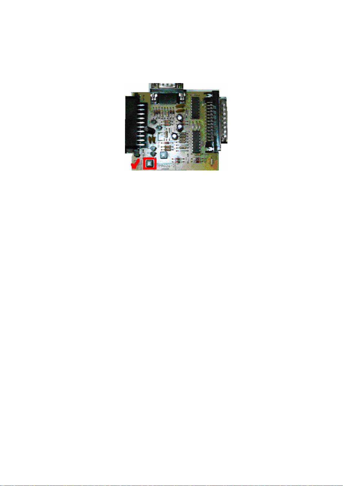
VCTI Microcontroller Programming
***Firstly, push the switch1 button that is located on the programming card. (switch2
have to be off)
*** Please turn on the TV . After the TV image was visible, press “menu” and “1905”
by using remote control. Please connect both of the scart connectors (TV scart1
connector and programming card connector) by using scart cable. Please connect
both of the parallel port connectors (computer parallel port connector and
programming card connector) by using parallel port cable. Then, please open the
Micronas VCTI49XYI programming software interface.


*** After this folder was opened, a window will appear as below. Please choose
window, find window options in turn in order. Please write “bootloader” in selected
window (or click the TVT button as below), searching will start automatically. At
the end of the searching process, please double click to bootloader.bat.


*** Please click over to the “bootloader” icon for prepearing to loading. TV will oto
stand-by mode if bootloder process was achived. And below window will appear
on the tv screen.

***If bootloader process was failed by using this button, another process is getting to
bootloader mode manually by using below window.
***After bootloader process, please pass to the reading process.

***After the reading process, bootloader version will come as 21 or 22 that depends
on bootloader version of IC.
***After that, please click to “erase flash” button that was determined by yellow color
as below.

***Set the options as to=0x7FFF and reclen=16. Please choose the path of binary file
by using “NAME” part.
*** As finally click to over of the Load BinÆ Flash icon .Loading will be started
automatically.

(!) IMPORTANT NOTE (1): If there is a problem as fast loading. Please follow the
steps;
*** Please open the File → Preferences → LPT Preferences. Below window will appear.
***Please make Delay = 10
(!) IMPORTANT NOTE (2): If there is a problem during bootloader process or there is
a message as “No Acknowledge From The Slave”, Please apply the following steps;
-Please turn off the TV.
-Please open the bootloader file.
-Please press bootloader icon and turn on the TV at the same time. You have to do
these process at same time.
(!) INITING NVM:
For initing the NVM (E2PROM);
-Please turn on the TV.
-Please press -turn in order- “menu”,”4”,”7”,”2”,”5”.
-You will see service menu that located on the screen.
-You will see init NVM option at the service menu.
-Get the string of this as INIT NVMÆYES.
-Turn off the TV.
-Thus, Inıt nvm process is over.

E2PROM READING AND WRITING
*** Firstly, push the switch2 button that is located on the programming card. (switch1
have to be off)
*** Please turn on the TV . After the TV image was visible, press “menu” and “2045”
by using remote control. Please connect both of the scart connectors (TV scart1
connector and programming card connector) by using scart cable. Please connect
both of the serial port (RS232) connectors (computer serial port (RS232)connector
and programming card connector) by using serial port cable. Then, please open
the Ponyprog programming software interface.

*** Please control some adjustments.
*** COM port settings can be made from set-up menu.
 Loading...