


CONTENTS
Safety Precautions ........................................................................................................................................... 2
TV Set switched off ........................................................................................................................................... 2
Measurements ................................................................................................................................................. 2
PERI -TV SOCKET............................................................................................................................................ 2
SCART 1, SCART 2 .......................................................................................................................................... 2
INTRODUCTION .............................................................................................................................................. 2
SWITCH-MODE POWER SUPPLY (TDA 16846) .............................................................................................. 3
IF PART (TDA 4470/72) ..................................................................................................................................... 3-4
TUNER ............................................................................................................................................................. 4-5
SAW FILTERS ................................................................................................................................................... 5
DIGITAL TV SOUND PROCESSING (MSP 3410D) .......................................................................................... 5-6
DOLBY PRO LOGIC PROCESSOR IC (DPL 3519A) ....................................................................................... 6-7
HEADPHONE OUTPUT (TDA 1308) ................................................................................................................ 7
VIDEO OUTPUT (TDA 7265) ............................................................................................................................ 7-8
VIDEO INPUT AND OUTPUT SOURCE SWITCHING (TEA 6415) ................................................................... 8
VIDEO OUTPUT AMPLIFIER STAGE (TDA 6111Q) ........................................................................................... 8-9
VERTICAL OUTPUT STAGE (TDA 9379FA) ...................................................................................................... 9
TTEXT CONTROLLER (SDA 5550M) ............................................................................................................... 9-10
SERIAL ACCESS 32K EEPROM (24L32-W) .................................................................................................... 10-11
EPROM (M27W401) ......................................................................................................................................... 11
100Hz FEATURE BOX ...................................................................................................................................... 11
VPC32X5 (VIDEO PROESSOR) ................................................................................................................. 11
CIP3250 ...................................................................................................................................................... 12-13
SDA9400 ..................................................................................................................................................... 13-14-15
DDP3310 .................................................................................................................................................... 15-16
AK41 CHASSIS MANUAL ADJUSTMENTS PROCEDURE............................................................................... 17
PRELIMINARY ............................................................................................................................................. 17
SYSTEM VOLTAGE AJUSTMENT ................................................................................................................ 17
AFC ADJUSTMENT ..................................................................................................................................... 17
FOCUS ADJUSTMENT ................................................................................................................................17
SCREEN ADJUSTMENT ............................................................................................................................. 17
IF ADJUSTMENT FOR LMODE ................................................................................................................... 17
AK41 CHASSIS PRODUCTION MODE ADJUSTMENTS PROCEDURE ......................................................... 18
PRELIMINARY ............................................................................................................................................. 18
HORIZONTAL AND VERTICAL GEOMETRY ALIGNMENTS ........................................................................ 18
V-SHIFT ....................................................................................................................................................... 18
V-SIZE.......................................................................................................................................................... 18
H-SHIFT ...................................................................................................................................................... 18
H-SIZE ......................................................................................................................................................... 18
S-COR ......................................................................................................................................................... 18
LINRT .......................................................................................................................................................... 18
ANGLE ........................................................................................................................................................ 18
BOW ... ........................................................................................................................................................ 1 8
TRPEZ ......................................................................................................................................................... 18
PARAB ......................................................................................................................................................... 18
U.COR ......................................................................................................................................................... 19
L.COR ......................................................................................................................................................... 1 9
VIDEO ALIGNMENTS ........................................................................................................................................ 19
RGn, GGn, BGn,:WHITE BALANCE ADJUSTMENT .................................................................................... 19
RRf, GRf, BRf .............................................................................................................................................. 19
YDF . ........................................................................................................................................................... 19
AGC . .......................................................................................................................................................... 19
TLAN ........................................................................................................................................................... 19
APS . ........................................................................................................................................................... 19
T_T ............................................................................................................................................................ 19
T_P ............................................................................................................................................................ 19
EXT3 ............................................................................................................................................................ 19
CLT ............................................................................................................................................................ 19
SERVICE ALIGNMENTS ................................................................................................................................... 20
IMPORTANT ................................................................................................................................................ 20
ADJUSTMENTS GROUOP.......................................................................................................................... 20
OPTIONS GROUP ...................................................................................................................................... 2 0
SYSTEM GROUP ........................................................................................................................................ 20
GENERAL BLOCK DIAGRAM OF CHASSIS AK41 ........................................................................................... 21
CIRCUIT DIAGRAMS ........................................................................................................................................ 22
1
DO NOT CHANGE ANY MODULE UNLESS THE SET IS SWITCH OFF
The mains supply side of the switch mode power supply transformer is live.
Use an isolating transformer.
The receivers fulfill completely the safety requirements.
Safety precautions:
Servicing of this TV should only be carried out by a qualified person.
- Components marked with the warning symbol on the circuit diagram are critical for safety and must only be replaced
with an identical component.
- Power resistor and fusable resistors must be mounted in an identical manner to the original component.
- When servicing this TV, check that the EHT does not exceed 26kV.
TV Set switched off:
Make short-circuit between HV-CRT clip and CRT ground layer.
Short C804 (150mF) before changing IC802 or other components in primary side of SMPS.
Measurements:
Voltage readings and oscilloscope traces are measured under following conditions.
Antenna signal 60dB from colourbar generator. (100% white, 75% colour saturation)
Brightness, contrast, colour set for a normal picture.
Mains supply, 220VAC, 50Hz.
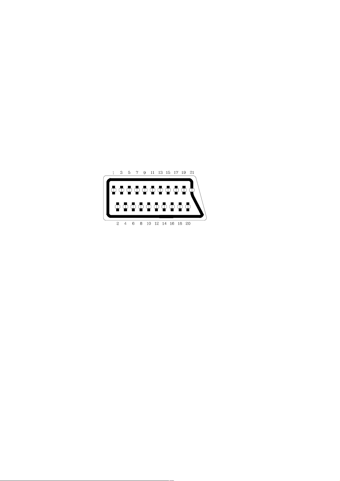
PERI-TV SOCKET
SCART 1 (SC050) SCART 2 (SC051)
1 Audio right output 0.5Vrms / 1K 1 Audio right output 0.5Vrms / 1K
2 Audio right input 0.5Vrms / 10K 2 Audio right input 0.5Vrms / 10K
3 Audio left output 0.5Vrms / 1K 3 Audio left output 0.5Vrms / 1K
4 Ground AF 4 Ground AF
5 Ground Blue 5 Ground Blue
6 Audio left input 0.5Vrms / 10K 6 Audio left input 0.5Vrms / 10K
7 Blue input 0.7Vpp / 75ohm 7 Blue input 0.7Vpp / 75ohm
8 AV switching input 0-12VDC /10K 8 AV switching input 0-12VDC /10K
9 Ground Green 9 Ground Green
10 - 10 11 Green input 0.7Vpp / 75ohm 11 12 - 12 13 Ground Red 13 Ground Red
14 Ground Blanking 14 Ground Blanking
15 Red input 0.7Vpp / 75ohm 15 16 Blanking input 0-0.4VDC, 1-3VDC / 75ohm 16 17 Ground CVS output 17 Ground CVS output
18 Ground CVS input 18 Ground CVS input
19 CVS output 1Vpp / 75ohm 19 CVS output 1Vpp / 75ohm
20 CVS input 1Vpp / 75ohm 20 CVS input 1Vpp / 75ohm
21 Ground 21 Ground
INTRODUCTION
11Ak41 is a 100Hz flicker free colour television capable of driving 284:3/16:9, 334:3 and 294:3 real flat picture tubes.
The chassis is capable of operation in PAL, SECAM, NTSC (playback) colour standards and multiple transmission standards
as B/G, D/K, I/I, and L/L´.
Sound system output is supplying 12W (10%THD) for left, right and center outputs of 8ohm speakers, and 2 x 7W for surround
outputs of 2 x 4ohm speakers, connected in series.
TV supports the level 1.5 teletext standard. It is possible to decode transmissions including high graphical data.
The chassis is equipped with one full EuroScart, one other SCART for AV input/output, one front-AV input, one back-AV
output, one headphone output, one SVHS input (via SCART and SVHS connector), one VGA input, two external speaker
outputs (left and right), one centre speaker output, and one surround speaker output for two speakers in series.
2

SWITCH-MODE POWER SUPPLY (TDA16846)
A SMPS transformer controlled by the IC TDA16846, which is designed for driving, controlling, and protecting switching
transistor, provides the DC voltages required at various parts of the chassis. SMPS generates the necessary 3.3V and 2.5V
supplies for the micro-controller, 130V supply for the FBT, +/-16V supply for the audio amplifier, which are active in stand-by
and 8V, 12V and 5V supplies for other different parts of the chassis.
When the TV is switched on, a reference voltage is provided to TDA16846 and the start-up operation occurs, then TV
enters into the stand-by position.
Two optocouplers are used to control the regulation of line voltage and stand-by power consumption. There are two regulation circuits, one in primary side and one in secondary side. The primary regulation circuit provides a control voltage to pin3
of the IC. Secondary regulation circuit produces a control voltage according to the changes in 130V DC voltage, via an
optocoupler (SFH617A) to pin4 of the IC.
During the switch on period of the transistor, energy is stored in the transformer. During the switch off period energy is fed
to the load via secondary winding. By varying switch-on time of the power transistor, it controls each portion of energy
transferred to the second side such that the output voltage remains nearly independent of load variations. At the same time,
the supply voltages 12V, 8V, 5V are stabilised by the series regulators.
Features:
n Line Current Consumption with PFC
n Continuous Frequency Reduction with Decreasing Load
n Stable and Adjustable Stand-by Frequency
n Very Low Start-up Current
n Soft-Start for Quiet Start-up
n Adjustable and Voltage Dependent Ringing Suppression Time
n Synchronization and Fixed Frequency Facility
n Over- and Under-voltage Lockout
n Switch Off at Mains Under-voltage
n Mains Voltage Dependent Fold Back Point Correction
n Low Power Consumption
n Free usable Fault Comparators
Pinning:
1. OTC Off Time Circuit
2. PCS Primary Current Simulation
3. RZI Regulation and Zero Crossing Input
4. SRC Soft-Start and Regulation Capacitor
5. OCI Opto Coupler Input
6. FC2 Fault Comparator 2
7. SYN Synchronization Input
8. N. C. Not Connected
9. REF Reference Voltage and Current
10. FC1 Fault Comparator 1
11. PVC Primary Voltage Check
12. GND Ground
13. OUT Output
14. VCC Supply Voltage
IF PART (TDA4470/72)
The TDA44XX is an integrated bipolar circuit for multistandard video/sound IF (VIF/SIF) signal processing in TV/VCR
and multimedia applications. The circuit processes all TV video IF signals with negative modulation (e.g., B/G standard),
positive modulation (e.g., L standard) and the AM, FM/NICAM sound IF signals. Active carrier generation by FPLL (frequency phase-locked loop) is the principle for true synchronous demodulation. VCO circuit is operating on picture carrier
frequency, the VCO frequency is switchable for L´-mode. AFC without external reference circuit is alignment-free and
polarity of the AFC curve is switchable. VIF-AGC for negative modulated signals operates on peak sync detection principle
and for positive modulation on peak white / black level detection principle. Tuner AGC is adjustable with determining take
over point. It has alignment-free quasi-parallel sound (QPS) mixer for FM/NICAM sound IF signals. Intercarrier output sound
is gain controlled (necessary for digital sound processing). AM-demodulator is completely alignment-free with gain controlled AF output. Operation of the AM demodulator and QPS mixer (for NICAM-L stereo sound is parallel. TDA4472 is used for
negative modulation and TDA4470 is used for both negative and positive modulation.
3

Features:
n 5V supply voltage; low power consumption
n Active carrier generation by FPLL principle (frequency-phase-locked-loop) for true synchronous demodulation
n Very linear video demodulation, good pulse response and excellent intermodulation figures
n VCO circuit is operating on picture carrier frequency, the VCO frequency is switchable for the L mode
n Alignment-free AFC without external reference circuit, polarity of the AFC curve is switchable
n VIF-AGC for negative modulated signals (peak sync detection) and for positive modulation
(peak white/black level detector).
n Tuner AGC with adjustable take over point
n Alignment-free quasi parallel sound (QPS) mixer for FM/NICAM sound IF signals
n Intercarrier output signal is gain controlled (necessary for digital sound processing)
n Complete alignment-free AM demodulator with gain controlled AF output
n Separate SIF-AGC with average detection
n Two independent SIF inputs
n Parallel operation of the AM demodulator and QPS mixer (for NICAM-L stereo sound)
n Package and relevant pinning is compatible with the single standard version TDA 4472; simplifies the design of
an universal IF module
Pinning:
1. Input sensitivity, RMS value : 80mVrms
2. Input sensitivity, RMS value : 80mVrms
3. SIF Input selector switch : 2.0 V
4. Ground
5. IF gain control range : 65dB
6. Input sensitivity, RMS value : 80mVrms
7. Input sensitivity, RMS value : 80mVrms
8. IF gain control range : 65dB
9. Ground
10. Available tuner-AGC current : 2mA
11. Available tuner-AGC current : Min : 0.3V Max : 13.5V
12. Video output : Min : 1.8V Max : 2.2V
13. Standard switch : Min : 0V Max : 0.8V
14. L switch : Min : 0V Max : 3.0V
15. IF gain control range : 65dB
16. Ground
17. Internal reference voltage
18. FPLL and VCO : Min : 1mA Max : 4mA
19. AFC switch : Min : 0V Max : 0.8V
20. FPLL and VCO : Min : 1mA Max : 4mA
21. FPLL and VCO : Min : 1mA Max : 4mA
22. AFC output : 0.7 mA/kHz
23. DC supplay : Min : 4.5V Max : 9.0V
24. DC output voltage : 2V
25. AF output-AM : 2.2V
26. FPLL and VCO : Min : 1mA Max : 4mA
27. Input sensitivity, RMS value : 80mVrms
28. Input sensitivity, RMS value : 80mVrms
TUNER
The hardware and software of the TV is suitable for tuners, supplied by different companies, which are selected from the
Service Menu. These tuners can be combined VHF, UHF tuners suitable for CCIR systems B/G, H, L, L´, I/I´, and D/K.
The tuning is available through the digitally controlled I²C bus (PLL). Below you will find info on one of the Tuners in use.
General description of UV1316:
The UV1316 tuner belongs to the UV 1300 family of tuners, which are designed to meet a wide range of applications. It is a
combined VHF, UHF tuner suitable for CCIR systems B/G, H, L, L, I and I. The low IF output impedance has been designed
for direct drive of a wide variety of SAW filters with sufficient suppression of triple transient.
Features of UV1316:
n Member of the UV1300 family small sized UHF/VHF tuners
n Systems CCIR: B/G, H, L, L, I and I; OIRT: D/K
n Digitally controlled (PLL) tuning via I2C-bus
n Off-air channels, S-cable channels and Hyperband
n World standardised mechanical dimensions and world standard pinning
n Compact size
n Complies to CENELEC EN55020 and EN55013
4

Pinning:
1. Gain control voltage (AGC) : 4.0V, Max:4.5V
2. Tuning voltage
3. I²C-bus address select : Max:5.5V
4. I²C-bus serial clock : Min:-0.3V, Max:5.5V
5. I²C-bus serial data : Min:-0.3V, Max:5.5V
6. Not connected
7. PLL supply voltage : 5.0V, Min:4.75V, Max:5.5V
8. ADC input
9. Tuner supply voltage : 33V, Min:30V, Max:35V
10. Symmetrical IF output 1
11. Symmetrical IF output 2
SAW FILTERS
K9453: Two channels switchable sound IF saw filter of BG, DK, I, L systems for input channel 2 and of L´
system for input channel 1.
K3953: Two channel switchable video IF saw filter of BG, DK, I, L systems for input channel 2 and of L´
system for input channel 1.
J3950: Video IF saw filter for I system
DIGITAL TV SOUND PROCESSING
MSP3410D
The MSP3410D is an I2C controlled single-chip multistandard sound processor for applications in analog and digital TV
sets. The full TV sound processing, starting with analog sound IF signal-in, down to processed analog AF-out is
performed in a single-chip covering all European TV-standards. It is designed to simultaneously perform digital
demodulation and decoding of NICAM-coded TV stereo sound, as well as demodulation of FM-mono TV sound and two
FM systems according to the German or Korean terrestrial specs. It is also possible to do AM-demodulation according to
the SECAM system. There is AGC for analog inputs: 0.14 - 3Vpp. All demodulation and filtering is performed on chip and
is individually programmable. All digital NICAM standards (B/G, L, and I) are realised. Only one crystal clock (18.432Mhz)
is necessary. External capacitors at each crystal pin to ground are required. They are necessary for tuning the open-loop
frequency of the internal PLL and for stabilising the frequency in closed-loop operation. The higher the capacitors, the
lower the clock frequency result. The nominal free running frequency should match the centre of the tolerance range
between 18.433 and 18.431Mhz as closely as possible. By means of standardised I2S interface, additional feature
processors (DPL35xx, Dolby Prologic processor for this chassis) can be connected to the IC.
I2S bus interface consists of five pins:
I2S_DA_IN12 for input four channels (two channels per line) per sampling cycle (32Khz).
I2DA_OUT, for output, two channels per sampling cycle (32KHz).
I2S_CL, for timing of the transmission of I2S serial data, 1.024Mhz.
I2S_WS, for the word strobe line defining the left and right sample.
Features:
n 5-band graphic equalizer (as in MSP3400C)
n Enhanced spatial affect (pseudo stereo / base-width enlargement as in MSP3400C)
n Headphone channel with balance, bass treble, loudness
n Balance for loudspeaker and headphone channels in dB units (optional)
n Additional pair of D/A converters for SCART2 out
n Improved over-sampling filters (as in MSP 3400C)
n Additional SCART input
n Full SCART in/out matrix without restrictions
n SCART volume in dB units (optional)
n Additional I²S input (as in MSP 3400C)
n New FM-identification (as in MSP 3400C)
n Demodulator short programming
n Auto-detection for terrestrial TV-sound standards
n Precise bit-error rate indication
n Automatic switch from NICAM to FM/AM or vice versa
n Improved NICAM synchronisation algorithm
n Improved carrier mute algorithm
n Improved AM-demodulation
n ADR together with DRP 3510A
n Dolby Pro Logic together with DPL 35xx A
n Reduction of necessary controlling
n Less external components
n Significant reduction of radiation
5

Pinning:
1. ADR wordstrobe 35. Analog Shield Ground 1
2. Not connected 36. Scart input 3 in right
3. ADR data output 37. Scart input 3 in left
4. I²S 1 data input 38. Analog Shield Ground 4
5. I²S data output 39. Scart input 4 in, right
6. I²S wordstrobe 40. Scart input 4 in, left
7. I²S clock 41. Not connected
8. I²S data 42. Analog reference voltage high voltage part
9. I²S clock 43. Analog ground
10. Not connected 44. Volume capacitor MAIN
11. Standby (low-active) 45. Analog power supply 8.0V
12. I²C Bus address select 46. Volume capacitor AUX
13. Digital control output 0 47. Scart output 1, left
14. Digital control output 1 48. Scart output 1, right
15. Not connected 49. Reference ground 1 high voltage part
16. Not connected 50. Scart output 2, left
17. Not connected 51. Scart output 2, right
18. Audio clock output 52. Analog Shield Ground 3
19. Not connected 53. Not connected
20. Crystal oscillator 54. Not connected
21. Crystal oscillator 55. Not connected
22. Test Pin 56. Analog output MAIN, left
23. IF input 2 (if ANA_IN1+is used only, connect 57. Analog output MAIN, right to AVSS with 50 pF capacitor) 58.
24. IF common 58. Reference ground 2 high voltage part
25. IF input 1 59. Analog output AUX, left
26. Analog power supply +5V 60. Analog output AUX, right
27. Analog ground 61. Power-on-reset
28. Mono input 62. Not connected
29. Reference voltage IF A/D converter 63. Not connected
30. Scart input 1 in, right 64. Not connected
31. Scart input 1 in, left 65. I²S2-data input
32. Analog Shield Ground 2 66. Digital ground
33. Scart input 2 in, right 67. Digital power supply +5V
34. Scart input 2 in, left 68. ADR clock
DOLBY PRO LOGIC PROCESSOR IC
DPL3519A
The IC DPL3519A processor family is designed to decode Dolby encoded surround sound. The IC integrate the complete
Dolby Surround Pro Logic decoding on chip without any necessary external circuitry. It designed as a coprocessor of the
MSP34xx family.
It gets digitised sound from the audio processor IC MSP3410D for both C (centre) and S (surround) channels, and for
both L (left) and R (right) channels. The analog L and R outputs are supplied by MSP3410D, while the analog S and C
outputs are supplied by the DPL33519A.
Two I2S busses obtain synchronisation between the MSP and DPL :
I2S_CL; for timing of the transmission of I2S serial data 1.024Mhz and I2S_WS; The word strobe line defining the left
and right sample at 32Khz. The IC is also I2C bus controlled to select the sound feature (Stereo, 3D-Phonic and Dolby
Pro Logic).
Pinning:
1. Not connected 16. Not connected
2. Not connected 17. Not connected
3. Not connected 18. Audio clock output
4. I2S1 data input 19. Digital control input
5. I2S1 data output 20. Crystal oscillator
6. I2S wordstrobe 21. Crystal oscillator
7. I2S clock 22. Test pin
8. I2C data 23. Not connected
9. I2C clock 24. Not connected
10. Not connected 25. Not connected
11. Standby (low-active) 26. Analog power supply +5 V
12. I2C-Bus address select 27. Analog ground
13. Digital control IO 0 28. Mono input
14. Digital control IO 1 29. Reference voltage
15. Not connected 30. Scart input 1 in, right
6

31. Scart input 1 in, left 50. Scart output 2, left
32. Analog Shield Ground 1 51. Scart output 2, right
33. Scart input 2 in, right 52. Analog Shield Ground 3
34. Scart input 2 in, left 53. Not connected
35. Analog Shield Ground 2 54. Not connected
36. Scart input 3 in, right 55. Not connected
37. Scart input 3 in, left 56. Analog output Channel 1, left
38. Analog Shield Ground 4 57. Analog output Channel 1, right
39. Not connected 58. Reference ground 2 high voltage part
40. Not connected 59. Analog output Channel 2, left
41. Not connected 60. Analog output Channel 2, right
42. Analog reference voltage high voltage part 61. Power-on-reset
43. Analog ground 62. Not connected
44. Volume capacitor Channel1 63. Not connected
45. Analog power supply 8.0 V 64. I2S2-data output
46. Volume capacitor Channel 2 65. I2S2-data input
47. Scart output 1, left 66. Digital ground
48. Scart output 1, right 67. Digital power supply +5 V
49. Reference ground 1 high voltage part 68. Not connected
HEADPHONE OUTPUT
TDA1308
The TDA1308 is an integrated class AB stereo headphone driver. It gets its input from two analog audio outputs (DACA_L
and DACA_R) of MSP3410D. The gain of the output is adjustable by the feedback resistor between the inputs and outputs.
Features:
n Wide temperature range
n No switch ON/OFF clicks
n Excellent power supply ripple rejection
n Low power consumption
n Short-circuit resistant
n High performance - high signal-to-noise ratio
- high slew rate
- low distortion
n Large output voltage swing
Pinning:
1. Output A (Voltage swing) : Min : 0.75V, Max : 4.25V
2. Inverting input A : Vo(clip) : Min : 1400mVrms
3. Non-inverting input A : 2.5V
4. Ground
5. Non-inverting input B : 2.5V
6. Inverting input B : Vo(clip) : Min : 1400mVrms
7. Output B (Voltage swing) : Min : 0.75V, Max : 4.25V
8. Positive supply : 5V, Min : 3.0V, Max : 7.0V
AUDIO OUTPUT
TDA7265
The TDA7265 is a 25W+25W stereo sound amplifier with mute/stand-by facility. STPA control signal coming from microcontroller
(when it is at high level) activates the mute function. IC is muted when mute port is at low level. Two stereo audio signals
coming from audio module is injected to the inputs of the IC and a power of 12Wrms (10%) is obtained. An external popnoise circuitry pulls AF inputs of the IC in order to eliminate pop noise when TV is turned on or off via mains supply
connection. It is possible to adjust the gain of the amplifiers by feedback external resistors.
Features:
n Wide supply voltage range (up to 50V ABS Max.)
n Split supply
n High output power: 25+25 W @ TDA = 10%, RL = 8ohm, VS = ±20V
n No pop at turn-on / off
n Mute (pop free)
n Stand-By feature (low IQ)
n Few external components
n Thermal overload protection
n Adjustable gain via an external resistor
7
 Loading...