

Page 1

VESTAX CORPORATION
1-18-6 Wakabayashi, Setagaya-ku, Tokyo 154-0023 Japan
Phone:03-3412-7011 Fax:03-3412-7013
Web:www.vestax.jp
VESTAX America
2750N. 29th Avenue, Suite 115, Hollywood, FL33020.
Phone:954-926-6622 Fax:954-926-3304
Web:www.vestaxdj.com
VESTAX(Europe)Ltd.
Unit 5 Riverwey Industrial Park Alton, Hampshire GU34 2QL England, U.K
Phone:(0)1420-83000 Fax:(0)1420-80040
Web:www.vestax.co.uk
Vestax Technical Center of America
8489 W.Third Street Ste.1044 Los Angeles CA 90048
Phone:1-323-801-2111 Fax:1-323-801-2112
Vestax Europe Technical Support
Rheinstr.213 D-53332 Bornheim Germany
Phone:49(0)2222-95-23-72 Fax:49(0)2222-95-23-74
OWNER'S MANUAL
Professional Mixing Controller
Page 2
1
CONGRATULATIONS
!
The lightning flash with arrowhead symbol,within an equilateral triangle,is intended to
alert the user to the presence of uninsulateddangerous voltagewithin the product's
enclosure that may be of sufficient magnitude to consitute a risk of electric shock to persons.
The exclamation point within an equilateral triangle is intended to alert the user to the presence
of important operating and maintenance(servicing)instructions in the literature accompanying
the appliance.
T0 REDUCE THE RISK 0F FIRE 0R ELECTRlC SHOCK,DO NOT
EXPOSE THIS APPLIANCE T0 RAIN 0R M0ISTURE.
CAUTl0N: TO REDUCE THE RlSK OF ELECTRlC SHOCK
DO NOT REMOVE COVER( OR BACK)
NO USER-SERVICEABLE PARTS INSIDE
REFER SERVlCING T0 QUALIFIED SERVlCE PERSONNEL
CAUTION
RISK OF ELECTRIC SHOCK DO NOT OPEN
CONTENTS
CAUTION
1
IMPORTANT SAFEGUARDS
2
FEATURES
3
FUNCTIONS
4
PROGRAM INPUT SECTION
5
HOW TO CHANGE THE FADER UNIT
6
MIC.MASTER SECTION
7
REAR PANEL SECTION
8
CONNECTIONS 9
SPECIFICATIONS 10
The PCV-175 is a high profile mixer designed to meet various professional requirements of
today's dance music DJs. Please read this owner's manual carefully before you start to use your
mixer, so that you will fully understand all of the special features and enjoy the full use of the
product.
Page 3

2
1. Read instructions-All the safety and operating
instructions should be read before the appliance
is operated.
2. Retain instructions-The safety and operating
instructions should be retained for future
reference.
3. Heed Warnings-All warnings on the appliance
and in the operating instructions should be
adhered to.
4. Follow Instructions-All operating and use
instructions should be followed.
5. Cleaning-Do not use liquid cleaners or aerosol
cleaners. Use a damp cloth for cleaning.
6. Attachments-Do not use attachments not
recommended by the product manufacturer as
they may cause hazards.
7. Water and Moisture-Do not use this product near
water-for example, near a bath tub, wash bowl,
kitchen sink, or laundry tub, in a wet basement,
or near a swimming pool, and the like.
8. Accessories-Do not place this product on an
unstable cart, stand, tripod, or table. The product
may fall, causing serious injury to a child or
adult, and serious damage to the appliance. Use
only with a cart,. stand, tripod, bracket, or table
recommended by the manufacturer, or sold with
product. Any mounting of the appliance should
follow the manufacturer's instructions, and
should use a mounting accessory recommended
by the manufacturer.
9. This product should never be placed near or over
a radiator or heat register. This product should
not be placed in a built-in installation such as a
bookcase or rack unless proper ventilation is
provided or the manufacturer's instructions have
been adhered to.
10. Power sources-This product should be operated
only from the type of power source indicated on
the marking label. If you are not sure of the type
of power supply to your home, consult your
appliance dealer or local power company.
11. Lightning-For added protection of this product
during a lightning storm, or when it is left
unattended and unused for long periods of time,
unplug it from the wall outlet. This will prevent
damage to the product due to lightning and
power-line surges.
12. Overloading-Do not overload wall outlets and
extension cords as this can result in a risk of fire
or electric shock.
13. Object and Liquid Entry-Never push objects of
any kind into this product through openings as
they may touch dangerous voltage points or
short-out parts that could result in a fire or
electric shock. Never spill liquid of any kind on
the product.
14. Servicing-Do not attempt to service product
yourself as opening or removing covers may
expose you to dangerous voltage or other
hazards. Refer all servicing to qualified
personnel.
IMPORTANT SAFEGUARDS
READ BEFORE OPERATING EQUIPMENT
This product was designed and manufactured to meet
strict quality and safety standards. There are, however,
some installation and operation precautions which you
should be particularly aware of.
Page 4

3
15. Damage Requiring Service-Unplug this product
from the wall outlet and refer servicing to
qualified service personnel under the following
conditions:
a. When the power-supply cord or plug is
damaged.
b. If liquid has been spilled or objects have fallen
into the product.
c. If the product has been exposed to rain or
water.
d. If the product dose not operate normally by
following the operating instructions. Adjust
only those controls that are coverd by the
operating instructions as an improper
adjustment of other, controls may result in
damage and will often require extensive work
by a qualified technician to restore the product
to its normal operation.
e. If the product has been dropped or cabinet has
been damaged.
f. When the product exhibits a distinct change in
performance this indicates need for service.
16. Replacement Parts-When replacement parts are
required, be sure the service technician has used
replacement parts specified by the manufacturer
or have the same characteristics as the original
parts. Unauthorized substitutions may result in
fire, electric shock or other hazards.
17. Safety Check-Upon completion of any service or
repairs to product, ask the service technician to
perform safety checks to determine that the
product is in proper operating condition.
18. Carts and Stands-The appliance should be used
only with a cart stand that is recommended by
manufacturer.
19. An appliance and cart combination should be
moved with care. Quick stops, excessive force,
and uneven surfaces may cause the appliance
and cart combination to overturn.
FEATURES
● 60mm long faders are provided for 3 program
channels. More sensitive control can be
achieved for Techno/Trance mixing.
● Effect send switch is equipped on each input
channel for effect parformance. The effect send
and return level controls are provided in the
master section.
● P.F.L. (pre fader listen) switch is provided for pre
fader monitoring.
● The input levels are monitored by over load
indicator.
● Four mic input levels are provided. The main mic
can be assigned to program channel 2 for full
control. The other tree mics are mixed with
individual level control, 2 band EQ, effect send
and P.F.L.
● Ten segment LED level meter is provided for
careful level check.
● A powerful 3 band EQ with +6/-24dB range is
provided along with the instant out switch on
each band. More sensitve and drastic control can
be achieved for Techno/Trans mixing.
● The new PCV-175 features removable flat panel
that covers all screws etc., that will impede fast
mixing. The panel is removed for crossfader and
inputfaders replacement.
● New suprior grade crossfader (CF-PCV) fittde to
PCV-175 enebling super smooth operation
torether with long life.
Page 5
4
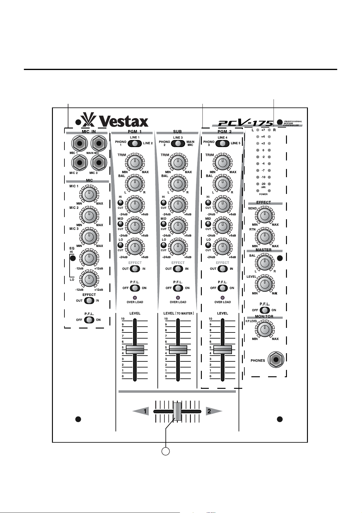
MASTER
SECTION
PROGRAM
INPUT SECTION
MIC INPUT
SECTION
12
FUNCTIONS
Page 6
5
PROGRAM INPUT SECTION
1
8
9
10
2
3
4
5
6
11
7
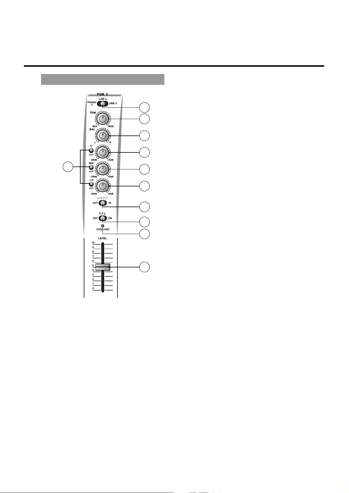
○5EQUALIZER
(MID 1KHz +6dB〜-24dB)
Adjusts the MID frequeny level of each PGM
channel.
○6EQUALIZER
(LOW 80Hz +6dB〜-24dB)
Adjusts the LOW freguency level for each PGM
channel.
○7EQ CUT SWITCH ( HI, MID, LOW )
Cuts off the each frequency range by 24dB. The
EQUALIZER volume dose not function when this
switch is set to "CUT".
○8EFFECT SWITCH
Used to send the signal to the external effect processor
connected to the effect SEND/RETURN.
○9P.F.L.. SWITCH
Used to send the signal from the PGM channel to the
monitor section for headphone monitoring.
○10OVERLOAD INDICATOR
Lights when input level is over.
○11INPUT FADER
This is a detachable fader for the ease of
replacement. Replace with IF-175 when it is worn
out.
○12CROSS FADER
When the input level of PGM1 and PGM2 are
properly set, PGM1 will be heard with the cross
fader set to the left side. PGM2 will be heard with
the cross fader set to the right side. When the cross
fader is set in the center, both programs will be
heard. This is detachable fader for the ease of
replacement witrh "CF-PCV" when it is worn out.
○1INPUT SELECTOR
Used to select input (2 line or 1 phono) to be sent to
each PGM channel.
○2TRIM CONTROL
Adjusts the input level of each channel. Set INPUT
FADER to 7-8 position, adjust the TRIM CONTROL
so that the sufficient signal is fed without distortion.
○3BALANCE CONTROL
Adjusts the stereo balance for each PGM channel.
Can be used for adjusting the unbalanced stereo
image. Clockwise rotation from center position
increases the volume of R over L channel. A counter
clockwise rotation increases the volume of L
channel over R.
○4EQUALIZER
(HI 10Hz +6dB〜-24dB)
Adjusts the HI frequeny level of each PGM channel.
Page 7
Driver
6
HOW TO CHANGE THE FADER UNIT
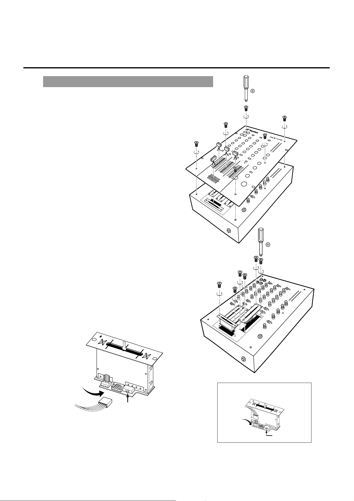
Insert the
multi-cable connector
Set switch to "PCV" position.
■HOW TO REMOVE THE TOP PANEL
○
1
Remove each fader knobs and 6 screws which
fix the top panel.
○
2
Remove the top panel.
■HOW TO CHANGE THE FADER UNIT
○
1
Remove the screws on the fader panel.
○
2
Remove the fader unit from position in mixer.
○
3
Carefully remove the multi-cable connector from
fader unit.
○
4
Attach multi-cable connector to new fader unit.
○
5
Position the fader unit carefully and secure with
screws.
PMC CONNECTOR
Set switch to "PMC" position
CF-PCV For
PMC SERIES
( PMC05ProII, PMC06ProA, etc)
Driver
Page 8
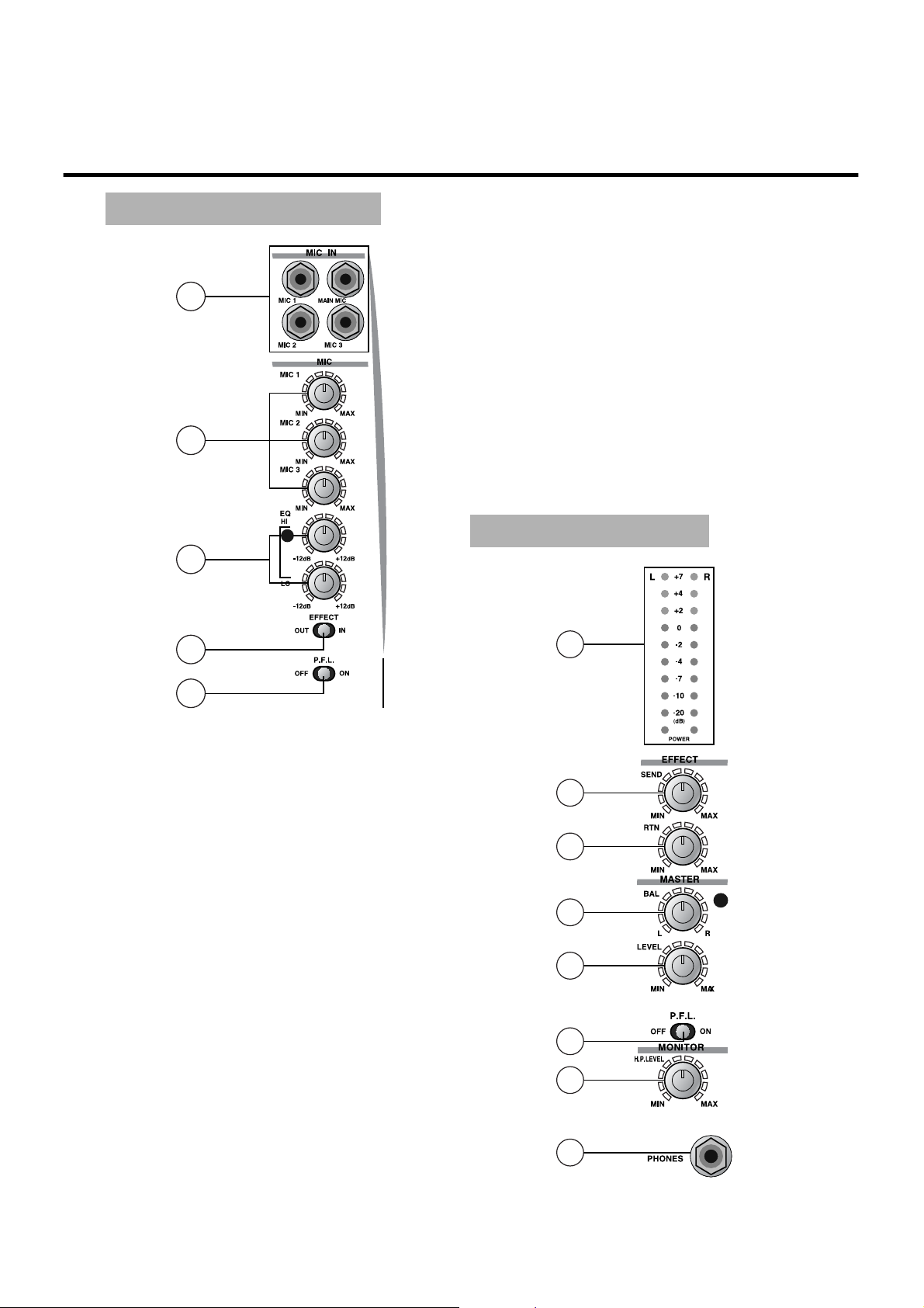
7
MASTER SECTION
19
20
21
22
24
25
18
23
○18MASTER OUT LEVEL METER
Indicate the signal level of the line output. The
lowest segment lights when the power is on.
○19EFFECT SEND LEVEL
Used to adjust the output level from EFFECT SEND
JACK.
○20EFFECT RETURN LEVEL
Used to adjust the input level from EFFECT
RETURN JACK.
○21MASTER BALANCE VOLUME
Adjust the signal balance between left and right of
the master output.
○22MASTER LEVEL VOLUME
Adjust the signal level of the master output.
○23P.F.L. SWITCH
Used to send the master output signal to the monitor
section for the headphone monitoring.
○24HEADPHONE LEVEL
Adjusts the headphone monitor level.
○25HEADPHONE JACK
Connect the headphones with the inpedance of 8ohm
to 600 ohm.
○13MIC INPUT JACK(MAIN MIC, MIC1〜3)
Input jacks for MAIN MIC, MIC1, MIC2 and
MIC3.
○14MIC LEVEL
Adjusts the input level of MIC1, 2 and 3.
○15MIC EQUALIZER(HI,LOW)
Adjusts the HI and LOW frequency level of MIC1,
2 and 3.
○16EFFECT SWITCH
Used to send the signal to the external effect
processor connected to the effect SEND/RETURN.
○17P.F.L. SWITCH
Used to send the signal from the mic channel to the
monitor section for headphone monitoring.
15
13
14
16
17
MIC INPUT SECTION
Page 9
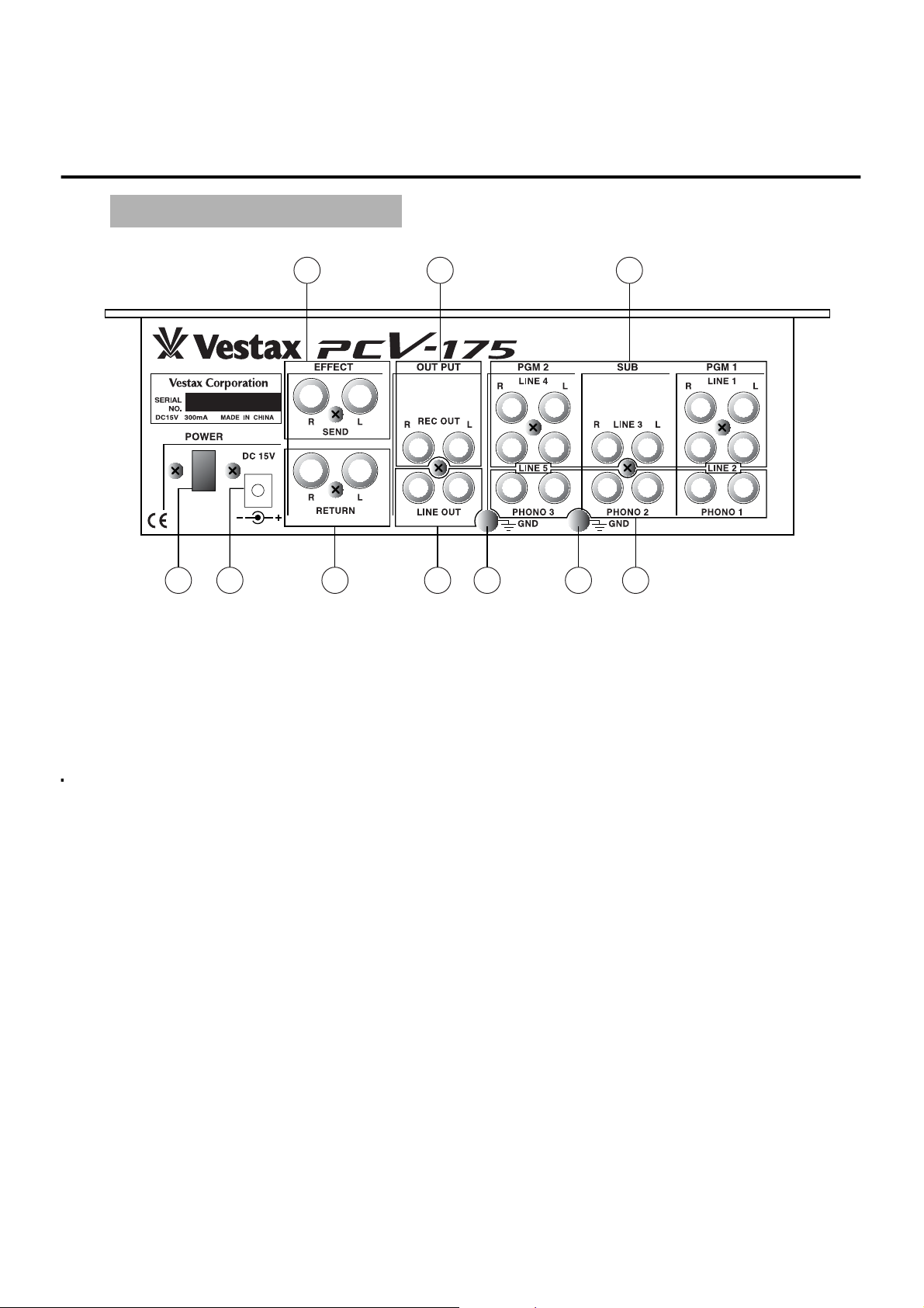
8
REAR PANEL SECTION
○26POWER SWITCH
○
27
LINE OUTPUT JACK
Connect to the power amplifier.
○28REC OUT JACK (RCA PIN JACK)
Connect to the input jack of the tape recorder, MD,
DAT, etc. The output level of this jack is fixed and
does not change with the master volume level
volume.
○29PHONO INPUT JACK
Input jack for the turntable with MM (Moving
Magnet) type cartridge.
○30GROUND TERMINAL
Connect this terminal to the ground lead of the
turntable.
○31LINE INPUT JACK
Input jack for the line level equipment such as CD
PLAYER, TAPE DECK, DAT, MD, etc.
○32EFFECT SEND JACK
Connect to the input of the external effects.
(Delay,Reverb etc)
○33EFFECT RETURN JACK
Connect to the output of the external effects.
○34AC POWER JACK
Connect the external power supply (DC-15A).
Connecting wrong power supply may cause severe
damage to the unit.
32
33
28 31
27 30 30 2926 34
Page 10
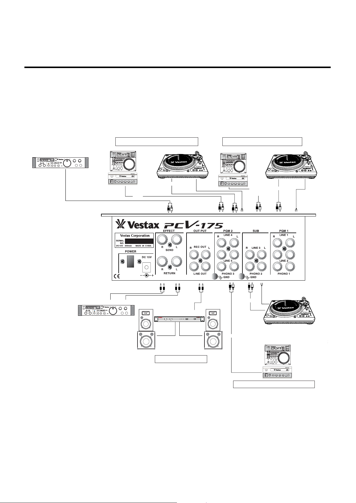
9
CONNECTIONS
CHANNELACHANNEL
B
MAX MINI MAX MINI
PROTECT B.T.L POWER
POWER
INPUT
PEAK
INPUT ON / OFF
PEAK
PLAY/PAUSE
CUE
PLAY/PAUSE
CUE
KEYPITCH
REVERSE
OPEN/
CLOSE
STOP
DISPLAY
REPEAT
AB
SEARCH
TRACK
MIN SEC FRM
LOCATE
ENTER 1 2 3
LOOP
START
END
RELOOP/EXIT
POINT FOCUS
MONITOR
PLAY/PAUSE
CUE
PLAY/PAUSE
CUE
KEYPITCH
REVERSE
OPEN/
CLOSE
STOP
DISPLAY
REPEAT
AB
SEARCH
TRACK
MIN SEC FRM
LOCATE
ENTER 1 2 3
LOOP
START
END
RELOOP/EXIT
POINT FOCUS
MONITOR
CDPLAYER[VESTAX CDX-3
CDPLAYER[VESTAX CDX-35]
CDPLAYER[VESTAX CDX-35]
MAIN SPEAKER MAIN SPEAKER
TAPE RECORDER, CD, MD, DAT, etc.
TURNTABLE[VESTAX
REC OUT
LINE1
or
LINE2
LINE4
or
LINE5
PHONO3
LINE3
PHONO1
PHONO3
GROUND
LEAD
EFFECTOR ( DELAY, REVERB, SAMPLER )
POWER AMPLIFIER[VESTAX PT-X1000A]
BROUND LEAD
GROUND
EFFECT
SEND
EFFECT
RETURN
IN OUT
LINE
OUT
GND
GNDGND
OUT PUT
CD, MD, Player, TAP
CD, MD player, TAPE DECK, etcCD, MD player, TAPE
TURNTABLE[VESTAX TURNTABLE[VESTAX PDX-2000]
Page 11
10
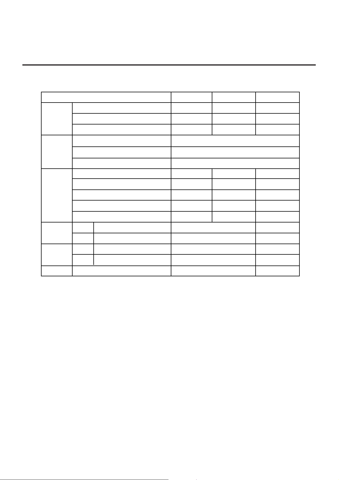
SPECIFICATIONS
INPUT
SECTION
EQUALIZER
SECTION
MIC(1/4 PHONE JACK) -50dBv -20dBv 3.3kΩ
PHONO 1〜3L/R (RCA JACK) -42dBv -22dB v 470kΩ
LINE 1〜5L/R (RCA JACK) -10dBv +14dBv 47kΩ
HI 10KHz +6dB 〜-24dB
MID 1KHz +6dB 〜-24dB
LOW 80KHz +6dB 〜-24dB
RATED OUTPUT
MAXIMUM OUTPUT
INPEDANCE
LINE L/R
( RCA JACK )
-4dBv +10dBv 10kΩ OVER
REC OUT L/R
( RCA JACK )
-10dBv +10dBv 10kΩ OVER
EFFECT SEND
(1/4' PHONE JACK )
-10dBv +14dBv 10kΩ OVER
HEAD PHONE(1/4' PHONE JACK ) 130mW 8Ω OVER/47Ω
MIC 30Hz 〜 20kHz ±3dB CROSSFADER CROSSTALK > 75dB
LINE 20Hz 〜 20kHz ±1dB CHANNEL CROSSTALK > 65dB
MIC >60dB POWER SUPPLY
DC15V ADAPTOR
LINE >85dB DIMENSIONS(W×H×D) 270×89×353
WEIGHT 4kg
OUTPUT
SECTION
FREQUENCY
RESPONSE
S/N RATIO
NOMINAL INPUT
LEVEL
MAXIMUM INPUT
LEVEL
INPEDANCE
Page 12

Vestax Corporation
MAY.2001 PCV175 E2
Page 13
 Loading...