

Vestamatic VRS SMT 01580011, VRS SMT 01580010 Installation And Operating Instructions Manual
VRS SMT Light Receiver
VRS FMT Light Receiver
Art. no.:
01580010 / 01580011
VRS SMT Light Receiver Art. no.: 01580010
VRS FMT Light Receiver Art. no.: 01580011
VRS radio receiver to connect a light source
in SMT or FMT Housing.
Installation and Operating Instructions
Short description
Radio receiver for control a light source
Operation via all hand and wall transmitters of the Vestamatic Radio
System (VRS)
Safety precautions
– Contact a professional electrician to install the control sys-
tem, because the control system requires a power supply of
230VAC, 50 Hz.
– Check the control system for signs of mechanical damage
after unpacking. If you notice any shipping damage, do not
start up the control system and notify your supplier immediately.
– The control system should only be used for the purpose speci–
fied by the manufacturer (refer to the operating instructions).
Any changes or modifications thereof are not permissible and
will result in loss of all warranty claims.
– If the control units or the connected sunshade cannot be oper-
ated without presenting a hazard, it must be switched off and
prevented from being switched on unintentionally.
Table of loads
Type of load Max. load
Resistive load:
Light bulbs 230VAC,
Halogen lamps etc.
Inductive load:
Halogen lamps with wound transformers
Fluorescent lamps (series)
Fluorescent lamps (parallel)
Capacity EB:
Electronic ballasts,
electronic transformers etc.
10 A / 2300 VA
2.6 A / 600 VA
10 A / 2300 VA
2.6 A / 600 VA
4 A / 920 VA
Functional description
The radio receiver is used for switching mains powered devices in the
operating modes ON / OFF and Timer.
The receiver can be operated by hand and wall transmitter of Vestamatic
radio system (VRS).
Assembly and installation
WARNING!
Improper installation and commissioning may lead to per-
Risk of injury due to improper installation and commissioning.
sonal injury or property damage.
Therefore:
– When connecting the device, observe the currently valid VDE
standards (in particular DIN VDE 0100/0700), your local power
company’s regulations and the current accident prevention
regulations.
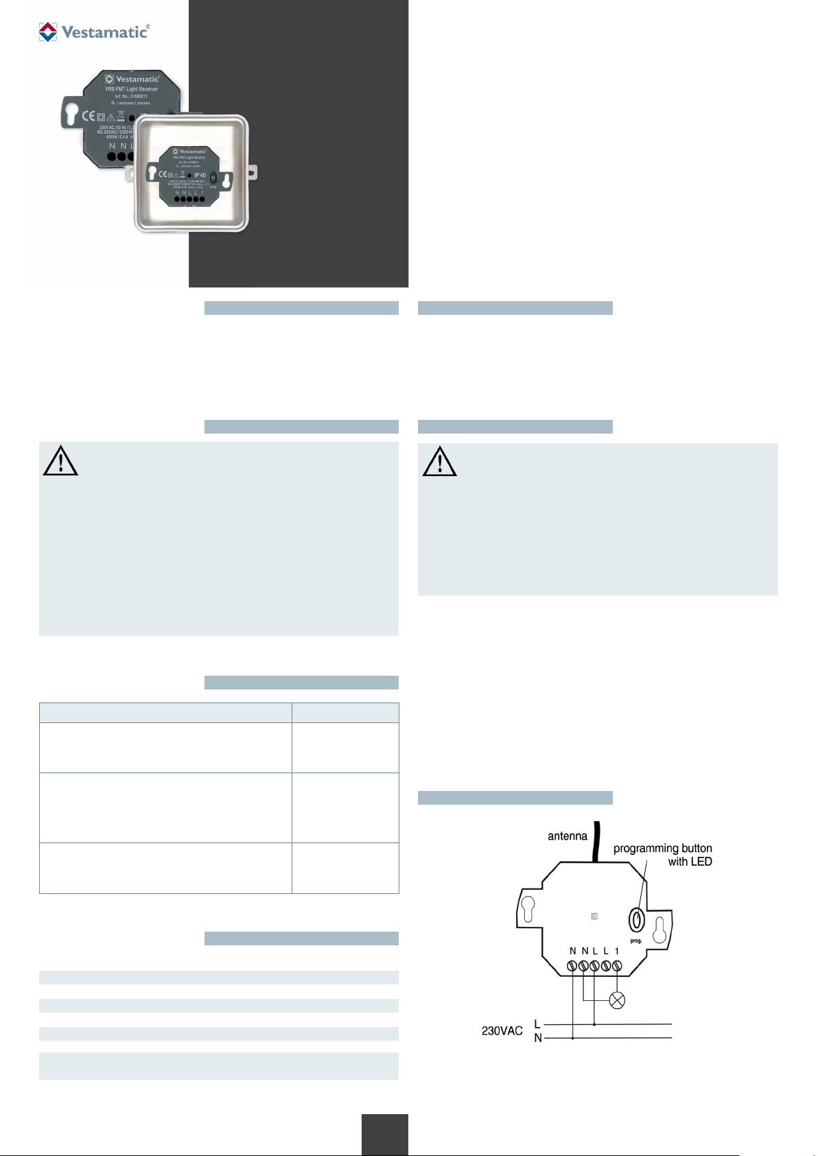
– Connect the control in accordance with the wiring diagram.
Notes for professional electricians
1. Switch off the control power supply.
2. Connect the cables in accordance with the wiring diagram.
3. Mount the receiver on a suitable mounting location
(see chapter “Instructions for radio receiver”).
4. Switch on the power supply.
5.
After connecting the receiver is in operation mode. The LED is off.
6.
Transfer the codes of the transmitters to the receiver
(see section “programming a radio transmitter”).
Wiring diagram
Technical data
Power supply: 230VAC, 50 Hz
Power consumption: 35 mA
Radio frequency: 868 MHz
Protection degree: IP 40 (FMT); IP 54 (SMT)
IP class: II
Operating temperature: -20 °C (-4 °F) to +60 °C (140 °F)
Dimensions (L × W × H): 46 × 46 × 25 mm
Conformity:
p
1/2
G
Art.-Nr.: 85601421 F1 • Vestamatic GmbH • Dohrweg 27 • D-41066 Mönchengladbach • www.vestamatic.com
Subject to modifications.© Vestamatic GmbH
VRS SMT/FMT Light Receiver
Programming + Operating modes
For Programming (see “Programming a radio transmitter” there are 3 programming modes for the 3 operating modes of the receiver, they are displayed by different LED flashing patterns.
Programming
mode
1 ON / OFF
2 ON / OFF
3 Timer mode
You can change from the operating mode to the programming mode 1 and
from one programming mode to the next by briefly
the programming button:
Operating mode
programming mode 3 p operating mode. etc.
In the delete mode you can delete specific transmission codes memorized
by the receiver.
1. Keep the programming button pressed for more than 1.6 seconds. The
delete mode is activated. The LED flashes rapidly.
2. Press the selected transmitter channel button. As soon as the code has
been deleted, the LED lights up for 4 seconds and then flashes again
rapidly.
3. Repeat step 2 with another transmitter or briefly (< 1.6 seconds) press
the programming button in order to return to the operating mode.
Operating mode LED signal
(flashes)
(2 button operation)
(1 button operation
> 1.6 seconds: OFF)
7 minutes, retrigger
(1 button operation)
(< 1.6 seconds) pressing
p programming mode 1 p programming mode 2 p
Deleting specific transmission codes
Programming a radio transmitter
In this mode you can transfer the codes of your transmitters to the receiver
NOTE!
Generally you only have to transfer the code of one button
per transmitter channel. The code of the other transmitter
buttons will be assigned automatically.
1. Briefly (<1.6 sec.) press the programming button. Programming mode 1
is activated and the LED flashes (see table).
2.
Press and hold a transmitter channel button. When radio receiver added
the transmitter, the LED lights up for 4 seconds and then flashes again.
Release the transmitter button.
3. Repeat step 2 with the other transmitters. Optionally, you can store up to
32 transmitters in each mode of the radio receiver. It is also possible to
change to the next programming mode.
4.
Briefly (<1.6 sec.) press the programming button to return to the operating
mode.
NOTE:
In case of a longer power failure programming of the receiver
remains.
Reset (Deleting all transmitter)
In the reset mode you can delete all codes memorized by the receiver.
1. Keep the programming button pressed for more than 1.6 seconds. The
delete mode is activated. The LED flashes rapidly.
2. Press the programming button again and keep it pressed for more than
1.6 seconds. If the memory has been deleted completely, the LED lights
up for 4 seconds and then flashes again rapidly.
3. Briefly (< 1.6 seconds) press the programming button to return to the
operating mode.
to
.
Instructions for radio receiver
ATTENTION!
Radio transmission is not suitable for safety operations,
such as emergency-stop, emergency call or warning signals.
Signals are transmitted across the Europe-wide approved 868 MHz frequency band. The radio transmission range largely depends on the constructional circumstances of the building. If other adjacent radio devices are
simultaneously sending signals, mutual interferences cannot be debared.
Such interferences can also affect individual units of a group of receivers.
Observing the following instructions will minimize these interferences:
Avoid to mount radio receivers onto or adjacent to metal surfaces.
Maintain minimum 50 cm clearance to consumer loads, such as micro-
wave ovens or TV sets.
Keep a minimum clearance of 50 cm between each mounted radio re-
ceiver.
Keep a minimum clearance of 50 cm between a radio receiver and a
radio transmitter.
If a radio-transmitted command cannot be clearly detected, the command
execution will be suppressed by means of an integrated automatic safety
function. The command must then be issued again.
Disposal of waste
The disposal of electrical equipment and batteries in household waste
is strictly forbidden.
The symbol (dustbin crossed out, in line with WEEE Appendix IV) in-
dicates separate collection of electrical and electronic products in EU
countries. Do not dispose of the device or battery in your household
waste. Ask your town or local council about the return and collection
systems available in your area to dispose of this product.
2/2
G
Art.-Nr.: 85601421 F1 • Vestamatic GmbH • Dohrweg 27 • D-41066 Mönchengladbach • www.vestamatic.com
Subject to modifications.© Vestamatic GmbH
 Loading...