

Vestamatic VL-MM-230-35 Series, VL-MM-230-35/6Nm, VL-MM-230-35Q/6Nm, VL-MM-230-35/10Nm, VL-MM-230-35S/10Nm Installation And Operating Instructions Manual
G
PRO · VL-MM-230-35
PRO
8050 002 GB 4717 A10
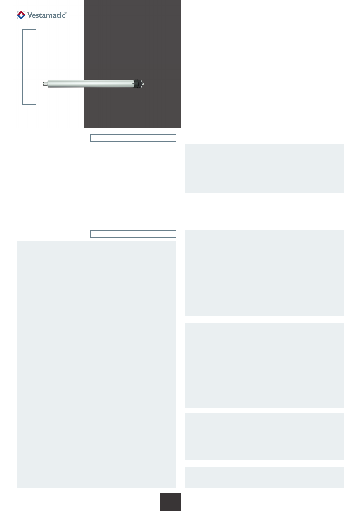
VL-MM-230-35
M-Line motors
1. Safety precautions (safety measures)
2. Short description (identification of products)
3. Scope of delivery
4. Intended use
5. Technical data
6. Installation, Assembly, Disassembly
7. Troubleshooting
8. Warranty
9. Maintenance
10. Disposal of waste
11. Service / Contact
Vestaline
CONTENTS
VL-MM -230-35 /6Nm
Art.-no.: 01066000
VL-MM -230-35Q/6Nm Art.-no.: 01066005
VL-MM -230-35/10Nm Art.-no.: 01066011
VL-MM -230-35S/10Nm Art.-no.: 01066031
Vestaline motors for controlling roller shutters, blinds and screens.
Installation and Operating Instructions
– Before the motor is installed, all un needed wires must be
removed and all devices which are not required for actua tion
with a power drive must be put out of operation.
– The actuating element of a hand release has to be installed
at a height of less than 1.8 m.
– The mains cable of this device cannot be replaced. If the
mains cable is damaged, the device has to be discarded.
Ä
1. Safety precautions
WARNING!
Important safety information.
Follow these instructions to ensure the safety of persons.
The instructions must be stored.
– Contact a professional electrician to install the motor, be cause
the motor requires a power supply of 230VAC, 50 Hz.
– Check the motor for signs of mechanical damage after un-
packing. If you notice any shipping damage, do not start up
the motor and notify your supplier immediately.
– The motor should only be used for the purpose specified by
the manufacturer (refer to the operating instructions). Any
changes or modifications thereof are not permissible and will
result in loss of all warranty claims.
– Technical data can be found on the type label of the tubular
motor.
– If the motor cannot be operated without presenting a hazard,
it must be switched off and prevented from being switched
on unintentionally.
– When performing work on the windows, motor or connected
shades, protect them against unauthorised or unintentional
operation.
– Moving parts of the motor installed under 2.5 m above the
floor level should be protected.
– This motor is not intended for use by persons (including chil-
dren) with reduced physical, sensory or mental abilities or
lack of experience and / or lack of knowledge, unless they are
supervised by a person responsible for their safety, or received instructions on how the device is to be used.
– Children should be supervised to ensure that they do not
play with the device.
– Children are not allowed, to play with fixed controls. Keep
remotes away from children.
– The installation has to be checked frequently for imbalance
or of signs of wear, damaged cables or springs, if applicable.
– Automatically controlled systems have to be disconnected
from the supply network, e. g. if maintenance work has to be
done close to them.
ATTENTION!
Ä
Ä
Ä
Ä
Pay attention to the following European guidelines:
– The cables must conform to the applicable VDE standard.
– If installing motors with a PVC H05VV-F cable, the cable on
surface-mounted outdoor installations and recessed-mounted installations must be protected by a cable conduit or
cable duct.
– When installing the motor an all-pole disconnection with a
contact gap of at least 3 mm per pole must be provided.
– The up and down directions of the switch resp. button
must be electrically or mechanically locked against each
other. The change over time for changing the running direction (up / down) must be at least 0.5 sec.
WARNING!
Risk of injury due to improper installation and commissioning.
Improper installation and commissioning may lead to personal
injury or property damage.
Therefore:
– When connecting the device, observe the currently valid VDE
standards (in particular DIN VDE 0100/0700), your local power company’s regulations and the current accident prevention
regulations.
– Connect the motor in accordance with the wiring diagram.
– It is important for the safety of professional electricians to
follow the user instructions. Please keep instructions for re-
ference.
ATTENTION!
– Follow the safety instructions according to EN 60335-2-97.
– Additional components for the implementation of the installa-
tion, such as adaptors and brackets must be chosen among
those offered by the producer.
– When mounting the drive always use the safest and most
suitable tubular motor and mounting bracket.
IMPORTANT!
Any screws used to fix the system must in no way touch the
motor. Please refer to fig. 4.1 to 4.5.
Art.-Nr.: 8050 002 GB 4717 A10 • Vestamatic GmbH • Dohrweg 27 • D-41066 Mönchengladbach • www.vestamatic.com
1/4
G
Subject to modifications.© Vestamatic GmbH
PRO ∙ VL-MM-230-35
2. Short description
Motor 35 mm tube diameter
Mechanical setting of limit positions via screws on the motor head
2.5 m connection cable
3. Scope of delivery
Motor 35 mm tube diameter with 2.5 m connection cable
Operating instructions
Regulator
4. Intended use
These types of tubular motor described in this manual is intended solely for
controlling roller shutters, blinds or screens. These types of tubular motor
cannot be use in potentially explosive area.
These types of tubular motor are designed for using in a single sunshade
system.
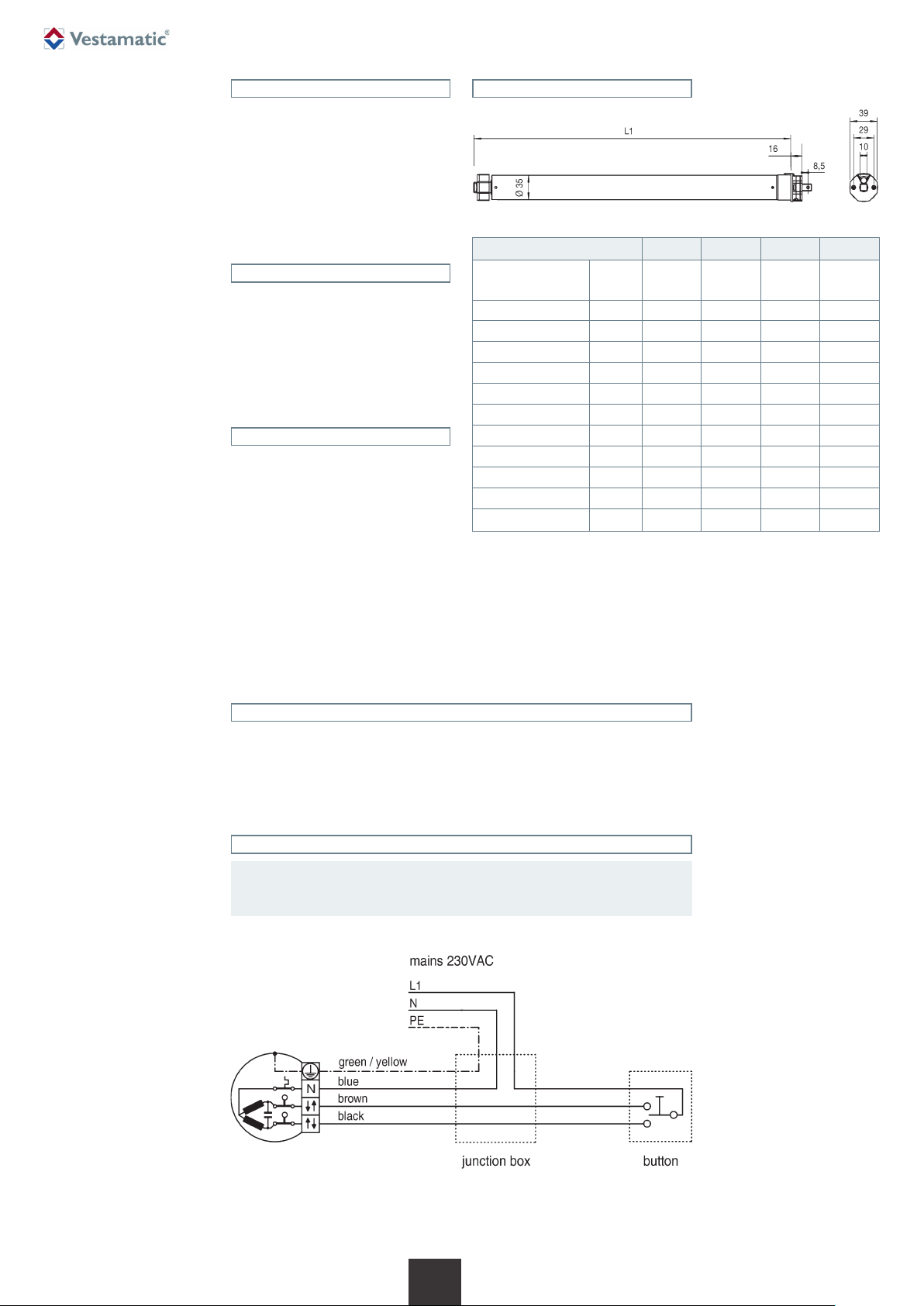
5. Technical data
Article VL-MM-230-35/ 6Nm Q / 6Nm 10Nm S / 10Nm
Art.-no.:
Torque (nominal) Nm 6 6 10 10
Rated speed rpm 28 28 17 17
Tractive power kg 17 17 25 25
Supply voltage VAC 230 230 230 230
Frequency Hz 50 50 50 50
Rated power W 154 154 154 154
Rated current A 0.67 0.67 0.67 0.67
Running time Min. 4 4 4 4
Protection degree IP 44 44 44 44
Max. limit turns turn 30 30 30 17
Length L1 mm 459 500 459 377
01066000 01066005 01066011 01066031
6. Installation, assembly, disassembly
Wire colours of motor connection cables:
– green/yellow: ground conductor/PE – brown: phase turning direction 1
– blue: neutral conductor/N – black: phase turning direction 2
6.1 Wiring diagram
ATTENTION!
Parallel control of more than one conventional drive motor can only be
Ä
implemented by means of isolating relays.
2/4
G
Art.-Nr.: 8050 002 GB 4717 A10 • Vestamatic GmbH • Dohrweg 27 • D-41066 Mönchengladbach • www.vestamatic.com
Subject to modifications.© Vestamatic GmbH

6.2 Assembly
1. The connection cable should be installed in an conduit to the junction
box, in compliance with the local building and electrical regulations.
Avoid any contact between moving objects and connection cables by
routing the cables according to figure 1.
2. Place the mounting bracket to the desired position. Assembly of the
motor can be performed on both sides.
3. Slide the crown (A) on the raceway (B). Be aware of the correct installation of the notch with the Adapter (D), (figure 2).
4. Place the tube adapter (E) on to the motor axle (F) and secure it with the
safety clip (G) that comes within the mounting-kit.
5. Be careful when sliding the tubular motor completely into the tubular
shaft, until the crown is covered into the tubular shaft, (figure 3). Under
no circumstances external force should be applied to the motor in any
way.
6. Place the motor head and tubular shaft into the mounting bracket and
check for proper fit. Secure the square pin of the motor head with the
safety cotter that comes with the mounting-kit. Make sure to install the
motor in a position that the adjustment screws are accessible from the
outside.
PRO · VL-MM-230-35
Fig. 1
Fig. 2
Fig. 3
Fig. 4.1 Fig. 4.2 Fig. 4.3 Fig. 4.4 Abb. 4.5
3/4
G
Art.-Nr.: 8050 002 GB 4717 A10 • Vestamatic GmbH • Dohrweg 27 • D-41066 Mönchengladbach • www.vestamatic.com
Subject to modifications.© Vestamatic GmbH

6.3 Setting the limit position switch
The limit position switch is pre-set to about two turns of the shaft.
Turning the adjusting screw towards the “+” increases the travel.
Turning the adjusting screw towards the“-” decreases the travel.
Refer to the diagrams opposite to see which adjusting screw should be
used for which switch-off point.
Setting the “lower” limit position
1. Move the motor downwards until the automatic limit position switch
independently stops the motor.
2. If the pre-set limit point cannot be reached, move the motor upwards
and then turn the relevant adjusting screw towards the “-” to shorten
the travel. If necessary, repeat this process until the motor stops at the
desired end position.
3. Now turn the adjusting screw towards the “+” until the motor has
reached the desired lower position.
PRO ∙ VL-MM-230-35
Setting the “upper
1. Move the motor upwards until the automatic limit position switch independently stops the motor.
2. If the pre-set limit point cannot be reached (e. g. material runs into the
cassette), move the motor downwards and then turn the relevant adjusting screw towards the “-” to shorten the travel. If necessary, repeat this
process until the motor stops at the desired end position.
3. Now turn the adjusting screw towards the “+” until the motor has
reached the desired upper position.
Problem Possible cause Solution
Motor is not responding. 1. No mains voltage. 1. Check mains voltage.
Motor starts slowly or makes too
much noise.
Motor rotation direction is wrong. Motor connection cables are reversed. Disconnect the supply line from the power, and swap
Motor stops while moving up or
downwards.
” limit position
6.4 Dissasembly
The workflow is the same as in the section “6.2 “Assembly” but in reverse
order. The setup of limit positions can be skipped.
7. Troubleshooting
2. Connection error. 2. Check connections (see wiring diagram).
3. Cutoff by internal temperature fuse. 3. Allow the motor to cool down for 20 min.
1. Connection error. 1. Check connections.
2. Installation error or undersized motor selected. 2. Check installation and motor load.
the black and brown conductors of the motor cable at
the controller.
1. Preset endpoint reached. 1. Set the end limits again, according to the instructions.
2. Cutoff by internal temperature fuse. 2. Allow the motor to cool down for 20 min.
Motor stops while moving upwards. Obstacle detected. Remove obstacle and steer the system in downward
8. Warranty
Principally, the General Terms and Conditions of the manufacturer, Vestamatic GmbH apply. The terms and conditions are part of the sales documents and handed over to the operator upon delivery. Liability claims for
personal or material damages are excluded when they can be at tri buted to
one or more of the following causes:
– Unintended use of the product.
– Opening of the product by the customer.
– Improper installation, commissioning, or operation of the product.
– Non-compliance with the specifications.
– Non-observance of the safety provisions and instructions of the Oper-
ating Instructions.
– Operation of the product with improperly installed connections, defec-
tive safety devices or improperly installed safeguards.
– Modifications to the product.
The motor is maintenance-free.
The disposal of electrical equipment and batteries in household
waste is strictly forbidden.
É
Vestamatic GmbH
Dohrweg 27
41066 Mönchengladbach / Germany
info@vestamatic.com
Phone: +49 2161 / 29 408-0
4/4
direction.
9. Maintenance
10. Disposal of waste
The symbol (dustbin crossed out, in line with WEEE Appendix IV)
indicates separate collection of electrical and electronic products in
EU countries. Do not dispose of the device or battery in your household waste. Ask your town or local council about the return and collection systems available in your area to dispose of this product.
11. Support / Contact
Subject to modifications.© Vestamatic GmbH
G
Art.-Nr.: 8050 002 GB 4717 A10 • Vestamatic GmbH • Dohrweg 27 • D-41066 Mönchengladbach • www.vestamatic.com
 Loading...