

Vestamatic MC P4 LoVo, MC P4 LoVo VRS Installation And Operating Instructions Manual
G
MC P4 LoVo / VRS
MC P4 LoVo
MC P4 LoVo VRS
Art.-no.:
01077420 / 01077417
Microprocessor-powered motor controller for four sunshade controls
Standard 3-wire central input
Direct connection available for four Lovoline SMI / ME motors or 24VDC motors
Connection available for group button
Connection available for four individual buttons
Separate connection terminals for mains supply and central transmission
10 different operating modes can be set, incl. inching mode and intelligent
decentralised operation
Motor run time/tilting time can be individually set
Control via VRS radio remote control or VRS wall-mounted radio transmitter
(MC P4 LoVo VRS)
MC P4 LoVo
Art.-no.: 01077420
MC P4 LoVo VRS Art.-no.: 01077417
Programmable motor controls for operating 4 sunshade devices
with group and individual controls, either wire-bound or
via 868 MHz radio link.
Installation and Operating Instructions
Technical dataShort description
Power supply:
Radio frequency (MC P4 LoVo VRS): 868 MHz
Fuse: T 4A
Output: 24VDC
Align switching time extend: 3 – 180 s
Align switching time retract: 180 s
Total permissible motor current: max. 2A
Operating temperature: 0 °C (32 °F) to +40 °C (104 °F)
IP class: IP 54
Dimensions (L × W × H): 170 × 134 × 85 mm
Conformity:
22 – 28VDC
p
Accessories
Control for creating sub-groups (GC 3-)
Safety precautions
– Contact a professional electrician to install the control system.
– Check the control system for signs of mechanical damage after un-
Ä
– The control system should only be used for the purpose specified by
– If the control unit cannot be operated without presenting a hazard, it must
– When performing work on the windows, controls or connected shades,
Ä
– When connecting the device, observe the currently valid VDE standards
– Connect the control in accordance with the wiring diagram.
– Only use central control with floating contact output.
packing. If you notice any shipping damage, do not start up the control
system and notify your supplier immediately.
the manufacturer (refer to the operating instructions). Any changes or
modifications thereof are not permissible and will result in loss of all
warranty claims.
be switched off and prevented from being switched on unintentionally.
protect them against unauthorised or unintentional operation.
Assembly and installation
WARNING!
Risk of injury due to improper installation and commissioning.
Improper installation and commissioning may lead to personal injury or
property damage.
Therefore:
(in particular DIN VDE 0100/0700), your local power company’s regulations and the current accident prevention regulations.
Conformity
The product meets the essential requirements of R & TTE Directive 1999 / 5 / EC. The
declaration of conformity is available on the following website: www.vestamatic.com
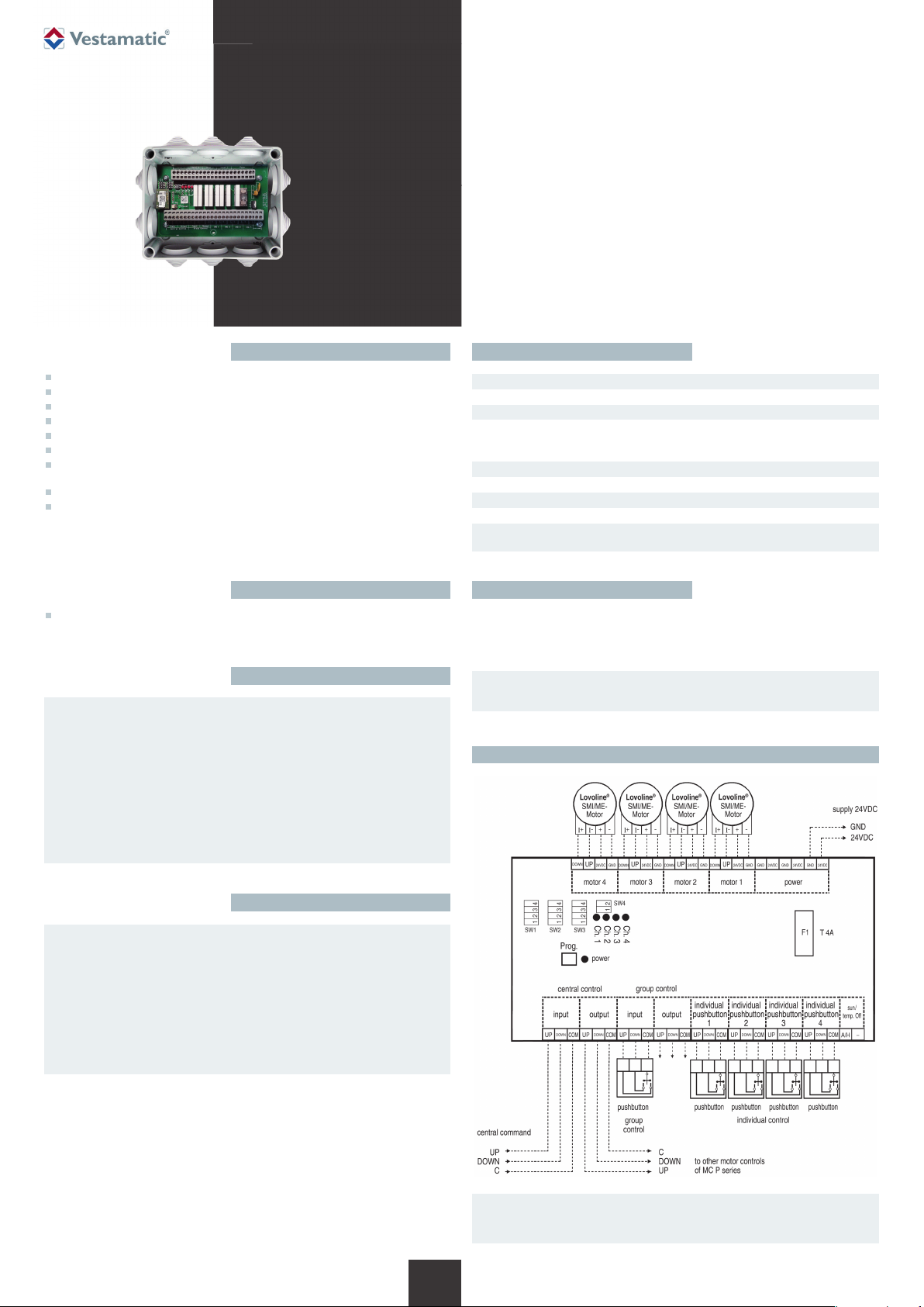
ATTENTION! (Notice applies for all displayed wiring diagrams)
Only use central control with floating contact output.
Ä
Wiring diagram – for connecting Lovoline SMI/ME motors
Notes for professional electricians
1. Switch off the power supply.
2. Undo the housing cover screws and lift off the housing cover.
3. Use the four mounting holes at the edges of the housing to mount it.
4. Connect the power supply cables and external connections ac cord ing to the wiring
diagram. Do not lay cables above or below the PC board.
5. Set the desired operating mode.
6. Set the desired motor run time and the tilting time, if necessary.
7. Switch on the power supply.
8. Check the motor’s direction of rotation and correct it, if necessary.
9. Replace the housing cover and tighten the housing cover screws.
1/4
1/4
G
G
IMPORTANT!
When using Lovoline SMI / ME motors, DIP S4 is set as follows:
Ä
1 = ON; 2 = OFF.
Subject to modifications.© Vestamatic GmbH
Art.-Nr.: 8600 001 GB 4416 A00 • Vestamatic GmbH • Dohrweg 27 • D-41066 Mönchengladbach • www.vestamatic.com
MC P4 LoVo / VRS
Wiring diagram – for connecting 24VDC standard motors
Wiring diagram – for connecting 24VDC motors
Operation
WARNING!
Neither group operation nor individual operation is possible while a
Ä
central command is being executed.
Individual or group operation is performed by using a locked/unlocked button.
The following descriptions are valid only for the radio version
MC P4 LoVo VRS.
i
Enter programming mode/Program VRS radio transmitter
Press the Prog. button until the red “Ch.1” LED flashes.
You can now program a radio transmitter for motor 1. Programming mode will now
remain open for 2 minutes. To select other channels, proceed as follows.
When the red “Ch.1” LED flashes
Briefly press the Prog. button, the red “Ch. 2” LED flashes = transmitter for motor 2
can be programmed.
Briefly press the Prog. button, the red “Ch. 3” LED flashes = transmitter for motor 3
can be programmed.
Briefly press the Prog. button, the red “Ch. 4” LED flashes = transmitter for motor 4
can be programmed.
Briefly press the Prog. button, the red “Ch.1+2” LED flashes = transmitter for
motor 1 + 2 can be programmed.
Briefly press the Prog. button, the red “Ch.3+4” LED flashes = transmitter for
motor 3+4 can be programmed.
Briefly press the Prog. button, the red “Ch.1-4” LED flashes = transmitter for
-
4 can be programmed.
motor 1
:
Functions, programming and cancelling the remote control settings
A. LED indication of selected channel of the transmitter.
To change channel:
Press and hold “stop” for 3–6 s (LED start to blink),
then use the ON/ UP Q or OFF/DOWN q button to
select wanted channel and confirm by pressing “stop”.
A.
Pair the transmitter to the control box
Select the required switching channel on your remote control. Change channel as
described above by pressing the STOP button.
Now open the MC P4 LoVo VRS programming mode.
Example: Program the radio remote control to “Ch. 1” = motor 1: Press the
MC P4 LoVo VRS Prog. button until the red “Ch.1” LED flashes. Now press the ON/
UP Q, OFF/DOWN q or STOP button on the radio remote control.
The 4 red LEDs on the MC P4 LoVo VRS will light up (for 1 second) to indicate that
programming was successful. Motor 1 channel can now be operated.
Briefly press the ON/ UP Q or OFF /DOWN q button = inching mode
Press the ON/ UP Q or OFF/DOWN q button for more than 3 seconds = self-locking
To program more channels/transmitter, proceed appropriately.
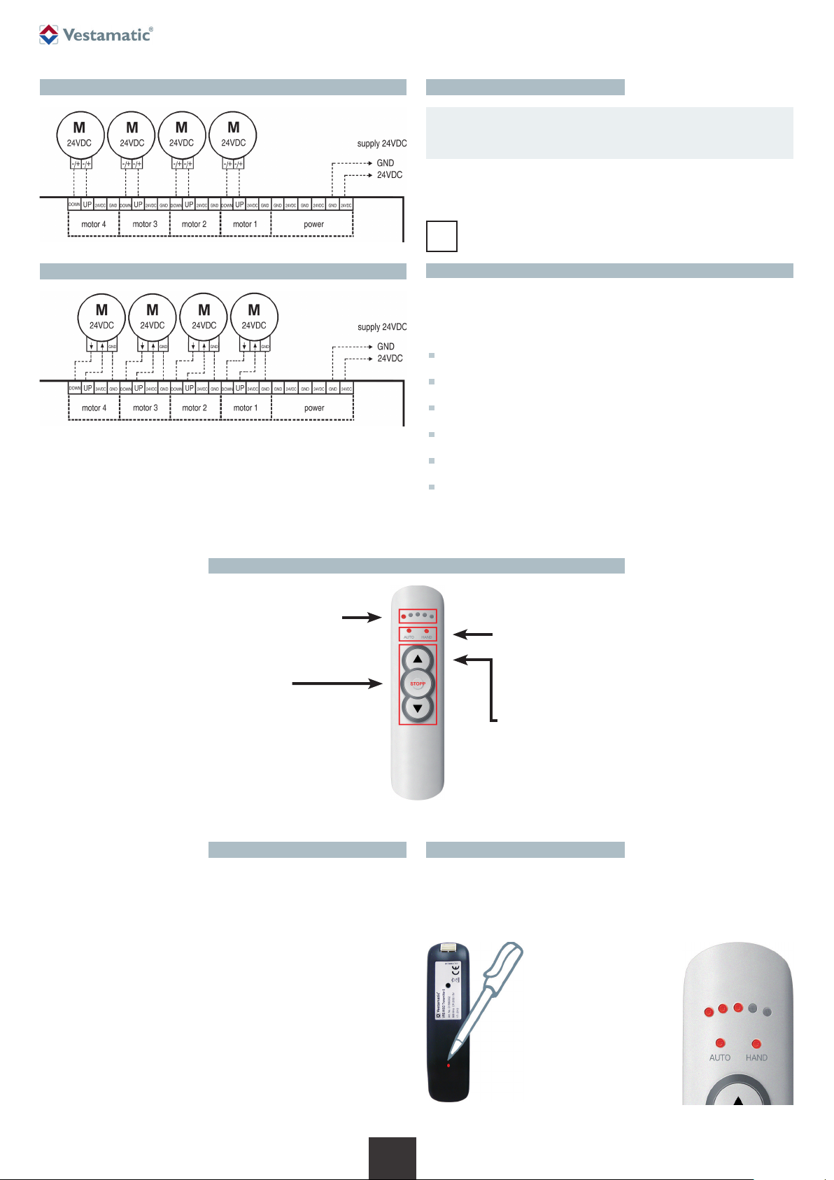
B. Radio remote control 5 K:
B.
C.
Normally used to select manual or automatic mode.
Not used for this device.
Radio remote control 10 K:
Left LED indication channel 1– 5
Right LED indication channel 6 –10
C. Manual control buttons.
Channel 1–10 = Motor / Shade
Button ON/ UP = Q
Button STOP
Button OFF/ DOWN = q
Cancelling the remote control settings
Select the switching channel on your radio remote control that you wish to cancel.
Change channel as described above by pressing the STOP button.
Now open the MC P4 LoVo VRS programming mode. Press the MC P4 LoVo VRS
Prog. button until the channel (red LED) that you wish to cancel flashes.
Now press the Prog. button
(Fig. A) on the back of the radio
remote control several times until
the following LEDs flash (Fig. B).
Then press the STOP button. The
4 red LEDs on the MC P4 LoVo
VRS will light up (for 1 second)
to indicate that the settings have
been cancelled.
2/4
2/4
G
G
Figure A Figure B
Subject to modifications.© Vestamatic GmbH
Art.-Nr.: 8600 001 GB 4416 A00 • Vestamatic GmbH • Dohrweg 27 • D-41066 Mönchengladbach • www.vestamatic.com
 Loading...