

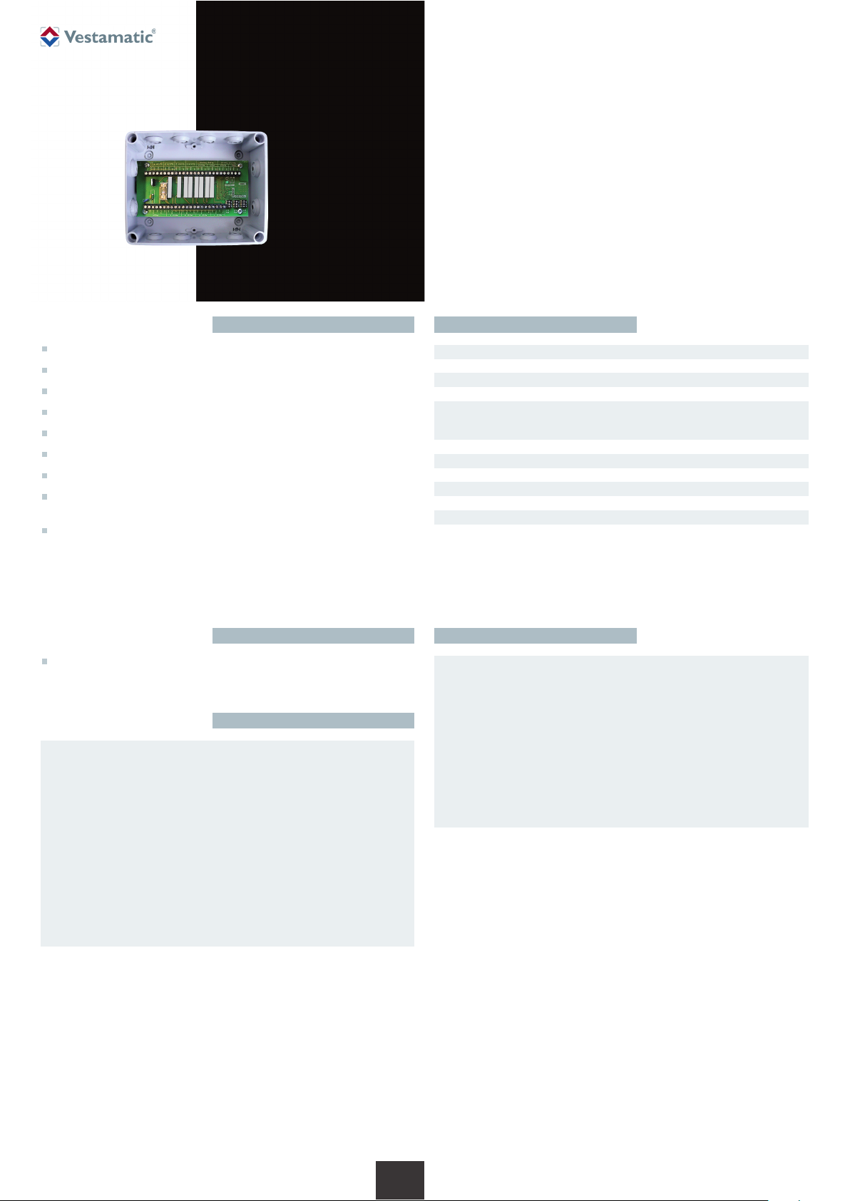
MC P4 LoVo
Art.-no.:
01077420
Installation and Operating Instructions
MC P4 LoVo Art.-no.: 01077420
Programmable motor control for operating
4 sunshade devices with group and individual control.
Technical dataShort description
Assembly and installation
Microprocessor-powered motor controller for four sunshade controls
Standard 3-wire central input
Direct connection available for four SMI LoVo motors or 24VDC motors
Connection available for group button
Connection available for four individual buttons
Separate connection terminals for mains supply and central transmission
Secure connection via screw-type terminal up to 2.5 mm²
10 different operating modes can be set, incl. inching mode and
intelligent decentralised operation
Motor run time/tilting time can be individually set
Notes for professional electricians
1. Switch off the power supply.
2. Undo the housing cover screws and lift off the housing cover.
3. Use the four mounting holes at the edges of the housing to mount it.
4. Connect the power supply cables and external connections according
to the wiring diagram. Do not lay cables above or below the PC board.
5. Set the desired operating mode.
6. Set the desired motor run time and the tilting time, if necessary.
7. Switch on the power supply.
8. Check the motor’s direction of rotation and correct it, if necessary.
9. Replace the housing cover and tighten the housing cover screws.
Safety precautions
– Contact a professional electrician to install the control system.
– Check the control system for signs of mechanical damage
after unpacking. If you notice any shipping damage, do not start
up the control system and notify your supplier immediately.
– The control system should only be used for the purpose
specified by the manufacturer (refer to the operating instructions). Any changes or modifications thereof are not permissible and will result in loss of all warranty claims.
– If the control unit cannot be operated without presenting a
hazard, it must be switched off and prevented from being
switched on unintentionally.
– When performing work on the windows, controls or connected
shades, protect them against unauthorised or unintentional
operation.
Ä
WARNING!
Risk of injury due to improper installation and commissioning.
Improper installation and commissioning may lead to personal
injury or property damage.
Therefore:
– When connecting the device, observe the currently valid VDE
standards (in particular DIN VDE 0100/0700), your local power
company’s regulations and the current accident prevention
regulations.
– Connect the control in accordance with the wiring diagram.
– Only use central control with floating contact output.
Ä
Art.-Nr.: 85201821 D1 • Vestamatic GmbH • Dohrweg 27 • D-41066 Mönchengladbach • www.vestamatic.com
Subject to modifications.
© Vestamatic GmbH
Power supply:
22 – 28VDC
Impulse voltage withstand level: 2.5 kV
Rated power: 2.6 W
Fuse: 4 AT
Software class: A
Total permissible motor current: max. 2A
Operating temperature: 0 ºC (32 °F) to +40 ºC (104 °F)
IP class: IP 54
Degree of contamination: 2
Mark of conformity: p
Dimensions (L × W × H): 170 × 144 × 88 mm
Output: 24VDC, 50 Hz
Align switching time extend: 3 – 180 s
Align switching time retract: 180 s
1/4
G
Accessories
Control for creating sub-groups (e.g. GC 6-, GC 3-)
The disposal of electrical equipment and batteries in household
waste is strictly forbidden.
The symbol (dustbin crossed out, in line with WEEE Appendix IV)
indicates separate collection of electrical and electronic products
in EU countries. Do not dispose of the device or battery in your
household waste. Ask your town or local council about the return
and collection systems available in your area to dispose of this
product.
É
MC P4 LoVo
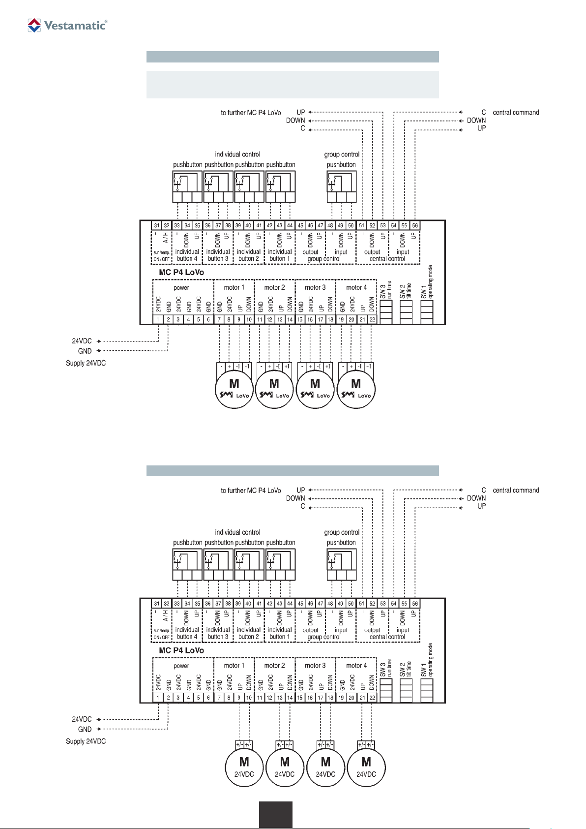
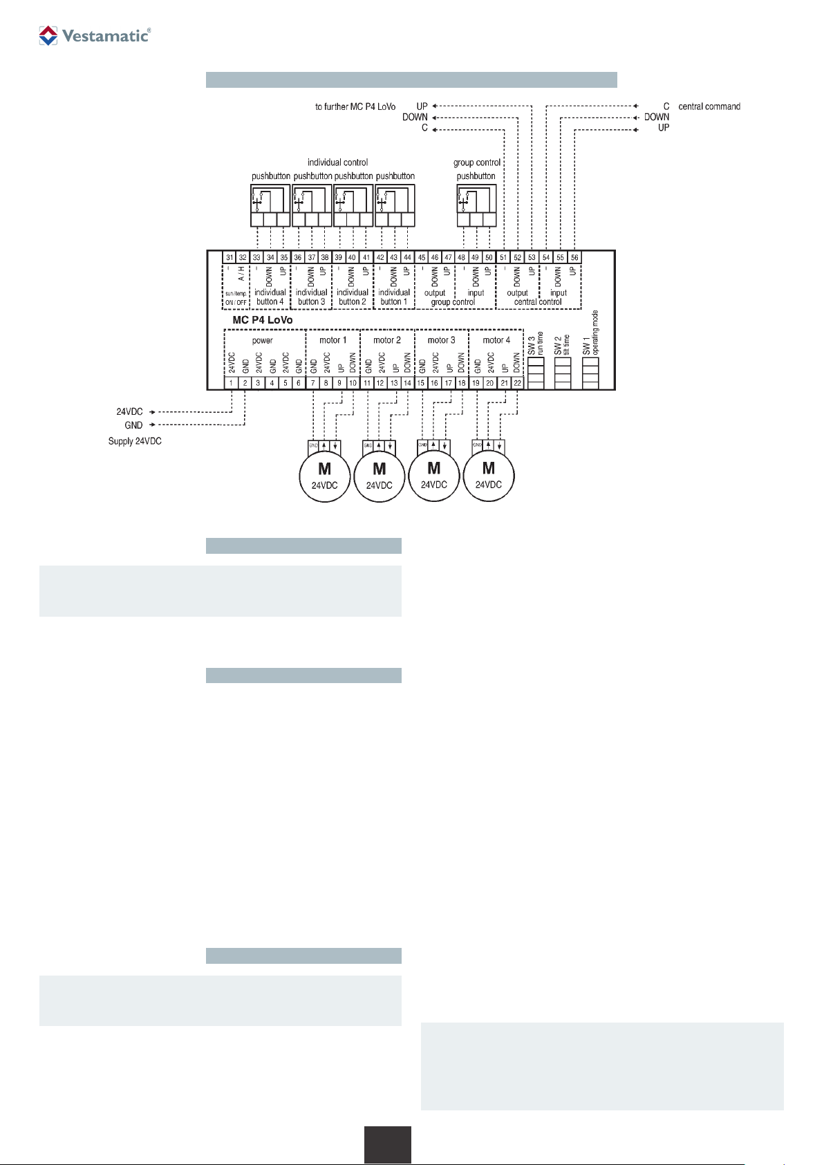
ATTENTION! (Notice applies for all displayed wiring diagrams)
Only use central control with floating contact output.
Ä
Art.-Nr.: 85201821 D1 • Vestamatic GmbH • Dohrweg 27 • D-41066 Mönchengladbach • www.vestamatic.com
Subject to modifications.
© Vestamatic GmbH
2/4
G
Wiring diagram – for connecting 24VDC SMI LoVo motors
Wiring diagram – for connecting 24VDC standard motors
IDS Function
The IDS (Intelligent Decentralised Sunshade control) feature enables the
sun- and temperature dependant control signals on the central controls to
be disabled when a button is pressed on the decentralised controls. No
additional installation work is required.
In operating mode 4 the IDS-Function enables you to suppress sun- and
temperature dependent extract or extend commands while all other central
commands, such as for privacy and safety protection use are continuously
executed.To enable this function connect a switch to terminal 31 and 32.
In operating modes 9 and 10, the sun- or temperature-dependent central
commands are masked by pressing the group or individual button.All further
sun- and temperature-dependent retract/extend commands will then be
masked for 4 hours. Each additional operation via the group command or
individual command will result in the sun- or temperature-dependent central
commands being masked for a further 4 hours. After the set period has
elapsed, the MC P4 LoVo control will be reset automatically and all sun- and
temperature-dependent central controls will then be executed as normal.
Functional description
Operating mode 2: The group/single command will be stored after 5s;
group/individual control of up to 5s will run the sunshade
for the duration of the command (dead man’s operation).
A central command will run the sunshade for the duration of the command (dead man’s operation).
Operating mode 3: The group/single command will be stored immediately.
A central command will run the sunshade for the duration of the command (dead man’s operation).
Operating mode 4: The group/single command will be stored after 2s;
group/individual control of up to 2s will run the sunshade
for the duration of the command (dead man’s operation).
Sun- and temperature dependent central commands
can be suppressed by means of a switch at the termi-
nals 31 and 32.
Operating mode 5: Special function 1
Operating mode 6: Special function 2
Operating mode 7: The group/single command will be stored immediately.
The central command will be stored immediately.
Operating mode 8: The group/single command will be stored after 2s;
group/individual control of up to 2s will run the sun-
shade for the duration of the command.
The central command will be stored after 2s; central
operation of up to 2s will run the sunshade for the
duration of the command.
Operating mode 9: The group/single command will be stored after 2s;
group/individual control of up to 2s will run the sunshade
for the duration of the command (dead man’s operation).
Sun- and temperature-dependent central commands
can be suppressed for 4 hours by pressing the group
or individual button.
Operating mode 10: The group/single command will be stored immediately.
Sun- and temperature-dependent central commands
can be suppressed for 4 hours by pressing the group
or individual button.
Operation
Individual or group operation is performed by using a locked/unlocked button.
MC P4 LoVo
Wiring diagram – for connecting 24VDC motors
WARNING!
Neither group operation nor individual operation is possible
while a central command is being executed.
Ä
WARNING!
The operating modes 4 to 6, 9 and 10 may only be used in
conjunction with Vestamatic controls with IDS functionality.
Ä
Art.-Nr.: 85201821 D1 • Vestamatic GmbH • Dohrweg 27 • D-41066 Mönchengladbach • www.vestamatic.com
Subject to modifications.
© Vestamatic GmbH
3/4
G
NOTE FOR OPERATING MODES 9 AND 10!
Pressing the group button will block all 4 outputs for sun- and
temperature-dependent central commands for 4 hours simultaneously. Pressing an individual button will only block that particular output from sun- and temperature-dependent central
commands for 4 hours.
I
Operating mode 1: The group/single command will be stored after 2s;
group/individual control of up to 2s will run the sunshade for the duration of the command (dead man’s
operation).
A central command will run the sunshade for the
duration of the command (dead man’s operation).

Operating modeRun time of the extend command
DIP switch SW1:
S1 S2 S3 S4 Operating mode Tilting *
No. Application
OFF OFF OFF OFF 1 standard
venetian blinds /
curtain blinds
OFF OFF OFF ON 2 venetian blinds /
curtain blinds
with slow start velocity
OFF OFF ON OFF 3 roller shutters
OFF OFF ON ON 4
IDS venetian bl./curtain bl.
adjustable,
with autom. interlock 0 – 2 s
OFF ON OFF OFF 5
IDS spec. venetian blinds/
adjustable,
curtain blinds 0 – 5 s
special function 1
OFF ON OFF ON 6
IDS spec. venetian blinds/
adjustable,
curtain blinds 0 – 2 s
special function 2
OFF ON ON OFF 7 roller shutters no tilting
possible
OFF ON ON ON 8 venetian blinds
without slow
start velocity
ON OFF OFF OFF 9 IDS venetian blinds / adjustable,
curtain blinds 0 – 2 s
4 h locking
ON OFF OFF ON 10 IDS venetian blinds/ adjustable,
curtain blinds 0 – 2 s
4 h locking
DIP switch SW3:
S1 S2 S3 S4 Run time *
OFF OFF OFF OFF 5 s
OFF OFF OFF ON 10 s
OFF OFF ON OFF 15 s
OFF OFF ON ON 18 s
OFF ON OFF OFF 21 s
OFF ON OFF ON 24 s
OFF ON ON OFF 27 s
OFF ON ON ON 30 s
ON OFF OFF OFF 35 s
ON OFF OFF ON 40 s
ON OFF ON OFF 50 s
ON OFF ON ON 60 s
ON ON OFF OFF 80 s
ON ON OFF ON 100 s
ON ON ON OFF 120 s
ON ON ON ON 180 s
* This is where you can note your project-specific
basic settings.
possible
only via
central
command
possible
only via
central
command
possible
only via
central
command
possible
only via
central
command
The duration of the retract command is always 180 s.
MC P4 LoVo
Art.-Nr.: 85201821 D1 • Vestamatic GmbH • Dohrweg 27 • D-41066 Mönchengladbach • www.vestamatic.com
Subject to modifications.
© Vestamatic GmbH
Tilting time
Depending on the operating mode selected one of the following tables shall apply for
setting the required tilting time. The tilting time will only be executed after a central
command!
Tilting time table for operating mode 5
Tilting time table f. operating mode 4, 6, 9, 10
DIP switch SW2:
S1 S2 S3 S4 Tilting time *
OFF OFF OFF OFF no tilting
OFF OFF OFF ON 0.1 s
OFF OFF ON OFF 0.2 s
OFF OFF ON ON 0.3 s
OFF ON OFF OFF 0.4 s
OFF ON OFF ON 0.5 s
OFF ON ON OFF 0.6 s
OFF ON ON ON 0.7 s
ON OFF OFF OFF 0.8 s
ON OFF OFF ON 0.9 s
ON OFF ON OFF 1.0 s
ON OFF ON ON 1.2 s
ON ON OFF OFF 1.4 s
ON ON OFF ON 1.6 s
ON ON ON OFF 1.8 s
ON ON ON ON 2.0 s
* This is where you can note your project-specific basic settings.
DIP switch SW2:
S1 S2 S3 S4 Tilting time *
OFF OFF OFF OFF no tilting
OFF OFF OFF ON 0.4 s
OFF OFF ON OFF 0.7 s
OFF OFF ON ON 1.0 s
OFF ON OFF OFF 1.3 s
OFF ON OFF ON 1.6 s
OFF ON ON OFF 1.9 s
OFF ON ON ON 2.2 s
ON OFF OFF OFF 2.5 s
ON OFF OFF ON 2.8 s
ON OFF ON OFF 3.1 s
ON OFF ON ON 3.4 s
ON ON OFF OFF 3.7 s
ON ON OFF ON 4.0 s
ON ON ON OFF 4.5 s
ON ON ON ON 5.0 s
4/4
G
 Loading...