

Vestamatic LL-ME-BAT/I-24/0, 6 Nm RB IO-AIR Installation And Operating Instructions Manual
G
PRO · LL-ME-BAT/I-24/0,6 Nm RB IO-AIR
PRO
1253 001 GB 2218 A05
1. Safety precautions (safety measures)
2. Short description (Identification of products)
3. Intended use
4. Technical data
5. Installation, assembly, dissasembly
6. Startup and usage
7. Settings in radio operation IO-AIR
8. Warranty
9. Declaration of conformity
10. Maintenance
11. Disposal of waste
12. Service / Contact
LL-ME-BAT/I-24/0,6 Nm
1. Safety precautions
WARNING!
Ä
Important safety information.
– Contact a professional electrician for installation.
– Check the motor for signs of mechanical damage after un-
packing. If you notice any shipping damage, do not start up
the motor and notify your supplier immediately.
– The motor should only be used for the purpose specified by
the manufacturer (refer to the operating instructions). Any
changes or modifications thereof are not permissible and will
result in loss of all warranty claims.
– If the motor or the connected sunshade cannot be operated
without presenting a hazard, it must be switched off.
– When performing work on the windows, motor or connected
shades, protect them against unauthorised or unintentional
operation.
– Technical data can be found on the type label of the motor.
WARNING!
Ä
Important safety information.
Follow these instructions to ensure the safety of persons.
The instructions must be stored.
– Children are not allowed, to play with fixed controls. Keep
remotes away from children.
– The installation has to be checked frequently for imbalance
or of signs of wear.
WARNING!
Ä
Important safety information.
Follow all installation instructions, as incorrect installation
can lead to serious injuries.
– The installer must adhere to the standards and regulations
of the installation country and inform the customer about the
use and maintenance.
– Stationary mounted control units have to be fixed in sight.
– The rated torque and the rated operating time must be in
compliance with the attributes of the driven parts.
RB IO-AIR
Lovoline
IO-AIR
CONTENTS
LL-ME-BAT/I-24/0,6 Nm RB IO-AIR
Lovoline battery-motor motor for controlling
roller blinds and screens.
Art.-no.: 01010204
Installation and Operating Instructions
2. Short description
Lovoline motor with integrated battery and radio-technology
For accurate control of roller blinds/screens
User-friendly operation via IO-AIR radio transmitter
Slow motor speed at start and stop
Parallel control via broadcast-command
Adjustable motor speed in different steps
Intermediate position storage
Obstacle detection / Brake functionality
3.
Intended use
The type of motor listed in this manual is a battery-powered motor, that is
specifically for precise control of sun protection systems.
The motor cannot be used in potentially explosive area. This type of motor
is designed for using in a single sunshade system.
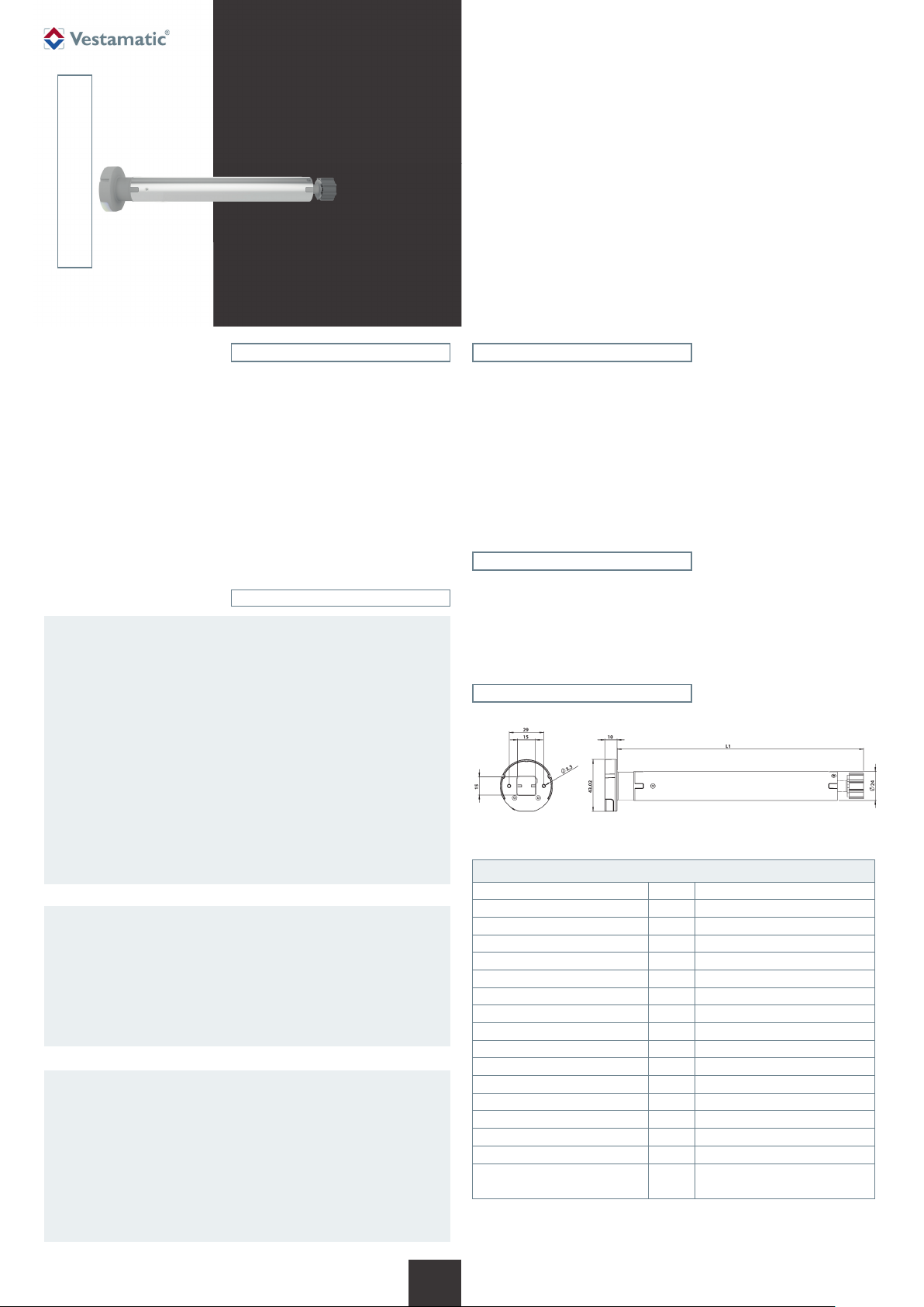
Technical data
4.
Article LL-ME-BAT/I-24/0,6 Nm RB IO-AIR
Art.-no.: 01010204
Power supply: DC 5V-USB
Battery-inside: Li-Ion battery 18
Output current (charger): A min. 1
Chargetime: hours up to 6
Rated power (nominal): W 3
Torque (nominal): Ncm
Draw weight: kg 1.3
Maximum on time: Min.
Output speed: rpm 15 – 50
Radio frequency: MHz 868
Radiated power: mW 12.5
Operating temperature: °C 0 °C (32 °F) to +60 °C (140 °F)
Protection degree: IP 20
LED: Colour: green / blue
Length L1: mm 259
Conformity:
1)
The battery can not be replaced.
2)
At a motor speed of 30 rpm.
2)
60
10 min. at +25 °C (77 °F) ambient temp.
p
1)
Art.-Nr.: 1253 001 GB 2218 A05 • Vestamatic GmbH • Dohrweg 27 • D-41066 Mönchengladbach • www.vestamatic.com
1/8
G
Subject to modifications.© Vestamatic GmbH
Ä
5. Installation, assembly, disassembly
ATTENTION!
Tubular motor might be switched off before reaching the
limit position:
Extraordinary large increases of load (anti-block-function) –
obstacles, sunshade system keeps jamming, tubular motor is
overloaded.
Remedy action:
– Removing the obstacle.
– Check the mechanical parts of the sunshade system.
– Use the correct tubular motor according the spezification of
the sunshade system.
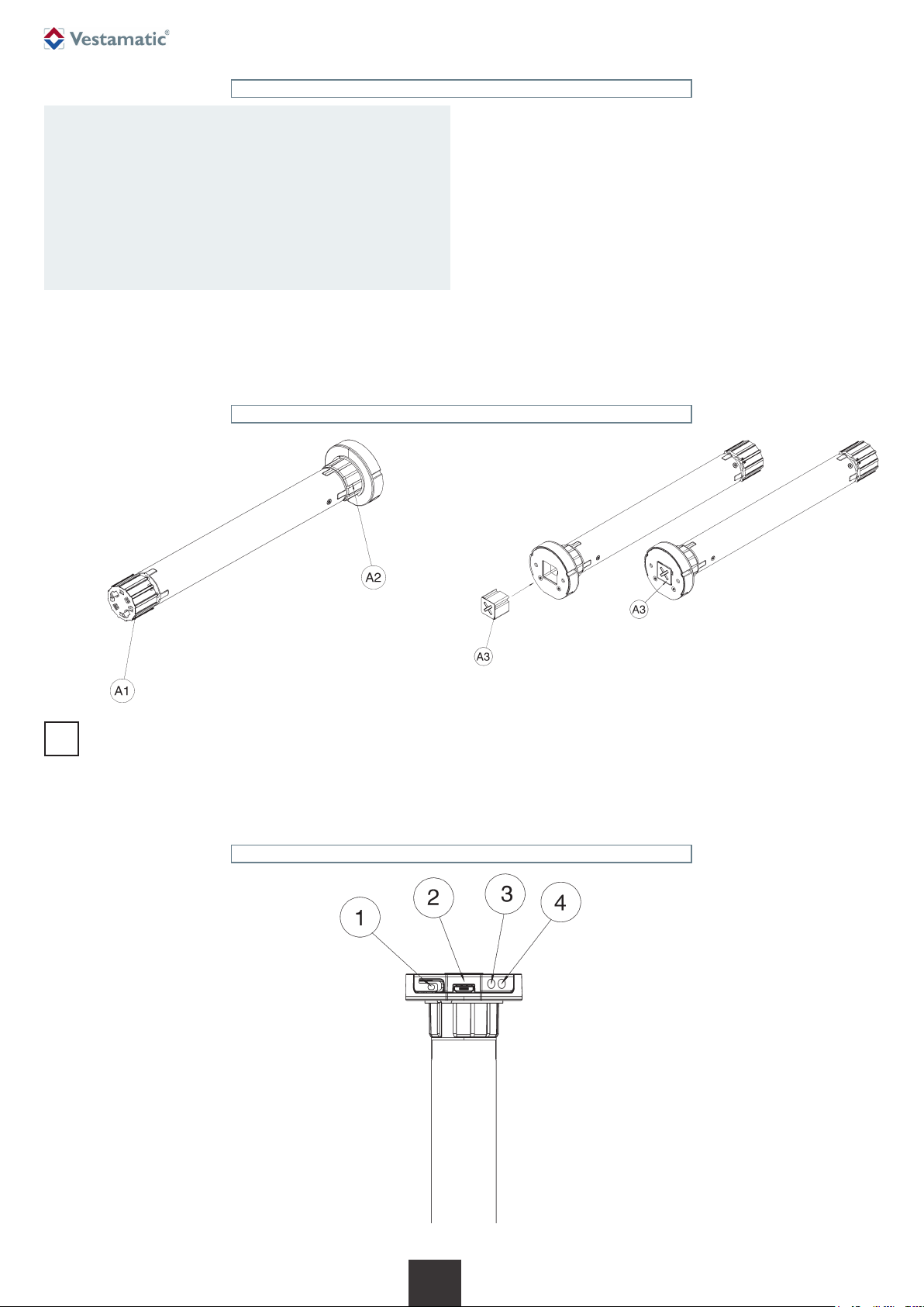
Assembly adapter sets
PRO ∙ LL-ME-BAT/I-24/0,6 Nm RB IO-AIR
The motor is designed for installation in various tubular shafts. The suitable
adapter sets can be found in the accessory program (not in cluded in the
scope of delivery).
A. Adapter sets (roller blinds/screens):
A1 = Drive
A2 = Crown
A3 = Bracket
To ensure proper installation, please observe the assembly description.
The motor has a terminal connection micro-USB. You will find suitable
connection cables in the accessory program (not included in the scope of
delivery).
NOTE:
When mounting the motor in the tubular system, make sure that the
i
PROG. button and the micro USB connector remain accessible.
5.1 Product description
Description:
1 PROG. button
2 Micro-USB connector
3 Blue LED
4 Green LED
2/8
G
Art.-Nr.: 1253 001 GB 2218 A05 • Vestamatic GmbH • Dohrweg 27 • D-41066 Mönchengladbach • www.vestamatic.com
Subject to modifications.© Vestamatic GmbH
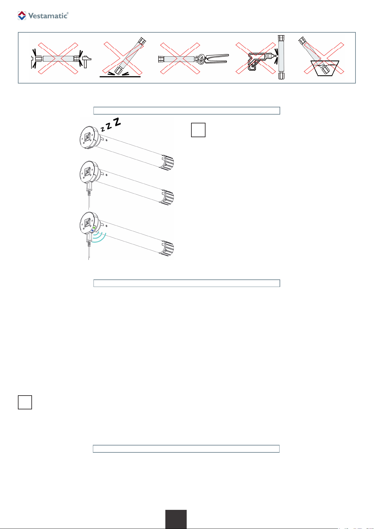
6. Startup and usage
NOTE:
Before first use, the motor should be fully charged.
i
1. The motor is in transport mode and must be woken up before first use.
2. To wake up the motor, connect a charger or a suitable power bank to
the Micro USB socket.
5V DC, min. 1 A
PRO · LL-ME-BAT/I-24/0,6 Nm RB IO-AIR
Charging the motor
To charge the motor, a standardized charger or a power bank with at least
1 ampere output current can be used.
Charging the motor is necessary if it shows one of the listed behaviors.
– Take a micro-USB charger or a power bank and plug the cable into the
micro-USB socket on the motor head.
– Plug the charger into the socket. A power bank may need to be activated.
– After approx. 1 sec the blue LED on the motor head is constantly lit. The
charging process is thus initiated. After about 1 minute the motor can
be moved again. The entire charging process can take up to 6 hours.
– Charging is completed when the blue LED on the motor head goes out
and the green LED lights up permanently. The micro-USB connector
can then be removed from the motor head.
NOTE:
When charging with a power bank, it will automatically switch off
i
after the charging process has ended, as a result the green LED
on the motor head will go out shortly after.
3. After plugging in the charger, the green and blue LEDs light up briefly.
The motor is now active.
Motor behavior with low battery
If the battery of the motor is running low, the motor will display the following
behaviors for ensuing movements.
Blue LED flashes
The blue LED on the motor head flashes twice every 30 seconds.
Reduced motor speed
The motor only runs at low speed to signal that it needs to be charged.
Motor remains at the upper limit position
When the battery reaches a critical level, the motor automatically
goes into sleep mode to prevent damage to the battery.
Within this process, the motor drives to the upper limit position one
last time. Further commands are only executed after a charger has
been connected.
LED-Feedback on motor head
Blue LED constantly lit
The motor is charging.
Blue LED flashes
An error occurred while loading.
Green LED constantly lit
The charging process is completed.
3/8
G
Green LED flashes
The motor is in programming mode.
No reaction of green or blue LED
If none of the LEDs provide feedback after pressing the programming
button on the motor head, the motor is in transport mode or has shut
down due to critical battery voltage.
Art.-Nr.: 1253 001 GB 2218 A05 • Vestamatic GmbH • Dohrweg 27 • D-41066 Mönchengladbach • www.vestamatic.com
Subject to modifications.© Vestamatic GmbH
 Loading...