

Vestamatic IF SMI RS-485 Series, IF SMI RS-485 230VAC, IF SMI RS-485 LoVo Installation And Operating Instructions Manual
Art.-Nr.: 85301221 E1 • Vestamatic GmbH • Dohrweg 27 • D-41066 Mönchengladbach • www.vestamatic.com
Subject to modifications.© Vestamatic GmbH
IF SMI RS-485
Art.-no.:
01092810 + 01092811
Installation and Operating Instructions
IF SMI RS-485 LoVo Art.-no.: 01092810
RS-485 SMI-Interface for 16 SMI LoVo motors.
IF SMI RS-485 230VAC Art.-no.: 01092811
RS-485 SMI-Interface for 16 SMI motors.
3. Technical data
1/ 7
G
2. Safety precautions
– Contact a professional electrician for installation.
– Check the control system for signs of mechanical damage after
unpacking. If you notice any shipping damage, do not start up
the control system and notify your supplier immediately.
– The control system should only be used for the purpose speci-
fied by the manufacturer (refer to the operating instructions).
Any changes or modifications thereof are not permissible and
will result in loss of all warranty claims.
– If the control unit cannot be operated without presenting a
hazard, it must be switched off and prevented from being
switched on unintentionally.
– Turn off the power supply and prevent it from being switched
on unintentionally before performing work on any windows,
control or sunshades driven by the control system.
Ä
Supply voltage 230VAC: 230VAC, 50 Hz
Impulse voltage withstand level: 2.5 kV
Rated power: 2W
Operating temperature: 0 °C (32 °F) to +40 °C (104 °F)
Software class: A
IP class: IP 54
Degree of contamination: 2
Dimensions (L × W × D): 115 × 115 × 60 mm
Mark of conformity: p
4. Hardware
SMI is the abbreviation for Standard Motor Interface. SMI has been developed for the connection of intelligent drives for roller shutters and sun
protection systems. SMI enables to transmit telegrams from control
system to the drive and vice versa. With SMI it is possible to combine
products from different sources together.The SMI Interface should spread
high value solutions and promote drives and controls on the market. The
applications in roller shutters and sun protection systems require extreme
robustness and economic efficiency. SMI has been developed to meet
these requirements.
1. What is SMI?
Contents
1. What is SMI?
2. Safety precautions
3. Technical data
4. Hardware
4.1 Overview IF SMI RS-485
4.1.1 RS-485 BUS
4.1.2 Power supply
4.1.3 SMI BUS
4.1.4 Master Up/Down button
4.1.5 Base Address
4.2 Termination RS-485 BUS
5. Protocol
5.1 Message structure
5.2 CRC16 Calculation
5.3 Steer commands
5.3.1 MSG_UP
5.3.2 MSG_DOWN
5.3.3 MSG_STOP
5.3.4 MSG_STEP_UP
5.3.5 MSG_STEP_DOWN
5.3.6 MSG_SET_POS
5.3.7 MSG_SET_TILT
5.3.8 MSG_SET_POS_STEP_UP
5.3.9 MSG_SET_POS_STEP_DOWN
5.3.10 MSG_GOTO_POS1
5.3.11 MSG_GOTO_POS2
5.4 Maintenance commands
5.4.1 MSG_VERSION
5.4.2 MSG_AUTO_ADDR
5.4.3 MSG_GET_SER
5.4.4 MSG_SET_SMIID
5.4.5 MSG_GET_PAR
5.4.6 MSG_GET_POS1
5.4.7 MSG_SET_POS1
5.4.8 MSG_GET_POS2
5.4.9 MSG_SET_POS2
5.5 Status commands
5.5.1 MSG_GETGENSTAT
5.5.2 MSG_GETDETSTAT
6. PC Test Software
6.1 Communication
6.2
Motor Mask based commands
6.3 Motor ID based commands
6.4
General commands
6.5 Send / Receive
7. Wiring diagrams
7.1 IF SMI RS-485 LoVo
7.2 IF SMI RS-485 230VAC
The IF SMI RS-485 can be used for SMI (230VAC) or SMI LoVo applications.
Important: It is not allowed to use a combination of SMI (230VAC) and
SMI LoVo on the same SMI BUS.
© Vestamatic GmbH
Art.-Nr.: 85301221 E1 • Vestamatic GmbH • Dohrweg 27 • D-41066 Mönchengladbach • www.vestamatic.com
IF SMI RS-485
Subject to modifications.
4.1.1 RS-485 BUS
The communication BUS between Host controller and IF SMI RS-485
module is RS-485. The following configuration is used:
Baud rate: 19200
Data bits: 8
Stop bits: 1
Parity: None
Signal: -7V to +10V Common-Mode Input Voltage Range
4.1.2 Power supply
The IF SMI RS-485 module needs the following power supply signals:
L, N (230VAC/50Hz)
4.1.3 SMI BUS
The SMI bus exists out of the following signals:
I+ (SMI BUS)
I
-
(SMI BUS)
4.1.4 Master Up/Down button
The IF SMI RS-485 has an master UP/DOWN button, to operate all connected SMI motors at simultaneously.
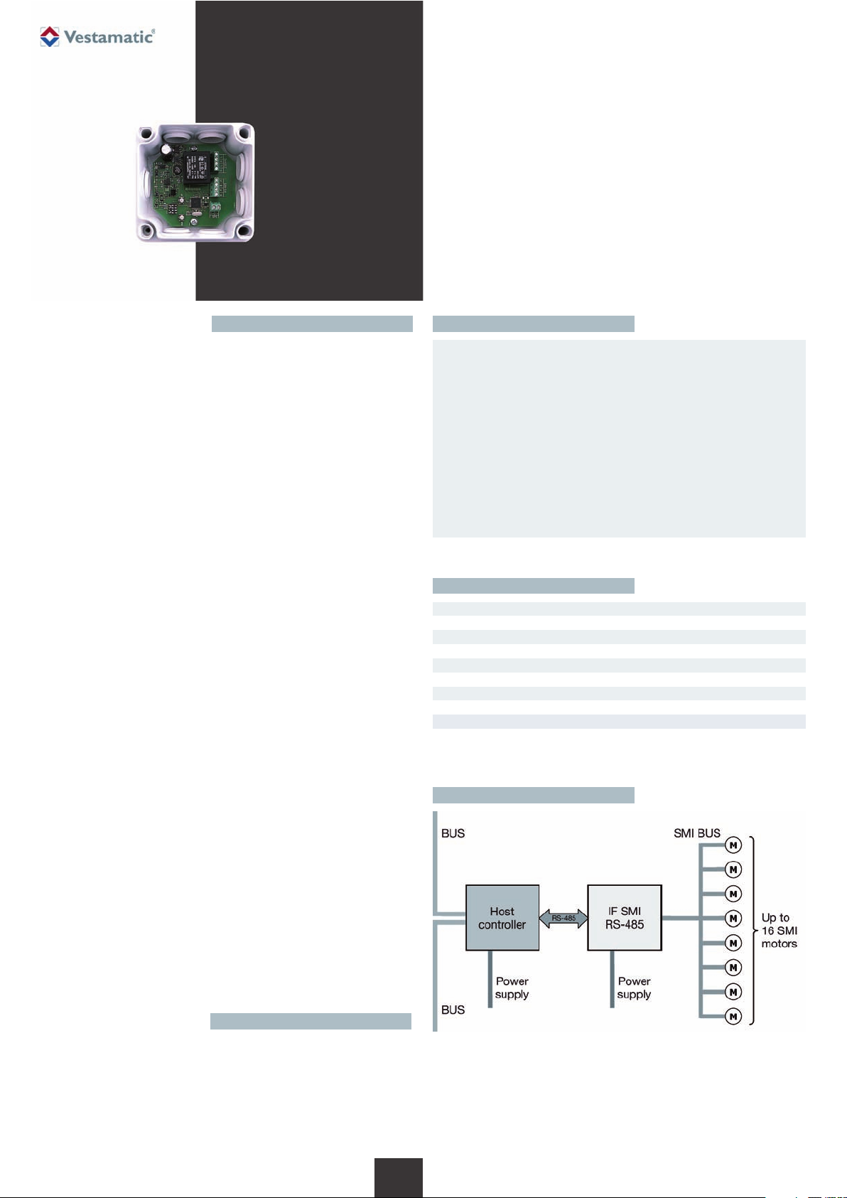
4.1.5 Base Address
The IF SMI RS-485 is selected by its base address. Each IF SMI RS-485
module connected to a shared RS-485 BUS must have an unique base
address. A maximum of 16 IF SMI RS-485 modules can be connected to
the same RS-485 BUS, which makes it possible to control 16 x 16 = 256
SMI motors.
5.2 CRC16 Calculation
Example code CRC16 calculation in C-language:
#define CRC_CONSTANT 0xA001
word Crc16 (byte* pb, byte len)
{
byte i;
word crc;
for (crc=0xffff; len--; pb++)
{
crc ^= (byte)*pb;
for (i=8; i--; )
if (crc & 0x01)
{
crc >>= 1;
crc ^= CRC_CONSTANT;
}
else
crc >>= 1;
}
// return crc result
return crc;
}
5. Protocol
This chapter describes the communication protocol between the IF SMI RS-485
module and Host controller.
4.2 Termination RS-485 BUS
A terminating resistor is simply a resistor placed at the extreme end or
ends of a cable. The value of the terminating resistor is ideally the same
value as the characteristic impedance of the cable.
5.1 Message structure
[SID] [LEN] [CMD] [DATA] [CRC16]
SID Slave ID
LEN Message length (without CRC)
CMD Command byte
DATA Optional data bytes
CRC16 16 bits checksum (LSB first)
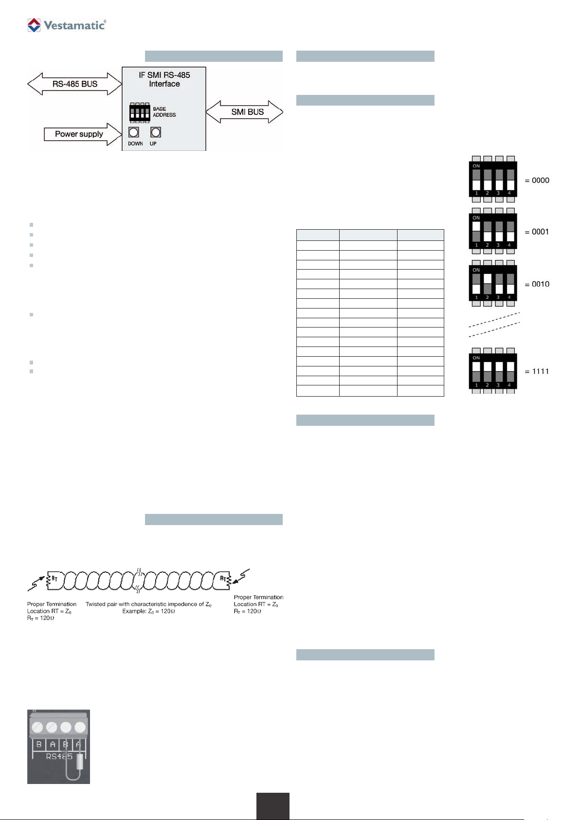
The IF SMI RS-485 module has 4 DIP
switches, which represents the base
address of the module from 0 to 15 (decimal)
or 0 to F (hexadecimal). The base address
is part of the Slave ID:
DIP switch Base address Slave ID
0000 0 0xC0
0001 1 0xC1
0010 2 0xC2
0011 3 0xC3
0100 4 0xC4
0101 5 0xC5
0110 6 0xC6
0111 7 0xC7
1000 8 0xC8
1001 9 0xC9
1010 10 0xCA
1011 11 0xCB
1100 12 0xCC
1101 13 0xCD
1110 14 0xCE
1111 15 0xCF
As a general rule moreover, termination resistors should be placed at both
far ends of the cable. Although properly terminating both ends is absolutely critical for most system designs, it can be argued that in one special
case only one termination resistor is needed. This case occurs in a system
when there is a single transmitter and that single transmitter is located at
the far end of the cable. In this case there is no need to place a termination resistor at the end of the cable with the transmitter, because the signal
is intended to always travel away from this end of the cable.
There is a Terminating resistor with a value of 120B
delivered by every IF SMI RS-485 module. If the
Terminating resistor is recommended than he must be
placed between the A and B from the connector on
the PCB.
5.3 Steer commands
#define MSG_UP 0x10
#define MSG_DOWN 0x11
#define MSG_STOP 0x12
#define MSG_STEP_UP 0x13
#define MSG_STEP_DOWN 0x14
#define MSG_SET_POS 0x15
#define MSG_SET_TILT 0x16
#define MSG_SET_POS_STEP_UP 0x17 (Software V10D or higher)
#define MSG_SET_POS_STEP_DOWN 0x18 (Software V10D or higher)
#define MSG_GOTO_POS1 0x19 (Software V10E or higher)
#define MSG_GOTO_POS2 0x1A (Software V10E or higher)
4.1 Overview IF SMI RS-485
The IF SMI RS-485 module is an intelligent module that translates RS-485
commands to SMI commands.
2/ 7
G

© Vestamatic GmbH
Art.-Nr.: 85301221 E1 • Vestamatic GmbH • Dohrweg 27 • D-41066 Mönchengladbach • www.vestamatic.com
IF SMI RS-485
5.3.6 MSG_SET_POS
This message is used to move all, or a set of sun blind, to an absolute
position.
Message: [SID] / [LEN] / [CMND] / [MSK0] / [MSK1] / [POS0] / [POS1] /
[CRC16]
[MSK0]: LSB of 16-bit mask to select motor address 0..7.
[MSK1]: MSB of 16-bit mask to select motor address 8..16.
[POS0]: LSB of 16-bit absolute position.
[POS1]: MSB of 16-bit absolute position.
The absolute position value is defined as below:
0x0000 is the top position (0%).
0x8000 is the middle position (50%).
0xFFFF is the bottom position (100%).
The IF SMI RS-485 module responds to this request with a general status
message MSG_GETGENSTA
T.
The position of each sun blind can be obtained by the detailed response
message MSG_GETDETSTAT.
5.3.7 MSG_SET_TILT
This message is used to move all, or a set of venetian blinds, in a absolute
tilt orientation.
Message: [SID] / [LEN] / [CMND] / [MSK0] / [MSK1] / [TILT] / [CRC16]
[MSK0]: LSB of 16-bit mask to select motor address 0..7.
[MSK1]: MSB of 16-bit mask to select motor address 8..16.
[TILT]: Absolute tilt orientation (0..255).
Absolute tilt orientation is defined as follow:
127 (0x7F) slats completely closed in down direction
0 (0x00) slats completely open (horizontal)
-128 (0x80) slats completely closed in up direction
The IF SMI RS-485 module responds to this request with a general status
message MSG_GETGENSTA
T.
The position of each sun blind can be obtained by the detailed response
message MSG_GETDETSTAT.
Remark: The MSG_SET_TILT message uses a manufacturer specific SMI
command, which is currently only supported by Vestamatic
SMI motors.
5.3.8 MSG_SET_POS_STEP_UP
This message is used to move all, or a set of venetian blinds, to an absolute
position combined with an relative up command.
Message: [SID] / [LEN] / [CMND] / [MSK0] / [MSK1] / [POS0] / [POS1] /
[NSTEP] / [CRC16]
[MSK0]: LSB of 16-bit mask to select motor address 0..7.
[MSK1]: MSB of 16-bit mask to select motor address 8..16.
[POS0]: LSB of 16-bit absolute position.
[POS1]: MSB of 16-bit absolute position.
[NSTEP]: Number of steps (1..255) in UP direction. 1 step is defined as
2º rotation of the output shaft of the SMI motor.
The IF SMI RS-485 module responds to this request with a general status
message MSG_GETGENSTA
T. The position of each sun blind can be
obtained by the detailed response message MSG_GETDETSTAT.
5.3.9 MSG_SET_POS_STEP_DOWN
This message is used to move all, or a set of venetian blinds, to an absolute
position combined with an relative down command.
Message: [SID] / [LEN] / [CMND] / [MSK0] / [MSK1] / [POS0] / [POS1] /
[NSTEP] / [CRC16]
[MSK0]: LSB of 16-bit mask to select motor address 0..7.
[MSK1]: MSB of 16-bit mask to select motor address 8..16.
[POS0]: LSB of 16-bit absolute position.
[POS1]: MSB of 16-bit absolute position.
[NSTEP]: Number of steps (1..255) in DOWN direction. 1 step is defined
as 2º rotation of the output shaft of the SMI motor.
The IF SMI RS-485 module responds to this request with a general status
message MSG_GETGENSTAT. The position of each sun blind can be
obtained by the detailed response message MSG_GETDETSTAT.
Subject to modifications.
5.3.1 MSG_UP
This message is used to move all, or a set of sun blind, to the top position.
Message: [SID] / [LEN] / [CMND] / [MSK0] / [MSK1] / [CRC16]
[MSK0]: LSB of 16-bit mask to select motor address 0..7.
[MSK1]: MSB of 16-bit mask to select motor address 8..16.
When bit n in mask is set, SMI motor with address n is addressed and
e
xecutes a UP command.
The IF SMI RS-485 module responds to this request with a general status
message MSG_GETGENSTAT.
The position of each sun blind can be obtained by the detailed response
message MSG_GETDETSTAT.
5.3.2 MSG_DOWN
This message is used to move all, or a set of sun blind, to the lower position.
Message: [SID] / [LEN] / [CMND] / [MSK0] / [MSK1] / [CRC16]
[MSK0]: LSB of 16-bit mask to select motor address 0..7.
[MSK1]: MSB of 16-bit mask to select motor address 8..16.
When bit n in mask is set, SMI motor with address n is addressed and
e
xecutes a DOWN command.
The IF SMI RS-485 module responds to this request with a general status
message MSG_GETGENSTAT.
The position of each sun blind can be obtained by the detailed response
message MSG_GETDETSTAT.
5.3.3 MSG_STOP
This message is used to stop all, or a set of sun blind.
Message: [SID] / [LEN] / [CMND] / [MSK0] / [MSK1] / [CRC16]
[MSK0]: LSB of 16-bit mask to select motor address 0..7.
[MSK1]: MSB of 16-bit mask to select motor address 8..16.
The IF SMI RS-485 module responds to this request with a general status
message MSG_GETGENSTA
T.
The position of each sun blind can be obtained by the detailed response
message MSG_GETDETSTAT.
5.3.4 MSG_STEP_UP
This message is used to relatively move all, or a set of sun blind, in UP
direction.
Message: [SID] / [LEN] / [CMND] / [MSK0] / [MSK1] / [NSTEP] / [CRC16]
[MSK0]: LSB of 16-bit mask to select motor address 0..7.
[MSK1]: MSB of 16-bit mask to select motor address 8..16.
[NSTEP]: Number of steps (1..255) in UP direction. 1 step is defined as
2° rotation of the output shaft of the SMI motor.
The IF SMI RS-485 module responds to this request with a general status
message MSG_GETGENSTA
T.
The position of each sun blind can be obtained by the detailed response
message MSG_GETDETSTAT.
5.3.5 MSG_STEP_DOWN
This message is used to relatively move all, or a set of sun blind, in DOWN
direction.
Message: [SID] / [LEN] / [CMND] / [MSK0] / [MSK1] / [NSTEP] / [CRC16]
[MSK0]: LSB of 16-bit mask to select motor address 0..7.
[MSK1]: MSB of 16-bit mask to select motor address 8..16.
[NSTEP]: Number of steps (1..255) in DOWN direction. 1 step is defined
as 2° rotation of the output shaft of the SMI motor.
The IF SMI RS-485 module responds to this request with a general status
message MSG_GETGENSTA
T.
The position of each sun blind can be obtained by the detailed response
message MSG_GETDETSTAT.
3/ 7
G
 Loading...