

Vestamatic IF SMI RS-485 DIN RAIL Series, IF SMI RS-485 24 VDC-DIN, IF SMI RS-485 230 VAC-DIN Installation And Operating Instructions Manual
G
IF SMI RS-485 DIN
3060 001 GB 4518 A06
1. What is SMI?
2. Safety precautions
3. Technical data
4. Hardware
4.1 Overview IF SMI RS-485
4.1.1 RS-485 User interface
4.1.2 RS-485 BUS
4.1.3 Power supply
4.1.4 SMI BUS
4.1.5 Master Up/Down button
4.1.6 Base Address
4.2 Termination RS-485 BUS
5. Menu navigation
5.1 Power-up
5.2 Main menu
5.3 Menu navigation
5.4 Address menu
5.5 Modify base address
5.6 Show error
5.7 Error log menu
5.8 Soft RESET
6. Protocol
6.1 Message structure
6.2 CRC16 Calculation
6.3 Steer commands
6.3.1 MSG_UP
6.3.2 MSG_DOWN
6.3.3 MSG_STOP
6.3.4 MSG_STEP_UP
6.3.5 MSG_STEP_DOWN
6.3.6 MSG_SET_POS
6.3.7 MSG_SET_TILT
6.3.8 MSG_SET_POS_STEP_UP
6.3.9 MSG_SET_POS_STEP_DOWN
6.3.10 MSG_GOTO_POS1
6.3.11 MSG_GOTO_POS2
6.3.12 MSG_GETMANID
6.3.13 MSG_SMI_TUNNEL
6.3.14 MSG_GW_OPTIONS
6.3.15 MSG_ERROR
6.4 Maintenance commands
6.4.1 MSG_VERSION
6.4.2 MSG_AUTO_ADDR
6.4.3 MSG_GET_SER
6.4.4 MSG_SET_SMIID
6.4.5 MSG_GET_PAR
6.4.6 MSG_GET_POS1
6.4.7 MSG_SET_POS1
6.4.8 MSG_GET_POS2
6.4.9 MSG_SET_POS2
6.5 Status commands
6.5.1 MSG_GETGENSTAT
6.5.2 MSG_GETDETSTAT
7. PC Test Software
7.1 Communication
7.2
General commands
7.3
Motor Mask based commands
7.4 Motor ID based commands
7.5 Send / Receive
8. Wiring diagrams
8.1 IF SMI RS-485 LoVo
8.2 IF SMI RS-485 230VAC
IF SMI RS-485 DIN RAIL
Contents
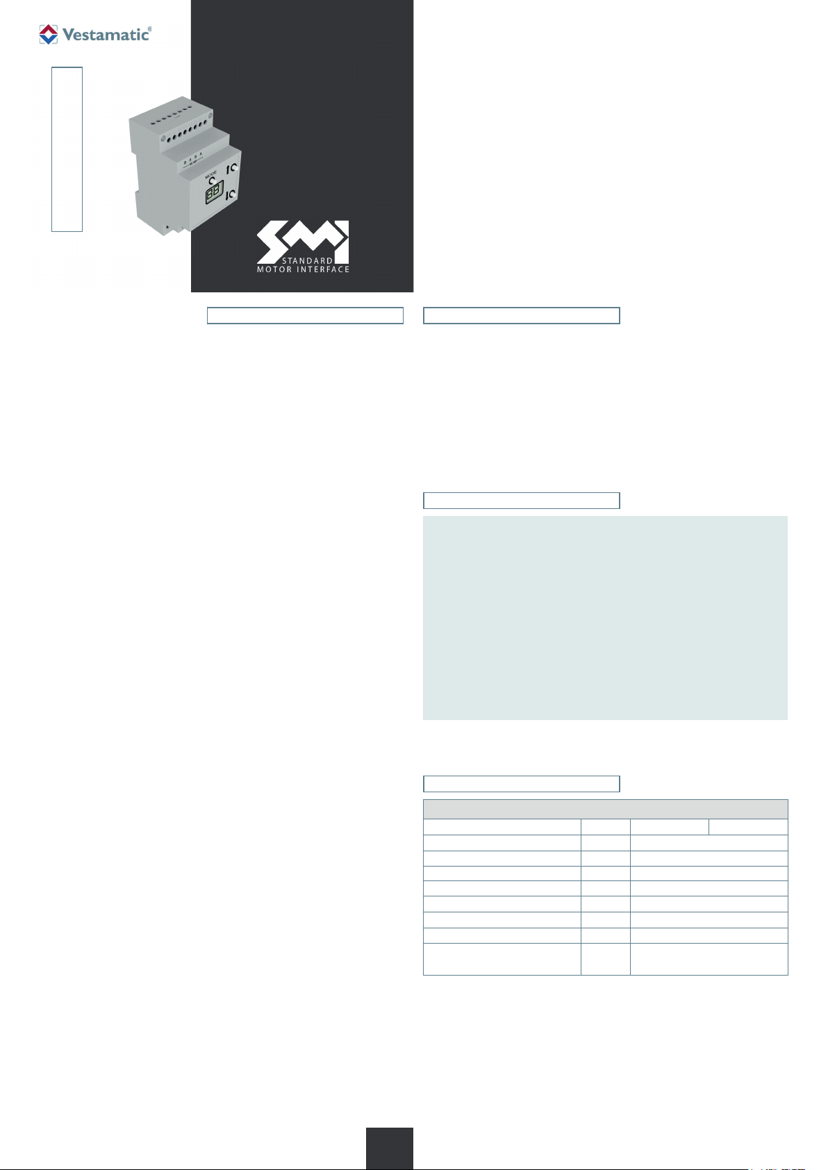
IF SMI RS-485 24 VDC-DIN
Motor control SMI RS-485 for top-hat rail
for control of 16 SMI motors 24 VDC.
Art.-no.: 01092124
IF SMI RS-485 230 VAC-DIN Art.-no.: 01092714
Motor control SMI RS-485 for top-hat rail
for control of 16 SMI motors 230 VAC.
Installation and Operating Instructions
1. What is SMI?
SMI is the abbreviation for Standard Motor Interface. SMI has been developed for the connection of intelligent drives for roller shutters and
sun protection systems. SMI enables to transmit telegrams from control
system to the drive and vice versa. With SMI it is possible to combine
products from different sources together. The SMI Interface should spread
high value solutions and promote drives and controls on the market. The
applications in roller shutters and sun protection systems require extreme
robustness and economic efficiency. SMI has been developed to meet
these requirements.
2. Safety precautions
– Contact a professional electrician for installation.
Ä
– Check the control system for signs of mechanical damage after
unpacking. If you notice any shipping damage, do not start up
the control system and notify your supplier imme di ately.
– The control system should only be used for the purpose speci-
– If the control unit cannot be operated without presenting a
– Turn off the power supply and prevent it from being switched
Article
Supply voltage: 230 VAC
Impulse voltage withstand level: kV 2.5
Rated power: W 2 W
Operating temperature: °C 0 °C (32 °F) to +40 °C (104 °F)
IP class: IP 20
Degree of contamination: 2
Dimensions (H × W × D): mm 90 × 52 × 60 (3 HP)
Conformity:
fied by the manufacturer (refer to the operating instructions).
Any changes or modifications thereof are not permissible and
will result in loss of all warranty claims.
hazard, it must be switched off and prevented from being
switched on unintentionally.
on unintentionally before performing work on any windows,
control or sunshades driven by the control system.
3. Technical data
IF SMI RS-485 DIN
Art.-no.: 01092124 01092714
p
Art.-Nr.: 3060 001 GB 4518 A06 • Vestamatic GmbH • Dohrweg 27 • D-41066 Mönchengladbach • www.vestamatic.com
1/10
G
Subject to modifications.© Vestamatic GmbH
IF SMI RS-485 DIN
4. Hardware
The IF SMI RS-485 can be used for SMI (230VAC) or SMI LoVo applications.
Important: It is not allowed to use a combination of SMI (230VAC) and
SMI LoVo on the same SMI BUS.
4.1 Overview IF SMI RS-485
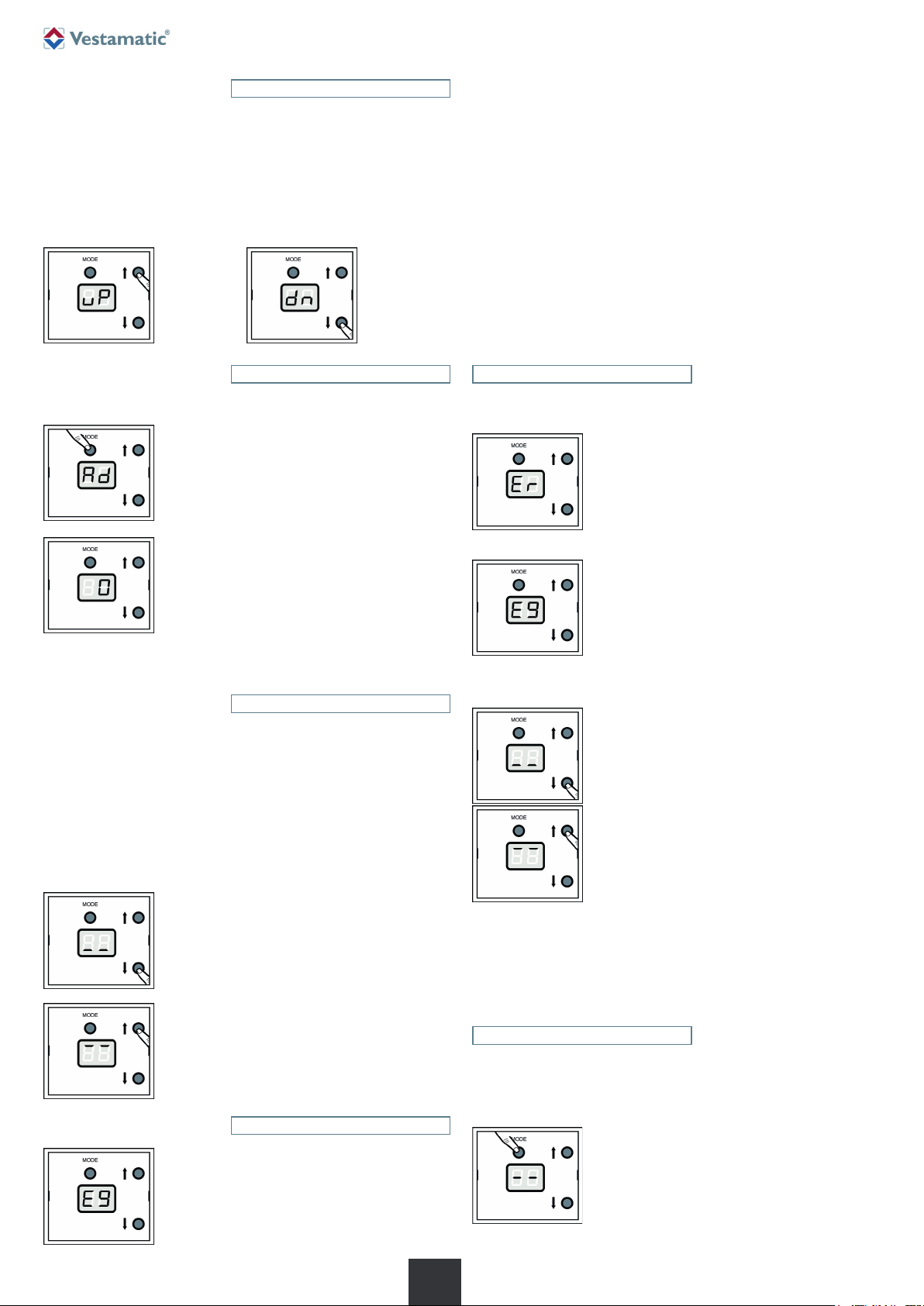
4.2 Termination RS-485 BUS (Optional)
If you experience problems, please read this section.
The device usually has sufficient base termination. In exceptional cases
(e.g. with long or untwisted lines) we recommend to use a terminating
resistor of 120 Ω at both ends of the bus line.
This is to be installed between terminals A and B of the RS-485 signal line.
A terminating resistor is simply a resistor placed at the extreme end or
ends of a cable. The value of the terminating resistor is ideally the same
value as the characteristic impedance of the cable.
As a general rule moreover, termination resistors should be placed at both
far ends of the cable. Although properly terminating both ends is absolute ly critical for most system designs, it can be argued that in one special
case only one termination resistor is needed. This case occurs in a system
when there is a single transmitter and that single transmitter is located at
the far end of the cable. In this case there is no need to place a termination
resistor at the end of the cable with the transmitter, because the signal is
intended to always travel away from this end of the cable.
There is a Terminating resistor with a value of 120B
delivered by every IF SMI RS-485 module. If the Terminating resistor is recommended than he must be
placed between the A and B from the connector on
the PCB.
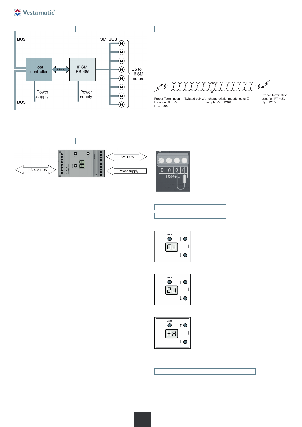
The IF SMI RS-485 module is an intelligent module that translates RS-485
commands to SMI commands.
4.1.1 RS-485 User interface
MODE button
– Short press Show current base address for 5 sec.
– Long press Modify current base address
– Double press Show error log
UP/DOWN button
– In main menu Steer all attached SMI motors UP/DOWN.
– In address menu Increase/Decrease base address
– Error log menu Show next/previous error
4.1.2 RS-485 BUS
The communication BUS between Host controller and IF SMI RS-485 module is RS-485. The following configuration is used:
Baud rate: 19200
Data bits: 8
Stop bits: 1
Parity: None
Signal: -7V to +10V Common-Mode Input Voltage Range
Maximum allowed pause Byte-to-Byte: 5 milliseconds
4.1.3 Power supply
The IF SMI RS-485 module needs the following power supply signals:
L, N (230VAC/50Hz)
4.1.4 SMI BUS
The SMI bus exists out of the following signals:
I+ (SMI BUS)
I
-
(SMI BUS)
5. Menu navigation
5.1 Power-up
During power-up, the firmware version is shown in 3 stages:
Step 1
Display shows “F-“ for 2 sec as indication that firmware version follows.
Step 2
Display shows firmware version (major.minor) for
3 seconds.
Step 3
Display shows firmware revision for 2 seconds.
4.1.5 Master Up/Down button
The IF SMI RS-485 has an master UP/DOWN button, to operate all
connected SMI motors at simultaneously.
4.1.6 Base Address
The IF SMI RS-485 is selected by its base address. Each IF SMI RS-485
module connected to a shared RS-485 BUS must have an unique base
address. A maximum of 16 IF SMI RS-485 modules can be connected to
the same RS-485 BUS, which makes it possible to control 16 x 16 = 256
SMI motors.
2/10
G
5.2 Main menu
The main menu is the default menu that is being shown when no other
user actions take place. The main menu shows:
A counter – counting the number of correctly received RS-485 frames
from 0 up to 99 and then starts at 0 again.
A blinking dot in the right bottom corner with a blink-frequency of 1 Hz
to indicate a running application.
Subject to modifications.© Vestamatic GmbH
Art.-Nr.: 3060 001 GB 4518 A06 • Vestamatic GmbH • Dohrweg 27 • D-41066 Mönchengladbach • www.vestamatic.com
IF SMI RS-485 DIN
5.3 Menu navigation
When the UP or DOWN buttons in the main menu are pressed, all attached
SMI motors will move UP or DOWN (depends on the pressed button) as
long as the button is pressed. This feature is useful during commissioning
to check:
– if the SMI communication is working
– if all attached motors are running in the correct direction
– if the limit positions are set correctly
Display shows the following as a visual feedback:
UP button
pressed
5.4 Address menu
The current RS-485 base address is shown when the MODE button is
pressed shortly (< 5 sec).
As long as the MODE button is pressed shortly,
“Ad” is shown on the display.
DOWN button
pressed
Error code description:
E0 = no error
E1 = RS-485 framing error
E2 = RS-485 timing error
E3 = RS-485 data overflow error
E4 = RS-485 CRC error
E5 = RS-485 command error (not supported or invalid length)
E6 = RS-485 busy (not able to process new command)
E7 = SMI format error
E8 = SMI checksum error
E9 = SMI timing error
EA = SMI data overflow
EB = SMI echo error
EC = SMI queue full error
The error message is shown for 5 seconds. Pressing any buton returns to
main menu directly.
5.7 Error log menu
The error log keeps track of the 5 last occurred errors, and can be shown
be pressing the MODE button twice within 1 second.
The text “Er” is briefly visible to indicate that the error
log is shown.
When the MODE button is released, the current
RS-485 base address is shown for 5 sec.
To directly return to the main menu, the MODE button must be pressed
again.
5.5 Modify base address
The current RS-485 base address can be modified be pressing the
MODE button for more than 5 seconds (after 5 seconds the text “Ad” starts
blinking).
After the MODE button is released, the current RS-485 base address is
shown blinking.
– Pressing UP will increase the RS-485 base address.
– Pressing DOWN will decrease the RS-485 base address.
– Pressing MODE button – or wait for 5 seconds – will store the RS-485
base address and return to main menu.
The RS-485 base address can be modified from 0 to 15.
When pressing the DOWN button while base address is already 0, the following is shown to indicate
that the base address cannot be further decreased.
When pressing the UP button while the base address
is already 15, the following is shown to indicate that
the base address cannot be further increased.
5.6 Show error
Next, the last occurred error is shown blinking.
– By pressing the UP button, the previous occurred error will be shown.
– By pressing the DOWN button, the next occurred error will be shown.
When pressing DOWN button while first error in log
is currently being shown..
When pressing UP button while last error in log is
currently shown.
By briefly pressing MODE button – or waiting for a few seconds – you will
return back to main menu.
5.8 Soft RESET
The IF SMI RS-485 can be restarted (soft-reset) without interruption of the
power supply by pressing the MODE button for 10 seconds.
After 10 seconds pressing the MODE button, the soft-reset will be entered,
and display will briefly show the following:
When an error occurs,
this will be shown directly.
3/10
G
Art.-Nr.: 3060 001 GB 4518 A06 • Vestamatic GmbH • Dohrweg 27 • D-41066 Mönchengladbach • www.vestamatic.com
Subject to modifications.© Vestamatic GmbH
 Loading...