

Vestamatic IF SMI KNX 24VDC Installation And Operating Instructions Manual
Art.-Nr.: 84501110 E1 • Vestamatic GmbH • Dohrweg 27 • D-41066 Mönchengladbach • www.vestamatic.com
Subject to modifications.© by Vestamatic GmbH
IF SMI KNX
24VDC
Art.-no.:
01092510
Installation and Operating Instructions
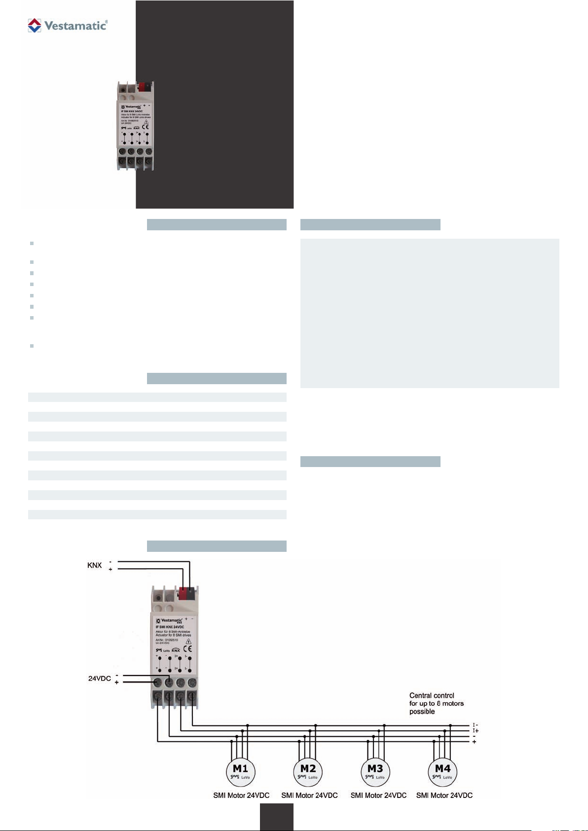
IF SMI KNX 24VDC Art.-no.: 01092510
Intelligent motor control for 8 SMI LoVo motors.
Option of connecting up to 8 SMI LoVo 24VDC motors to
control interior blinds and interior motors
Compatible with KNX BUS system
Programmable button and LED for addressing indication on the device
KNX objects, Up/Down, Step/Stop, shading position, automatic
Shutter height %, slat %, shutter height status %, slat status %
Store/Call up scene 1+2, drive status
Individual and group control via KNX output devices
(conform EIS7 Standard or DPT 1.007 and 1.008 described in KNX
System Specifications Interworking Datapoint Types)
Fully synchronised operation of shades also possible in parallel
connection
Short description
Technical data
1/ 15
G
Safety precautions
– Contact a professional electrician for installation.
– Check the control system for signs of mechanical damage after
unpacking. If you notice any shipping damage, do not start up
the control system and notify your supplier immediately.
– The control system should only be used for the purpose speci-
fied by the manufacturer (refer to the operating instructions).
Any changes or modifications thereof are not permissible and
will result in loss of all warranty claims.
– If the control unit cannot be operated without presenting a
hazard, it must be switched off and prevented from being
switched on unintentionally.
– Turn off the power supply and prevent it from being switched
on unintentionally before performing work on any windows,
control or sunshades driven by the control system.
Ä
Supply voltage: 24VDC
Housing: REG 2TE
Interface for BUS system: KNX, Medium TP1
Interface for motor: SMI
Communication projects: 82
Max. number of group addresses: 114
Max. assignment of group addresses: 162
Operating temperature: 0 °C (32 °F) to +40 °C (104 °F)
Software class: A
IP class: IP 20
Degree of contamination: 2
Dimensions (L × W × D): 90 × 35 × 59 mm
Mark of conformity: p
Notes for professional electricians
1. Connect the control in accordance with the wiring diagram.
2. Attach module on the top-hat rail and push until the module audibly clicks
into place on the mounting rail.
Installation
Wiring diagram

© Vestamatic GmbH
Art.-Nr.: 84501110 E1 • Vestamatic GmbH • Dohrweg 27 • D-41066 Mönchengladbach • www.vestamatic.com
IF SMI KNX 24VDC
Subject to modifications.
Contents General functional description
What is SMI? 17
General functional description 17
Software and functions 17
Operating states 18
State administration and state table 18
Travel command lock 18
Safety 18
Manual mode 18
Automatic mode 18
State table 19
ETS interface 20
ETS communication objects 21
“Safety” object 22
“Travel command lock” object 22
“Up/Down travel, channel x” object (manual mode) 22
“Stop/Step travel, channel x” object (manual mode) 22
“Sunshade, channel x” object (automatic mode) 22
“Automatic mode, channel x” object 22
“Position of sunshade (%), channel x” object
(automatic mode or, if automatic deactivated, manual mode) 22
“Position of slat angle (%), channel x” object
(automatic mode or, if automatic deactivated, manual mode –
only for blinds) 22
“Status position of sunshade (%), channel x” object 22
“Status position of slat angle (%), channel x” object
(only for blinds) 23
“Move to scene pos1/pos2, channel x” object
(manual mode) 22
“Save scene pos1/pos2, channel x” object (manual mode) 23
“Drive error status” object 23
ETS parameters 23–27
Planning and activation 27
Initialisation using drives with slave addresses already
programmed 27
Initialisation using drives with non-programmed slave
addresses or slave address 0 27
Errors and warnings during initialisation 28
Procedure for planning and activation 28
Options in the case of errors during planning and activation 28
User interface objects and properties (UIO interface) 28
Errors and warnings in properties 201 & 202
in the device object 28
User interface object 50001 and properties therein 29
Property 1, 51, 64 and 65 h 29
Property 80, 81 to 88 30
The SMI software 30
SMIdrive 8 is an EIB actuator for the control of up to 8 SMI drives. The
drives are independently addressed and controlled via the SMI.The drives
are controlled depending on the parametrisation of the actuator and commands received via the EIB. Commands and data are transmitted via the
EIB using communication objects.Thus the drives connected to the actuator can be moved independently via the EIB using standard functions such
as up/down, step/stop and others. Also, status information such as current
shade or slat position (%) and motor errors can be interrogated via the
EIB. A determination of prioritised operating states integrates manual and
automatic operations as well as those controlled by safety monitors or travel
locks.
The parametrisation and activation of the device is carried out via the ETS.
The ETS interface presents the project manager with parameters arranged in tabs. The communication objects are tabulated. The addressing
of the SMI drives connected to the device is carried out via the ETS activation. The addressing of the drives on the SMI side is either carried out
automatically using the slave addresses assigned in the ETS parametrisation or alternatively using SMI key IDs given in the ETS.
On the SMI side, the actuator only uses commands from the SMI standard
and is thereby compatible with SMI drives from all manufacturers. The
actuator does not functionally support use of manufacturer-specific features. Nevertheless, manufacturer-specific parametrisation of SMI drives
can also be carried out via the EIB (see following section).
In addition to ETS parametrisation, a UIO (user interface object) interface
can be used in order to obtain access to the internal actuator SMI configuration or directly to the SMI communication via the EIB. Software is
available for the practical use of this interface. It is, however, in principle
also possible to use this interface with, for instance, the device editor from
the ETS3 packet. The UIO interface permits further diagnostics within the
context of activation and also subsequent interventions in the parametrisation of SMI drives themselves.
Software and functions
The software of the SMI actuator consists of different units, which divide
into the resources available in the actuator hardware (a processor with
integrated Flash ROM, RAM and additional EEPROM).
The EIB operating system of the actuator “System 2” is compatible with
the BCU2 standard. It provides the entire interface for hardware resources
and applications software (firmware) on the one hand and for EIB on
the other. A bootloader in the Flash-ROM of the processor is an integral
component of System 2 and permits an exchange of software parts,
especially firmware (this is the applications software including SMI
communications library) through access via the EIB. The firmware is
mirrored in a copy in the EEPROM. Only firmware recognised as valid
is copied by the bootloader from the EEPROM into the processor Flash
ROM and, if appropriate, implemented.
An SMI communications library is an integral component of the firmware. It is certified on the part of SMI and constitutes the interface to
the SMI and the slaves connected to it.
The actual applications software uses the remaining actuator memory
for the actuator software functionality depending on ETS parametrisation. It also includes the operation of the UIO interface via standardised
system functions.
The ETS interface includes information on EIB communication objects
and parameters, which specify the interface with the EIB and the
functionality of the actuator. These elements can be configured and
loaded into the actuator using the ETS.This information thereby reaches
the EEPROM of the actuator and can be read there by the operating
system and by the firmware and be evaluated in detail to determine the
performance.
Different software tools permit access to specific memories of the actuator
via the EIB. In addition to standard development tools, these tools are
namely a firmware update tool, which under certain conditions permits an
update of the firmware via the EIB, as well as an SMI tool, which using the
UIO interface supports diagnoses and direct access to the SMI via a gateway.
The functionality of the firmware and the elements of the ETS surface are
firstly described below. Other sections will explain specifics on the activation and the UIO interface.
2/ 15
G
SMI is the abbreviation for Standard Motor Interface. SMI has been developed for the connection of intelligent drives for roller shutters and sun
protection systems. SMI enables to transmit telegrams from control
system to the drive and vice versa. With SMI it is possible to combine
products from different sources together.The SMI Interface should spread
high value solutions and promote drives and controls on the market. The
applications in roller shutters and sun protection systems require extreme
robustness and economic efficiency. SMI has been developed to meet
these requirements.
What is SMI?

Subject to modifications.© Vestamatic GmbH
Art.-Nr.: 84501110 E1 • Vestamatic GmbH • Dohrweg 27 • D-41066 Mönchengladbach • www.vestamatic.com
IF SMI KNX 24VDC
State administration and state table
The actuator basically distinguishes between the following states (in order
of decreasing priority):
1) Travel command lock
2) Safety
3) Manual mode
4) Automatic mode
The automatic mode can be locked separately for each channel per ETS
parameter. In this case, the communication objects for switching between
automatic and manual mode and the sunshade objects do not appear.The
objects for positioning shade height and slat angle (%) are considered as
manual mode objects for all those channels for which the automatic mode
is locked; otherwise, they are considered as automatic objects.
The last state, which exists before a disconnection of the (EIB) bus voltage,
is restored when the bus voltage is switched back on.
Travel command lock
This state has the highest priority. It prevents all other movements, even
those due to a safety object.The purpose of setting a travel command lock
is, for example, to protect people who carry out work on automatically
moveable shades (window cleaners).
By activating the travel command lock, any ongoing movement of the
shade is still followed through; any movement-triggering telegrams that
arrive thereafter are no longer executed however.
As long as the travel command lock is active, one of the other states is
“masked” active in the background. By lifting the travel command lock, the
“masked” state is restored and in case of safety or automatic mode the
corresponding movement is also activated if appropriate. The “masked”
state is either the last one that existed before activation of the travel command lock or one which was observed by an interim telegram in the background.
If when activating the travel command lock, the actuator is, for example, in
automatic mode, incoming automatic travel commands are also stored
during the travel command lock and executed after it is lifted. If a safety
object with a “1” value occurs during the travel command lock, the
“masked” state changes into “Safety” and results in the corresponding
movement as soon as the travel command lock is lifted.
Manual mode commands, which occur during a travel command lock, are
ignored and do not result in a “masked” change in state either.
Safety
This state has the second highest priority.If a safety object with a “1” value
occurs, the state of the actuator changes into “Safety” mode (in the event
of existing travel command lock of the “masked” state). If there is no travel
command lock, the drive moves to the respective channel’s parametrised
position for this case. The purpose of the “Safety” state is to protect the
shades against wind that is too strong, for example.
By activating the safety function, any ongoing movement of the shade is
interrupted and any incoming movement-triggering telegrams are no longer
executed.
As long as the safety mode is active, one of the automatic or manual mode
states is “masked” active in the background. By lifting the safety state, the
“masked” state is restored and in case of automatic mode the corresponding movement is also activated if appropriate. The “masked” state is the
last one which existed before activation of the safety function.
Automatic travel commands, which occur in the safety state, are observed
and only executed if safety mode and potentially command lock or manual
mode are overridden.
Manual mode commands, which occur while in a “Safety” state, are ignored
and do not result in a “masked” change in state either.
For those channels for which the automatic mode was deactivated per
parameter, an additional parameter can be set for each channel. This
parameter can determine that even those positions, which were specified
by manual mode-% objects, are restored, after the safety function is discontinued, to how they were before the safety function, or to how they
were preset in the “masked” state while the safety function was still active.
In the state table on the next page, reference is made to this information
in the “Safety off in manual mode without travel lock” field.The corresponding parameter appears in the parameter description.
If the actuator receives a telegram to activate the travel command lock
while the safety function is active, the state switches to travel command
lock and the “Safety” state is “masked”.
Manual mode
This state has the third highest priority. Unless prevented by the travel
command lock or safety function, manual commands are executed immediately and also result in a change in state in manual mode in the case of
existing automatic mode. A change of manual mode to automatic mode
can only be carried out using the automatic object with the value “1”.
Automatic mode
This state has the lowest priority. Automatic travel commands are only executed in automatic mode.
3/ 15
G
Operating states
© Vestamatic GmbH
Art.-Nr.: 84501110 E1 • Vestamatic GmbH • Dohrweg 27 • D-41066 Mönchengladbach • www.vestamatic.com
IF SMI KNX 24VDC
Subject to modifications.
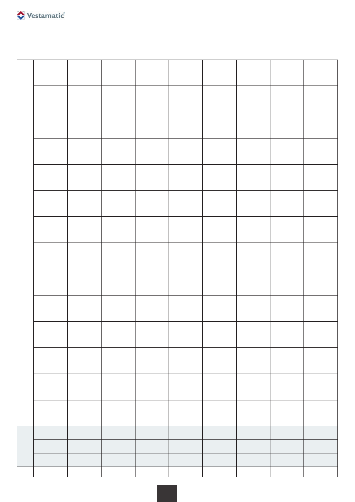
State table
The following state table reproduces the transitions between the operating states depending on events occurring (telegrams).
The manual mode state exists if all other operating states (automatic, safety and travel lock) are switched off.
4/ 15
G
No.
Travel
lock
Safety
Auto-
matic
EIB
OFF
EIB
ON
Travel lock
ON
object
Travel lock
OFF
object
Safety ON
object or
time
monitoring
“Safety”
object
OFF
“Automatic”
object
ON
“Automatic”
object
OFF
“Manual
mode”
object
UP/DOWN
“Manual
mode”
object
Step
UP/DOWN
Move
to scene
object
Save
scene
object
(motor
stands)
Shade/slat
% position
object
Up/sun-
shade
object
(see note)
0 off off off
0
Move to
position for
Bus OFF
0 4
Bring
current
movement
to end
0 2
Move to
safety
position
0 1
Move to
stored
shade/
slat position
0 0
Up and
down
0
Step up
and down
0
Move to
scene
0
Save scene
0
Setpoint
position is
only stored
0
Setpoint
position is
only stored
1 off off on
1
Move to
position for
Bus OFF
1
Move to
stored
shade/slat
position
5
Bring
current
movement
to end
1 3
Move to
safety
position
1 1 0 0
Up and
down
0
Step up
and down
0
Move to
scene
1
Save scene
1
Movement to
and storage
of setpoint
position
1
Movement to
and storage
of setpoint
position
2
off
on off
2
Move to
position for
Bus OFF
2
Move to
safety
position
6
Bring
current
movement
to end
2 2 0
See comment
re. safety
operating
states
3 2 2 2 2 2
Save scene
2
Setpoint
position is
only stored
2
Setpoint
position is
only stored
3
off
on
on
3
Move to
position for
Bus OFF
3
Move to
safety
position
7
Bring
current
movement
to end
3 3 1
Move to
stored
shade/
slat position
3 2 2 2 2 3
Save scene
3
Setpoint
position is
only stored
3
Setpoint
position is
only stored
4
on off off
4 4 4 0 6 4 5 4 4 4 4 4
Save scene
4
Setpoint
position is
only stored
4
Setpoint
position is
only stored
5 on off on
5 5 5 1
Move to
stored
shade/
slat position
7 5 5 4 4 4 4 5
Save scene
5
Setpoint
position is
only stored
5
Setpoint
position is
only stored
6 on on off
6 6 6 2
Move to
safety
position
6 4 7 6 6 6 6 6
Save scene
6
Setpoint
position is
only stored
6
Setpoint
position is
only stored
7 on on on
7 7 7 3
Move to
safety
position
7 5 7
6
6
6
6 7
Save scene
7
Setpoint
position is
only stored
7
Setpoint
position is
only stored
Operating state Events
© Vestamatic GmbH
Art.-Nr.: 84501110 E1 • Vestamatic GmbH • Dohrweg 27 • D-41066 Mönchengladbach • www.vestamatic.com
IF SMI KNX 24VDC
Subject to modifications.
5/ 15
G
In the case of common parametrisation for all channels (“all equal”), one
tab each for the administration and the mechanics of the channels is
shown. Settings on these tabs are active for all channels and drives at the
same time. With individual parametrisation, one tab with administration
parameters, one with mechanical parameters and the communication
objects available for this channel depending on the setting are shown
respectively for each channel selected as “used”.
Depending on the addressing mode set on the general tab, either a tab for
setting only the slave addresses appears (in the case of “automatic”
addressing) or two other tabs for registering the manufacturer and the key
IDs of the drives used (in the case of “per manufacturer and SMI key ID”
addressing).
For those lists of communication objects and parameters reproduced as
follows, reference is made in the “Dependent on” column as to which other
settings the appearance of the respective element is dependent on.
Special reference is, however, no longer made in detail to the basic dependency that channel-specific objects only appear for activated channels.
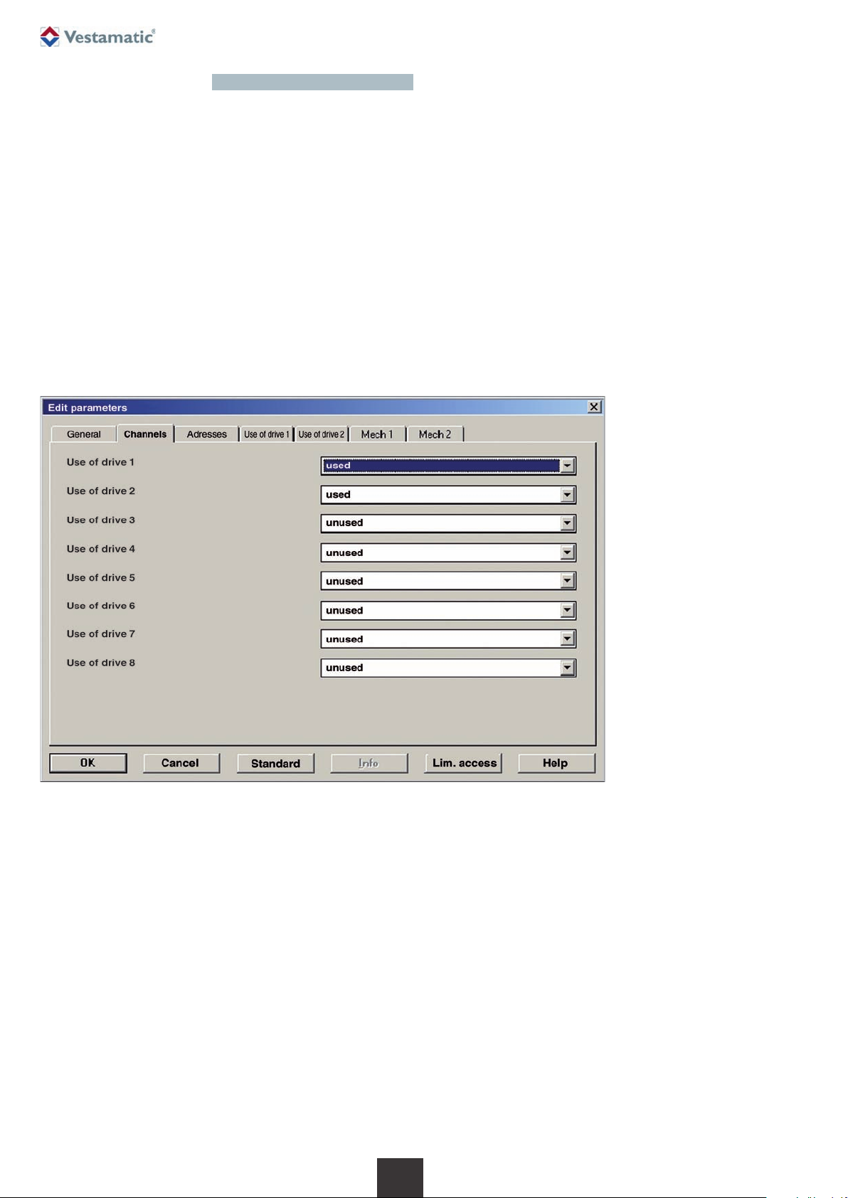
Fig. ETS interface
ETS2, two channels activated,
individual parametrisation,
automatic addressing.
ETS interface
The configuration of the ETS interface (communication objects and parameters) is based on the blind actuators already available on the market.
This ensures that the device can be parametrised and activated by the
project manager with a minimal period of adjustment.
The parameters are systematically arranged on tabs. In addition to general
parameters, which are collectively active for the actuator, the selection of
channels or drives to be used and their SMI addressing can be defined on
two other tabs. All other tabs, parameters and communication objects are
shown or masked out depending on the channels selected and settings
carried out. Depending on the default setting, all of the up to eight channels are set as “unused” so that initially only two general communication
objects (lock and safety) and no other elements are illustrated for the
channels. Other communication objects and parameters only appear for
the channels selected as “used”.
 Loading...