

Excellence
Sunshade Control
Installation and Operating Instructions

Safety precautions
·
Please note, that the
Vestamatic Excellence sunshade cont
rol requires an
operating voltage of 230 VW, 50 Hz. Therefore, the connection box may
only be installed and connected by a qualified professional electrician.
·
If work is performed on sunshade or roof windows, which are controlled by
the
Vestamatic Excell
ence
sunshade control, the operating voltage must be
turned off at the connection box.
·
The control was designed for correct use as described in the operating
instruc
tions. Any changes or modifications thereof are not permissible and
result in loss of al
l warranty claims.
·
Check the Excellence
sunshade control for signs of mechanical damage
immediately after unpacking. If there is any damage due to the shipping,
notify the supplier immediately.
Do not start up the control in case there is any damage!
·
If safe operation of control or sunshade can not be guaranteed, the
Excellence sunshade control must be turned off immediately and protected
against unintentional operation.
·
If
the
Excellence sunshade control is not connected to a rain or frost pro
-
tecto
rs, we recommend to set the control (depending on the sunshade
design) to manual operation at temperatures below +1 °C (32 °F) for safety
reasons. That way, automatic extending (e.g. at sunlight
) can be avoided.
·
Make sure to always replace used batteries
in the operator and display
element with batteries of the same type.
Caution! Risk of explosion, if incorrect battery types are used.
Dispose of used batteries only according to hazardous waste
regula
tions.
·
The use of plug-in power supplies, that are
not optionally delivered by the
Excellence
sunshade control manufacturer can cause malfunctions and/or
damage to the control and is thus not permissible.
·
Follow the installation and operating instructions carefully.
-
2 -

Contents
Safety precautions
p
age 2
Contents
page 3 – 4
Introduction
page 5
Installation
Installing the control unit
page 6 – 7
First steps
Start-up
page 8 – 9
Touch-screen calibration
page 10
Operation
page 11
Menu general
page 12
Measured values
page 13
Info
General
pa
ge 13
Touch-screen lock
page 14
Communication test
page 14
Status
page 15
Settings
General
page 16
Time
page 17
User settings
General
page 18
Wind
page 19
Sun
page 20
Temperature
page 21
Time
page 22
Rain
page 23
Run time
page 23
Re
verse time
page 24
-
3 -

Contents
Extended settings
General
page 24
Code
page 25
Test mode
page 26
Wind sensors
page 26
Expanded wind range
page 27
Wind velocity unit
page 27
Wind sensor type
page 28
Wind response delay
page 28
Sun sensors
page 29
Sun sensor assignment
page 29
External button direct/deadman
page 30
Rain priority
page 30
Rain motor 1
page 31
Rain motor 2
page 31
Continuous up command/run time
page 32
Continuous down command/run time page 32
Motor 2 roof win
dows
page 33
Language
page 33
Error and alarm messages
page 34 – 35
Maintenance and care
page 36
Technical data
page 37
Menu navigation
page 38
Adjustable values and times
page 39 – 40
Wiring diagrams
Connection of decentralized controls page 41
Direct connection of 2 drives
page 42
Connecting the operator element Excellence
via a 2-wire interface
page 43
Setting the rain sensor sensitivity
page 44
-
4 -

Introduction
Congratulations for buying the
Vestamatic Excellence sunshade control.
You
have purchased a high-quality product that features many practical functions
and is manufactured according to the highest quality standards.
Please take the time to read these operating instructions carefully prior to
start-up, in order to guarantee op
timum effectiveness and reliability.
The delivery extent of the
Vestamatic Excellence sunshade control includes the
following items:
1. Control unit, consisting of
– connection box
– operator and display element (touch-screen)
2. Wall mounting plate fo
r operator and display element
3. Mounting material
4. Display cleaning cloth
5. Four batteries (not applicable for 2-wire interface)
6. Installation and operating instructions
In the following, the term “control” is used for the entire system, consisting
of
connection box (sensor motor box) and operator and display element (touch
-
screen monitor).
-
5 -

Installation Installing the control unit
Please note, that the installation of the
Vestamatic Excellence sunshad
e
control may only be carried out by a qualified professional electrician.
If you have purchased a control with radio connection, avoid large metal
objects between control and operator and display element and adjacent to the
mounting location. Large metal
objects can impair the radio connection.
1. Turn off the operating voltage.
2. Remove the connection box cover and mount the housing with the four
holes in the housing corners. Mount the housing in such a way, that the
cable inlets are located on the low
er housing side. Do not mount the con
-
nec
tion box in a location exposed to direct sunlight.
3. Connect the power supply cables and external connections according to
the wiring diagram (see page 41).
Mount the control unit out of the range of people, children and animals.
All cables must be permanently wired.
Attention: Currently valid VDE-regulations must be observed when
connecting the device, in particular DIN VDE 0100/0700 as
well as the currently valid regulations of your local power
supplier and th
e accident prevention regulations.
4. The output is potential-free, which is important when triggering decen
-
tralized controls.
5. When directly connecting a motor (230 V~, 50 Hz), make sure to bridge
ter
minal C of the motor output with terminal L of
the mains connection.
-
6 -

Installing the control unit Installation
If you have purchased a control unit with two-wire interface, mount the
operator and display element as follows:
– Mount the wall bracket in the desir
ed location. The mounting location of the
operator and display element must not be exposed to direct sunlight.
– Remove the left cover from the battery compartment of the operator and
display element, by pulling it to the left and off the housing.
– Pierce
the circular openings prepared for the cable inlets on the housing
rear side.
– Connect the two-wire interface.
– Re-attach the battery compartment cover in its original position.
– Hang the operator and display element onto the wall bracket.
– Connect th
e voltage supply of the connection box.
Proceed as described in section “First steps”.
Ensure you have re-attached the cover!
If you have purchased a radio-controlled unit, perform the installation as follows:
– Turn on the connection box operating voltage.
– Remove the covers from the battery compartment of the operator and
display element, by pulling them to the side and off the housing.
– Insert the delivered batteries as indicated.
Proceed as described in section “First steps”.
Ensure you have re-attac
hed the cover!
If you have decided on the wall mounting, teach-in the operator and display ele
ment to the connection box by performing a ‘communication test’ (see page 14).
That way, you can find a suitable mounting location, that allows for trouble-free
communication between touch-screen and connection box.
The mounting location of the operator and display element must not be ex
posed to direct sunlight.
– Mount the wall bracket in the desired location.
– Re-attach the battery compartment cover in its o
riginal position.
– Hang the operator and display element onto the wall bracket.
Important: For test purposes, the system can be operated in the test mode
(see “Extended settings” on page 24).
-
7 -

First steps
Start-up
Please note, starting-up the control requires opening the connection box.
Therefore, start-up must be carried out only by a qualified professional electri
cian.
Systems with two-wire interface:
Ensure that the slide-switch, loca
ted in the terminal cut-out behind the left bat
tery compartment of the operator and display unit, is set in the upper position.
The slide switch in the connection box next to the radio module (for the exact
location, please see the wiring diagram) must al
so be set in the upper position.
Other configuration steps are not required.
Radio-controlled systems:
Ensure that the slide-switch, located in the terminal cut-out behind the left bat
tery compartment of the operator and display unit, is set in the lo
wer position.
The slide switch in the connection box next to the radio module (for the exact
location, please see the wiring diagram) must also be set in the lower position.
The operator and display element must be “taught-in” to the connection box as
foll
ows:
– Activate the operator and display element.
– Insert the batteries in the compartments of the operator and display
element or connect the plug-in power supply (available as special
accessory) to the operator and display element.
-
8 -
Start-up
First steps
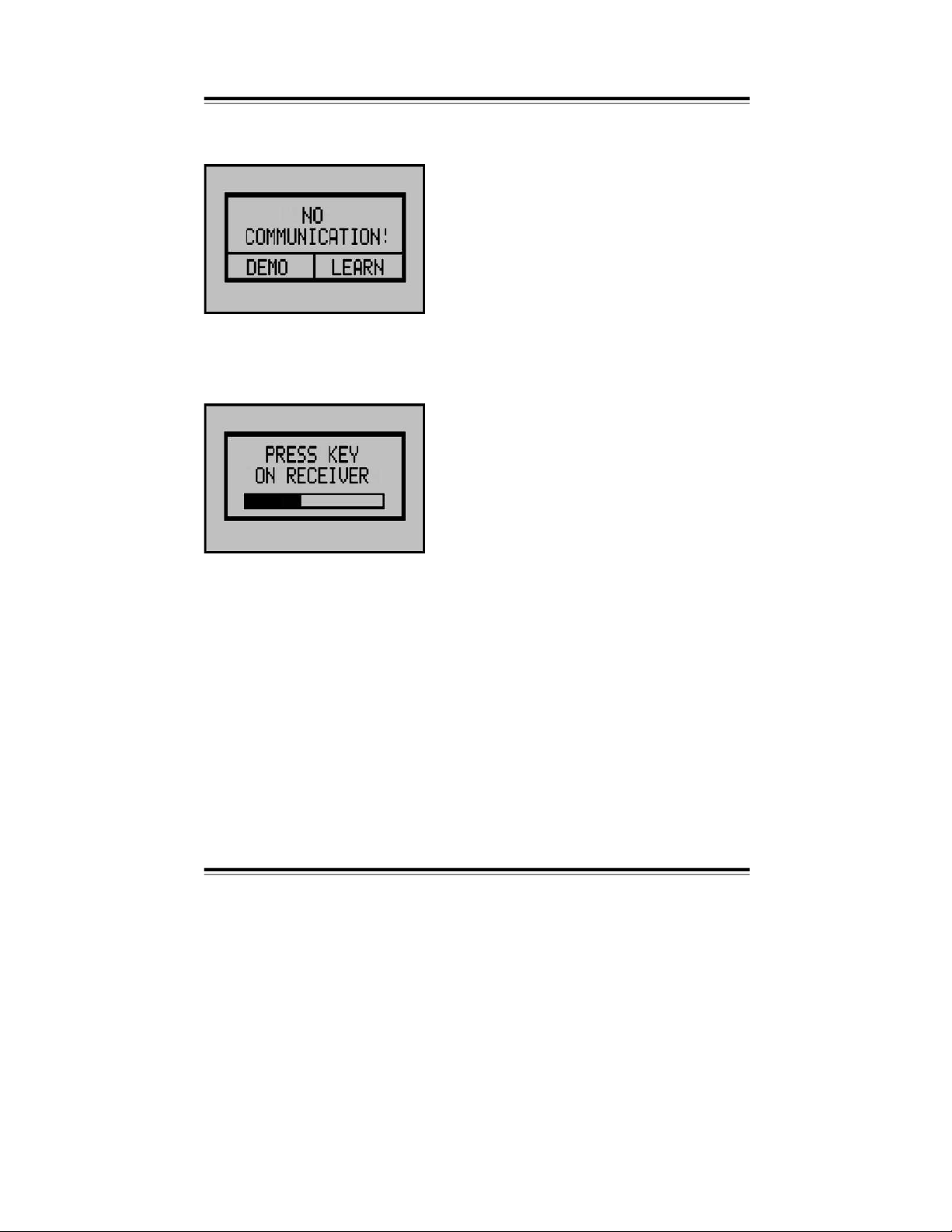
The following message will be displayed on the touch-screen of the operator
and display element.
Now, you can select between demo and
teach-in mode. In the demo mode, no radio
connectio
n between the operator and
display element and control unit can be
established. Therefore, control operations
or configuration steps cannot be per
formed. If the operator and display element
has not been “taught-in” with the con
nec
tion box, select the te
ach-in mode by
pressing the ‘TEACH-IN’-button.
After selecting the teach-in mode, the following message is displayed:
Make sure, the supply voltage for the con
nec
tion box is turned on. If it is not, turn on
the operating voltage and wait for at least
5 seconds. Then tap the ‘TEACH-IN’-but
-
ton of the connection box (see wiring dia
-
gram) with an
insulated
screwdriver. The
red LED next to the button will flash. If the
operator and display element recognizes
the connection box, the LED will stop flash
-
ing
and the touch-screen will display the
standard user interface. The system is now
ready-to-operate.
Taught-in operator and display elements can be deleted by pressing the
‘TEACH-IN’-button on the connection box for 5 seconds.
-
9 -
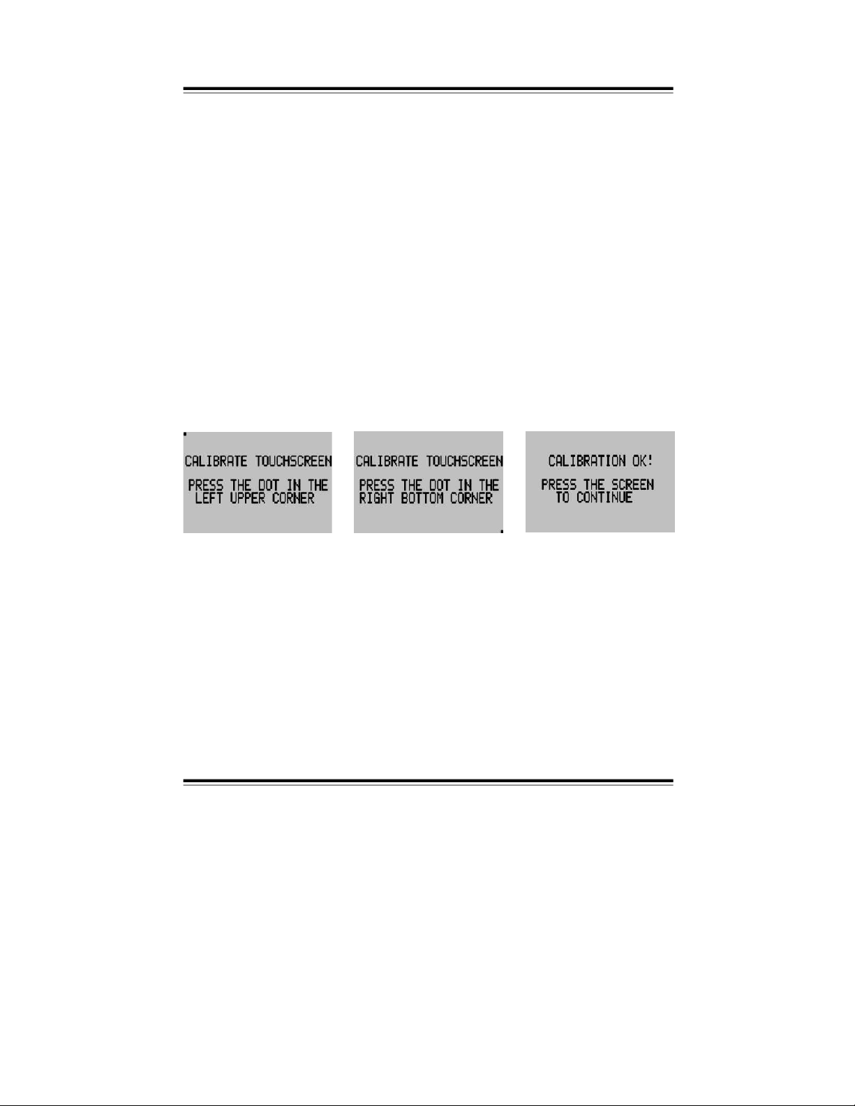
Touch-screen calib
ration
After long periods of operation, the touch-screen accuracy may deteriorate and
require re-calibration.
Activate the calibration function as follows:
1. Turn off the operating voltage by moving the slide-switch located behind
the left battery comp
artment (in the terminal cut-out) into the opposite
position.
2. Press the touch-screen and keep it pressed.
3. Turn the operating voltage back on, by moving the slide-switch back into its
original position.
4. Keep the touch-screen pressed for 3 seconds
until the operator and display
element is activated.
5. When the following screens are displayed, follow their instructions: First
press the dot in the upper left corner then press the dot in the lower right
corner. Then press the screen again at any posit
ion in order to return to
nor
mal operation.
-
10 -
Operation
Please bear in mind, that a touch-screen is a very sensitive component.
Pressing it too hard or with sharp-edged objects can cause irreparable
damage. Do not touch the touch-screen with poin
ted or sharp objects.
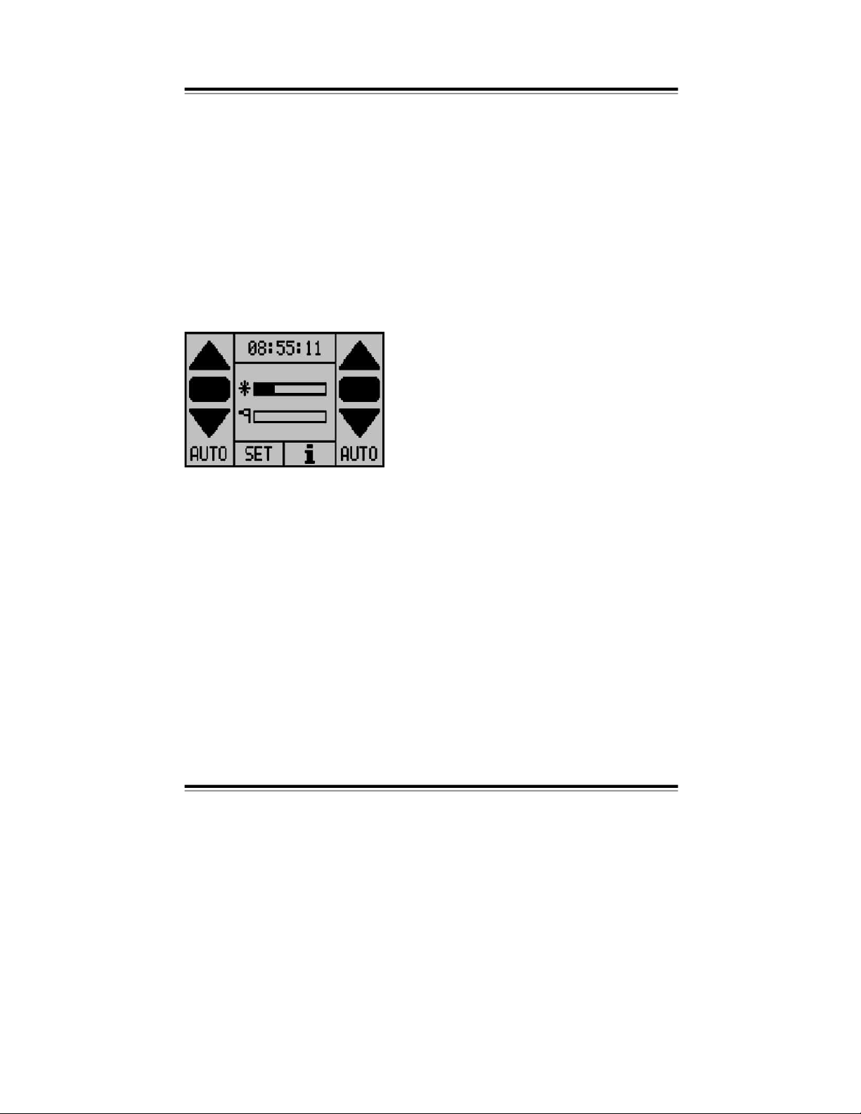
The operator and display element always displays the main menu first. From
this main menu, control functions can be executed and submenus can be
accessed.
The operator and display element is divided into several sections. The motor control buttons Up, Stop and Down for motor 1 (left) and motor 2 (right) are located on
the left-hand side. In addition, the motor control can either be set to the auto
matic
operating mode ‘AUTO’ or to the manual operating mode ‘MANUAL’. In the
manual mod
e, sun, temperature and time are disabled. Rain is set by the menu
option ‘Rain Priority’. If the motor operating mode is changed from manual to
automatic operation, the sunshade automatically moves into the correct position.
The status indica
tion in the display center shows the currently measured sen
-
sor values. Touching this area will indicate details and other measured values.
Pressing the Time button provides information on the current status of the
various control functions as well as the
current and last executed up/down
command of the control.
Pressing the
SET
button will open the ‘SET menu’, from which all settings can
be changed.
Pressing the ; button will indicate additional system data.
-
11 -
Menu General
The structure of most menus
is identical. If the amount of displayed data does
not all fit on the screen, a scroll bar will be indicated on the left. On this bar,
you can scroll to the information not shown on the screen. Four function keys
are located in the lower section of the scr
een. These functional keys can be
assigned to various functions. The functions used on the different screens are
described below:
Moves the scroll bar up.
Moves the scroll bar down.
Back to the previous menu.
Selection of motor 1 or 2. The large number
indicates the currently
selected motor.
Pressing this button will toggle between motor 1 and 2.
Battery-powered operator and display elements will automatically shut down,
after one minute of stand-by operation, in order to save battery life. Pushing
th
e touch-screen re-activates the operator and display element.
Settings can be entered in a pop-up menu. If settings need to be entered sepa
-
rately for each motor, the respective motor can be selected at the top of the pop
up window. Settings, that were selected via a scroll bar, can be entered by means
of the plus and minus buttons or by pressing the status bar. The minimum value is
always displayed on the left, the maximum value is displayed on the right.
-
12 -
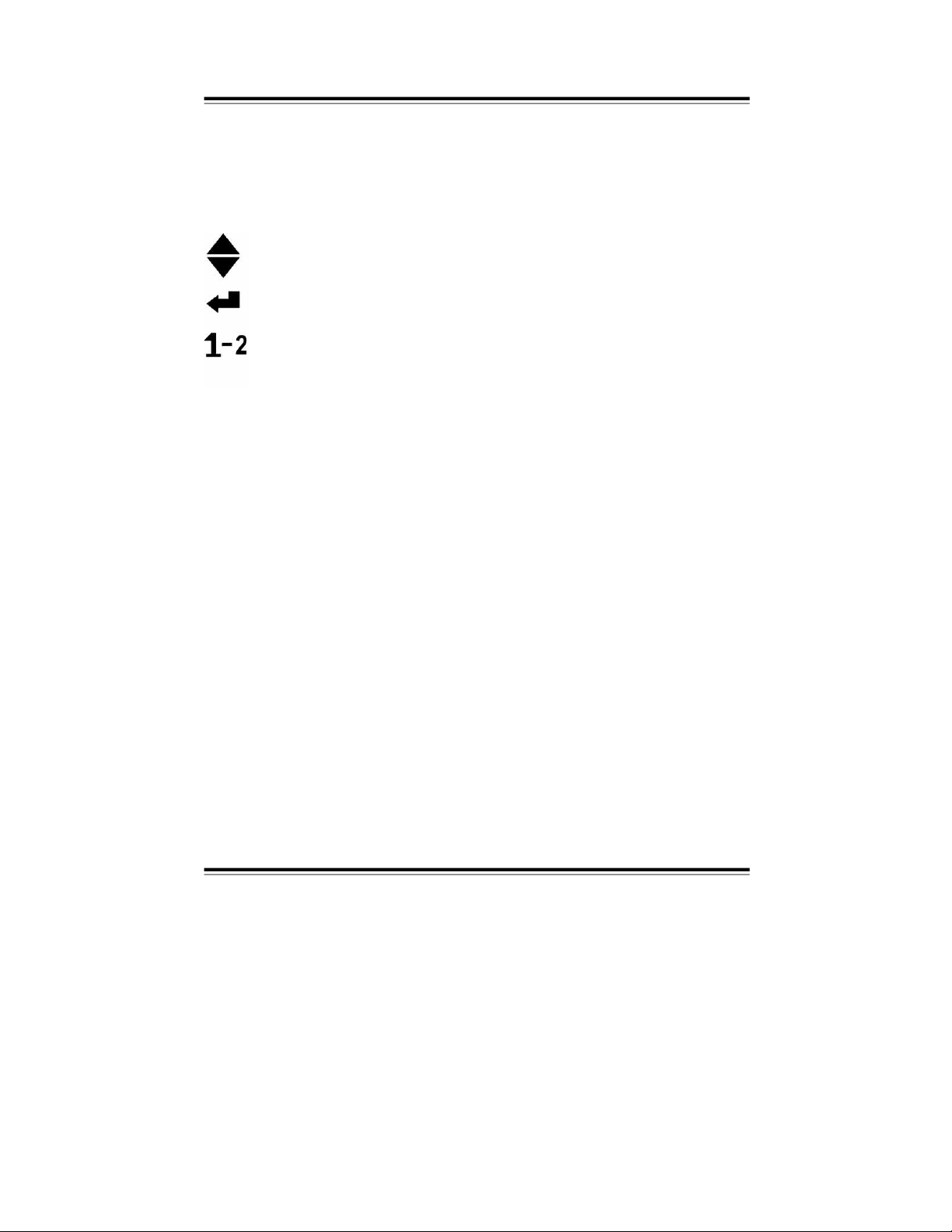
Measured values
This menu indi
cates the measured values. The scroll bar on the right indicates,
when more values are available than fit on the screen.
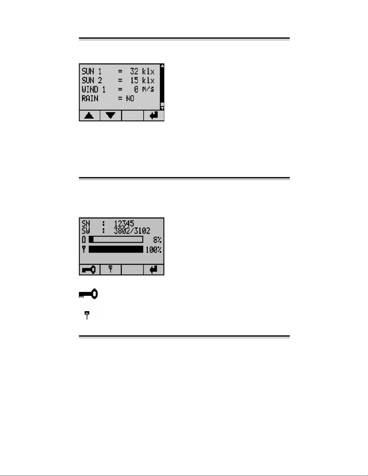
General Info
The info screen shows the serial-
number and software-version of the operator
and display element as well as the control unit. Furthermore, this screen pro
vides a status indicator showing the battery charge state and a display indicat
ing the communication quality of the last data tran
smitted.
In this menu, the touch screen remains locked until the correct code
(8192) is entered.
This is the menu for the communication test.
-
13 -
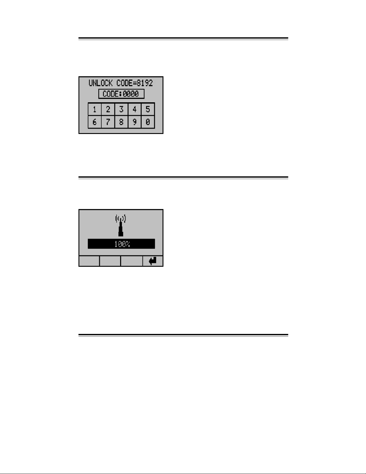
Info Touch-screen lock
On this screen,
the touch-screen is locked. The locking function is particularly
useful when cleaning the touch-screen. As soon as the correct code is entered
or the operator and display element shuts down, the touch-screen is ready for
operation again. As a reminder, the
code is displayed at the top of the screen.
Info Communication test
In this menu, you can test the communication quality, which is very useful when
establishing a radio connection. With th
is function, you can determine the opti
-
mum mounting location for the operator and display element.
-
14 -

Status
Pressing the clock symbol in the main menu displays the status menu. This
menu indicates the motor status and all other functions. Th
e symbols in the
columns on the left indicate the function. The symbols next to each function
represent their respective status.
Status display:
The status of the sunshade or function is Position Up.
If the motor was triggered to move the sunshade into this direction, this arrow is flashing.
The status of the sunshade or function is Position Down.
If the motor was triggered to move the sunshade into this direction, this arrow is flashing.
This symbol indicates, that the motor is cu
rrently not activated. The sunshade is
neither moving up or down.
This function is inactive.
This function is deactivated.
This function has been switched to manual operation.
This symbol will only be indicated in combination with the symbols : or u and signals,
that a delay is activated. The other symbol shows the function status after the delay
has elapsed.
Functions:
Motor status
Sun function
Temperature function
Wind function
Rain function
Frost
Time function
-
15 -

Settings General
With this menu, you can set the contrast of the operator and di
splay element
and access other settings. Touch the bar to set the contrast. On the very left of
the bar, the contrast amounts to 0 %, on the very right it amounts to 100 %.
The changed settings will be immediately displayed.
If you have purcha
sed a device with illuminated display, the functionality of the
illumination can be set as follows:
The illumination is permanently turned off.
When pushing the touch-screen panel, the illumination is turned on
and will expire 3 seconds after the control
panel has been pushed.
When using a power outlet or a control unit, equipped with a 2-wire
interface, the illumination is permanently turned on.
Touching this symbol will open the menu ‘Time’, in which the current
time can be displayed.
Touching this symbo
l will open the menu ‘User Settings.’
Touching this symbol will open the menu ‘Extended User Settings’.
Incorrect settings in this menu can cause damage to the sunshade!
Back to the previous menu.
-
16 -

Time
Settings
On this screen, you can set the time. The time in small digits indicates the
current time. The time in large digits is the new time, which can be changed by
pressing the hours and the minutes. A pop-up menu will be displayed
, in which
hours or minutes can be changed by pressing the +/- buttons or the status bar.
Changes on the time must be acknowledged with the OK button. Starting the
clock with the changed time requires to push the OK button again. That way,
the time can be
set right to the second. After the correct time has been set, the
pop-up menu can be exited by pressing the ,-
button.
-
17 -

User settings General
In this menu, you ca
n change all user settings, such as wind, temperature, time,
rain, run time and reverse time. Functions with only one setting can be directly
changed. Other settings must be changed in a submenu. All settings are changed
in a pop-up menu. With the arrows,
you can access data currently not displayed
on the screen.
Wind settings
Sun settings
Temperature settings
Time settings
Rain settings
Run time
Reverse time
-
18 -

Wind User settings
The set wind velocity threshold value must be smaller than the maximum wind
value that a sunshade can withstand. If the wind velocity attains or exceeds
the set value, the wind functions issues an Up command.
The wind reset delay can be set to the desired value. The wind velocity must
be below this threshold value for the duration
of the wind reset delay, before a
Down command can be issued.
-
19 -

User settings Sun
The sun-dependent control can be turned on or off.
In order for the sunshade
to extend automatically, the sun intensity must be
higher than the sun response value for the duration of the preset sun response
delay.
If both the sun- and the temperature-dependent controls are activated, the
sunshade will automatically extend only, if
the temperature set on the room
thermostat is exceeded.
If the sun intensity falls below the Up threshold value over the entire duration
of the reset delay, the sunshade automatically retracts after the reset delay
time has elapsed.
-
20 -

Temperature
User settings
The temperature functions responds to the values entered in the thermostat. If
the temperature is too low, the contact is closed and the sunshade will retract
after the temperature reset delay h
as elapsed.
If both the sun- and the temperature-dependent controls are activated, the
tem
perature function will only issue an Up command when the temperature is
too low. Other sunshade functions are controlled by the sun function.
-
21 -

User settings Time
With the time function, the sunshade can be stopped in Up or Down position for
a certain period of time, even if the automatic mode was previously selected.
In order
to change the time, press the hour and minute to adjust the time to be
changed. This command remains activated from start to stop time. If start and
stop time are identical, a run time command is issued. The time command can
be - activated and + deactivat
ed. On the screen-shot below, the Up com
mand
is activated and a continuous retract command is issued for the time period
between 01:00 and 02:00.
Down function and manual operation are deactivated.
Example time function:
Your sunshade shall extend at 08:00 in the morning. Until 16:00 in the afternoon
it shall not execute any sun- or temperature-dependent commands. After 16:00,
the sunshade shall issue a sun-dependent extend or retract command.
In this case, set the time function as follows:
T
ime-dependent control up: deactivated
Time-dependent control down: activated
Start: 0 8:0 0 Stop: 0 8:0
5
Manual mode:
activated
Start: 0 8:0 0 Stop: 1 6:0
0
-
22 -

Rain User settings
For
the rain function, only the reset delay can be set. If rain is detected, the
sunshade will retract immediately. If no rain signal is applied during the entire
duration of the reset delay, the sunshade extends, after the delay time has
elapsed, provided that the control is in automatic mode and all pre-conditions for
automatic extending are fulfilled.
During start-up, the sensitivity of the rain sensor can be set by means of a wire
jumper (refer to wiring diagram, see page 44).
Run time
User settings
The run time is the time the sunshade requires to move from the Up into the
Down position. The run time for an Up command always amounts to 180
seconds.
-
23 -

User settings
Reverse time
The reverse time is executed after a temperature- or sun-dependent up/down
-
command and after a manual up/down command.
Extended settings
General
The extended settings are used for the configuration of the system, e.g. to set
sensors and system functions.
Note: Incorrect settings can cause damage or even destruction of the
system!
The settings in this menu apply for both motors!
-
24 -

Code Extended settings
Since incorrect settings can cause damage to the system, a code protects the
menu from unintentional modifications.
CODE = 2389
After the correct code is entered, the
next menu will be displayed.
-
25 -

Extended settings Test mode
In the test mode, all delay times are running 5 times faster than during normal
operation. The wind sensor monitoring respon
ds after 90 seconds. The test
mode can be turned ON and OFF. The test mode remains activated until it is
deactivated by pressing ‘OFF’.
Continuous operation of the control in the test mode is not permissible.
Extended settings
Wind sensors
In this menu, the number (0 – 2) of wind sensors connected to the control unit
can be set.
-
26 -

Expanded wind range Extended settings
In this menu, the user can set the wind v
elocity range. The standard setting is
10–40 km/h. If the expanded wind range was selected by pressing ‘ON’, the
wind velocity range is 10–100 km/h.
Wind velocity unit Extended settings
This option allows for setting the wind velocity in km/h or m/s.
-
27 -

Extended settings Wind sensor type
This option allows for setting the type of wind sensor connected to the control
unit. The available wind sensor type option
s are standard (unheated) and
special (heated).
Extended settings Wind response delay
In this menu, the wind response delay can be set. The wind response delay is
the time period, the wind velocity must exceed
the threshold before the
sunshade retracts. This time can be set between 0–10 seconds. Please note,
the sunshade may respond significantly later, if the delay time is increased.
-
28 -

Sun sensors Extende
d settings
In this menu, the number (0 – 2) of sun sensors connected to the control unit
can be set.
Sun sensor assignment Extended settings
In this menu, the sun sensors can be assigned.
A: Both motors respond to the sensor, that measures the highest value.
B: Sensor 1 is assigned to motor 1 and sensor 2 is assigned to motor 2.
-
29 -

Extended settings External button direct/deadman
In this menu, the functionality of the operating buttons of the
standard display,
and the up/down buttons (option) connected to the control unit can be set.
Direct: By pressing the Up or Down button, the run time command is directly
activated.
Deadman: The Up or Down button must be pressed for 2 seconds before the
ru
n time command is activated. Commands with a duration less than
2 seconds, will be executed for as long as the button is pressed.
Extended settings Rain priority
In this menu, the rain and frost func
tions can also be activated in the manual
mode.
OFF: Manual extending in manual mode is also possible at rain and frost.
ON: Manual extending at rain and frost is not possible, even in manual opera
-
tion.
-
30 -

Rain motor 1
Extended settings
In this menu, the rain function for motor 1 can be activated.
OFF: Motor 1 will not automatically retract the sunshade at rain or frost.
ON: Motor 1 will automatically retract the sunshade at rain and frost depend
-
ing on
the ‘rain priority’ setting.
Rain motor 2 Extended settings
In this menu, the rain function for motor 2 can be activated.
OFF: Motor 2 will not automatically retract the sunshade at rain or frost.
ON: Motor 2 will automatically retract the sunshade at rain and frost depend
-
ing on the ‘rain priority’ setting.
-
31 -

Extended settings Continuous up command/run time
In this menu, the function of the external Up outputs can be configured.
CONTINUOUS: An input signal continuously activates the motor for the dura
tion of the applied signal and even beyond the duration of the
motor run time.
RUN TIME:
An input signal activates the motor for the duration of the set
run time.
Exte
nded settings Continuous down command/run time
In this menu, the function of the external Down outputs can be configured.
CONTINUOUS: An input signal continuously activates the motor for the dura
tion of the applied signal and even beyond the duration o
f the
motor run time.
RUN TIME:
An input signal activates the motor for the duration of the set
run time.
-
32 -

Motor 2 roof window Extended settings
In this menu, the functionality of motor 2 can be configured.
NO: Mot
or 2 runs in the normal operation mode.
YES: The functionality of the Up and Down button on the operator and display
element for motor 2 will be switched, i.e. pressing the Up button will
extend (open) the roof window – pressing the Down button will retrac
t
(close) the roof window.
Language Extended settings
In this menu, the language for the operator and display element can be set.
English, Dutch, German and French are the available languages.
-
33 -

Error and alarm messages
Error and alarm messages are displayed if an error occurs. Press OK to
acknowledge the message. After activating the operator and display element,
the message will be displayed again. After elimination of the error,
the error
message will automatically disappear.
Possible error messages:
Sun sensor 1 is defective, not connected or
short-circuited.
Sun sensor 2 is defective, not connected or
short-circuited.
Wind sensor 1 has not sent any sign
als for
48 hours. Rotate the vane anemometer to
check the sensor.
-
34 -

Error and alarm messages
Wind sensor 2 has not sent any signals for
48 hours. Rotate the vane anemometer to
check the sensor.
Wind sensor 1 cannot be detected. Check
the wiring. As long as the wind sensor is not
detected, the Up command remains
activated.
Wind sensor 2 cannot be detected. Check
the wiring. As long as the wind sensor is
not detected, the Up command remains
activated.
The batteries are almost c
ompletely discharged.
Replace the batteries and only use batteries of the
same type. If the battery charging capacity drops below
10 %, the operator and display element shows maxi
mum contrast in order to ensure optimum readability.
If you have purchased
a unit with two-wire interface, the
position of the slide switch on connection box and
operator unit must be verified (see chapter, “Start-up /
First steps”).
-
35 -

Maintenance and care
Severely soiled operator and display elements can be cleaned with a moist
cloth. Do not use solvent-based or aggressive cleaning agents. Lock the touch
screen before you start cleaning, as previously described in the operating
instructions, to prevent undesired system operation.
Exchange empty batteries to prevent possible leaks (see instructions).
-
36 -

Technical data
Control unit:
Power supply:
230 V~, 50 Hz
Rated power:
6 W
Fuses:
0.1 A/T (control)
6.3 A/T (motor circuits)
Output:
potential-free
Maximum load:
4
A, 230 V~, cos
f >
0.8
Switching time:
5 – 180 seconds
Operating temperature:
-
20 to +50 °C
Storage temperature:
-
20 to +70 °C
Relative air humidity:
max. 80 %
IP class:
IP 54
Weight:
approx. 850 g
Dimensions L × W × H:
190 × 155 × 87 mm
Radio specifications:
Frequency:
433.92 MHz
Modulation:
FSK
Range:
2
5 m indoor (depending on the ambient conditions)
Wire length 2-wire:
max. 50 m
Operator and display element:
Power supply:
Battery:
4 × 1.5 VDC (4*AA batteries)
DC-adapter:
9 VDC adapter (use only the Excellence adapter!)
2-
wire:
voltage supply from the control unit
Operating temperature:
0 to +40 °C
Storage temperature:
-
20 to +60 °C
Relative air humidity:
max. 80 %
IP class:
IPx0
Weight:
approx. 250 g
Dimensions L × W × H:
160 × 105 × 35 mm (depends on the housing)
Battery life:
> 1 year (normal use)
Radio specifications:
Frequency:
433.92 MHz
Modulation:
FSK
Range:
25 m indoor (depending on the ambient conditions)
Wire length 2-wire:
max. 50 m
The operator and display element can contain pollutant batteries.
The end user is obliged to recycle the battery according to Regulation 91/157/EWG.
-
37 -

Menu navigation
Input: 2389
-
38 -

Adjustable values and times
The control unit is delivered with the following preset default parameters.
Please have the values adjusted to your system during start-up.
SET menu:
Funct
ion
Default setting
Your setting
Contrast
0 –
100 %
50 %
Background illumination
OFF / 3 sec. / ON
3 sec.
User settings:
Function
Default setting
Your setting
motor 1
motor 2
Wind threshold value
for expanded wind range
10 –
40 km/h
10 –
100 km/h
30 km/h
Wind reset delay
2 –
20 min.
16 min.
Sun-dependent control
ON / OFF
ON
Sun response value
Extend
1 –
60 kLux
15 kLux
Sun response delay
10 –
240 sec.
75 sec.
Sun response value
Retract
1 –
60 kLux
13 kLux
Sun reset delay
02:00 –
40:00 min.
16:00 min.
Temperature-dependent
control
ON / OFF
ON
Temperature reset delay
01:00 –
15:00 min.
05:00 min.
Time control Up
00:00 – 23:59
ON / OFF
00:00 – 00.00
OFF
Time control Down
00:00 – 23:59
ON / OFF
00:00 – 00.00
OFF
Time control automatic lock
00:00 – 23:59
ON / OFF
00:00 – 00.00
OFF
Rain reset delay
1 –
15 min.
2 min.
Motor run time Down
5 –
180 sec.
90 sec.
Reverse pulse
0 –
2.0 sec.
0 sec.
-
39 -

Adjustable values and times
Extended settings:
Functio
n
Setting options
Default setting
Your setting
Test mode
ON / OFF
OFF
Wind meter
0 / 1 / 2
1
Expanded wind range
ON / OFF
OFF
Wind velocity unit
km/h / m/s
km/h
Wind meter type
Standard / heated
Standard
Wind response delay
0 –
10 sec.
0 s
ec.
Sun sensors
1 / 2
1
Sensor assignment
(applicable only for systems
with 2 sun sensors)
A / B B
Locking after 2 seconds
Direct / deadman
Direct
Rain priority
ON / OFF
ON
Rain-dependent control
motor circuit 1
ON / OFF
ON
Rain-dependent control
motor circuit 2
ON / OFF
ON
External Up command
Cont. / run time
Run time
External Down command
Cont. / run time
Run time
Motor circuit 2 for roof window
YES / NO
NO
Language
English / Dutch /
German / French
German
-
40 -

Connection of decent
ralized controls Wiring diagram
-
41 -

Wiring diagram Direct connection of two drives
-
42 -

Connection of the operator and display element with two-wire interface
-
43 -

Setting the rain sensor sensitivity
-
44 -
 Loading...