

Page 1
1 2
Quick Installation Guide
Safety Information
The following safety symbols are used in this manual for user's safety. Read this manual
carefully and follow all instructions to avoid property damage, fire, explosion, personal
injury, or death.
- Do not store or use gasoline or other ammable vapors and liquids in the vicinity
of this or any other appliance.
- What to do if you smell gas
• Do not try to light any appliance.
• Do not touch any electrical switch; do not use any phone in your building.
• Immediately call your gas supplier from a neighbor’s phone. Follow the gas
supplier’s instructions.
• If you cannot reach your gas supplier, call the re department.
- Installation and service must be performed by a licensed professional.
- Follow all local codes and/or the most recent edition of the National Fuel
Gas Code (ANSI Z223.1/NFPA 54) in the USA, or the Natural Gas and Propane
Installation Code in Canada (CAN/CGA B149.1).
Before Installation
Choosing an Installation Location
When considering a location for installation, read “Installing the Boiler ” in the Installation Manual.
Checking the Clearances
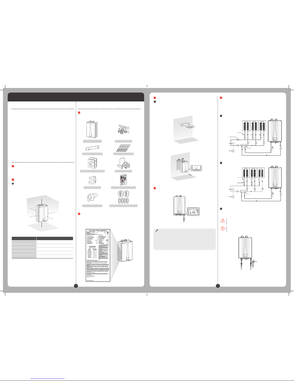
Clearances
The boiler should be installed in an area that allows for service and maintenance access
to utility connections, piping, filters, and traps. Ensure the following clearances are
maintained:
Side
Side
Front
Back
Top
Bottom
Clearance From Wall Mounting
Top 12 inches (305 mm) min.
Back 0.6 inches (15 mm) min.
Front 6 inches (152 mm) min.
Sides 3 inches (76 mm) min.
Bottom 12 inches (300 mm) min.
Installation
Opening the Box
The following items are included with the boiler . Check each of the following items
before installation.
VST boiler Spare parts
Wall mounting bracket Tapping screws & anchors
Installation and User manual Gas conversion kit
Vent clip Quick installation manual
Pressure reilef valve 2” Vent termination cap & Wall flange
Checking the Rating Plate
Before the installation, check the rating plate located on the side of the boiler to ensure
that the boiler matches the gas type, gas pressure, water pressure, and electrical supply
available in the installation location. If the boiler does not match each of these ratings,
do not install the boiler . If the gas conversion is required, the included gas conversion
kit must be used.
VRC۱٤۰-
۱٤۰,۰۰۰
۱۹۹,۰۰۰ ۱۹,۹۰۰
۱۹,۹۰۰
Natural Gas
۱۰٫٥
۳٫٥
۰٫٥۹- ~۰٫۰۱
۰.
Mounting the Boiler
Mounting to the wall
To mount the boiler to the wall:
1
Check that the wall is level and can support the weight of the boiler .
2
Affix the mounting bracket securely to the wall.
3
Align the grooves on the back of the boiler with the tongues on the mounting
bracket and hang the boiler from the bracket.
Connecting the Gas Supply
1
Connect the gas supply line.
2
Check for gas leaks at all joints.
Notice
• Tighten the boiler connection valves with care to avoid damage.
• Apply gas leak detection solution to all gas fittings.
• The minimum internal diameter required for any appliance connector is ¾ ”.
• When using flexible gas lines, ensure that the pipe’s inner diameter and connector is
sufficient to supply the required BTUs. Also, ensure that the flexible line has no crimps
or tight bends in it, as this will restrict gas flow.
• To facilitate any future maintenance or service, the installation of a union on the gas
supply line close to the boiler is recommended.
Example of System Applications
Refer to the following examples to properly implement a system for space heating.
These example are provided to suggest basic guidelines when you install the boiler
system. However, the actual installation may vary depending on the circumstances,
local building codes, or state regulations. Check the local building codes and state
regulations thoroughly before installation, and comply with them fully.
Zone System with Zone Valves
Zone Valve
Zone 1 Zone 2 Zone 3
System pump
Air Separator
Expansion tank
Not exceed Max.12 in
Zone System with Circulators
Check Valve
Zone 1 Zone 2 Zone 3
System pump
Air Separator
Expansion tank
Not exceed Max.12 in
Pressure Relief Valve
This boiler comes with an ASME-approved pressure relief valve to install space heating.
To complete the installation of the boiler, you must install an approved 3/4”, maximum
30 PSI (for space heating).
Warning
Improper installation of the pressure relief valve may result in property damage,
personal injury, or death. Follow all instructions and guidelines wllen installing the
pressure relief valve. Only a licensed professional should install the valve.
Caution
Install the pressure relief valve as close to the boiler as possible. No other valve
should be installed between the pressure relief valve and boiler.
Pressure rilief valve
Space heating return Space heating supply
If the pressure relief valve discharges hot water periodically, thermal expansion may
occur due to an expansion tank problem or small expansion tank size. Do not plug the
pressure relief valve.
VRC-80, 100, 120, 140
Ver. 1.1
Page 2
3 4
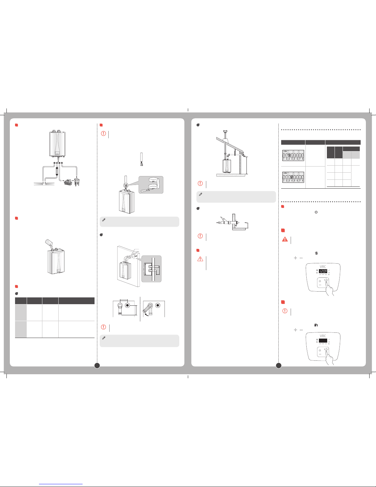
Connecting the Condensate Drain
External drain
Direct to
an external drain
To a drain via
a neutralizer
To a laundry tub
To a laundry tub via
a condensate pump
(a) From the boiler directly into an external drain.
(b) From the boiler , through a neutralizing agent, and then into an external drain.
(c) From the boiler into a condensate pump, and then into a laundry tub.
(d) From the boiler into a laundry tub.
Condensate Trap
Before operating the boiler , fill the condensate trap with water through the flue
connector. The boiler may be severely damaged unless filled with water prior to
operation. Pour 0.1 gallon (400 ml) of water into the exhaust duct. Deflate air sufficiently
or equip the air vent with an outlet pipe prior to filling the condensate trap with water
(there must be no air inside the heat exchanger).
Installing a Vent
Vent Lengt
Vent Size
Maximum
Length
Maximum #
of Elbows
Equivalent Lengths
2" 60' (18 m) 6
Reduce the maximum vent length
accordingly for each elbow used:
• Each 90° elbow equates to 8 linear
feet (2.4 m) of vent
• Each 45° elbow equates to 4 linear
feet (1.2 m) of vent
3" 150' (45 m) 8
Reduce the maximum vent length
accordingly for each elbow used:
• Each 90° elbow equates to 5 linear
feet (1.5 m) of vent
• Each 45° elbow equates to 3 linear
feet (0.9 m) of vent
Connecting the Vent Clip
Caution
To connect the exhaust vent firmly, must use the vent clip included with boiler .
To connect the vent clip:
1
Connect the vent clip to the exhaust vent.
2
Connect the exhaust vent and the vent clip to the flue connector.
Notice
Tighten the screws and fix the vent clip.
Two-pipe sidewall venting
Internal view
Intake air
Exhaust gas
10" min.
External view
12" (300 mm) min.
Intake air
Less than 45°
Exhaust Gas
12" (300 mm) min.
Caution
• Maintain 12" (300 mm) min. (18" (450 mm) min. for Canada) clearance above
highest-anticipated snow level. Maximum of 24" (600 mm) above roof.
• Install a bird screen at the end of the intake air pipe and exhaust pipe.
Notice
It is recommended to install the intake air vent terminal as far from the exhaust gas vent
terminal as possible.
Non-concentric sidewall venting
12" (300 mm) min.
10" (254 mm) min.
Caution
• Maintain 12" (300 mm) min. (18" (450 mm) min. for Canada) clearance above
highest-anticipated snow level. Maximum of 24" (600 mm) above roof.
• Install a bird screen at the end of the intake air pipe and exhaust pipe.
Notice
Air is drawn from a different location at a minimum of 12" (300mm) from the exhaust
termination. Try to minimize the length of the intake air pipe with this venting.
Concentric sidewall venting
Combustion air
Vent
Combustion air
Maintain 12"
(300 mm) min.
Vent
1" (25 mm) min.
Caution
Maintain 12" (300 mm) min. (18" (450 mm) min. for Canada) clearance above
highest-anticipated snow level. Maximum of 24" (600 mm) above roof.
Connecting the Power Supply
Warning
Improperly connecting the power supply can result in electrical shock and
electrocution. Follow all applicable electrical codes of the local authority having
jurisdiction. In the absence of such requirements, follow the latest edition of the
National Electrical Code (NFPA 70) in the USA or the latest edition of CSA C22.1
Canadian Electrical Code Part 1 in Canada. Connecting the power supply should
be performed only by a licensed professional.
When connecting the power supply, follow these guidelines:
• Do not connect the electric supply until all plumbing and gas piping is complete and
the boiler has been filled with water.
• Do not connect the boiler to a 220-240V AC power supply. Doing so will damage the
boiler and void the warranty.
• All boiler s come with a factory-installed, 3-pronged (grounded) plug. The boiler can
be plugged into any grounded electrical outlet nearby, as it requires only 2-4 Amps.
It is not necessary to run a dedicated electrical line to the boiler .
• If local codes require the boiler to be wired directly, remove and discard the factory-
installed plug. Install a power switch between the breaker and the boiler to facilitate
end-user maintenance and servicing. Connect the boiler to a 110-120V AC at 60 Hz
with a maximum of 5A rating electrical supply.
• The boiler must be electrically grounded. If using the power plug, ensure that the
electrical outlet you connect the boiler to is properly grounded. If wiring the boiler
directly to a power supply, do not attach the ground wire to either the gas or the
water piping as plastic pipe or dielectric unions may prevent proper grounding.
• We recommend using a surge protector to protect the boiler from power surges.
• If there is a power failure in cold weather areas, the freeze prevention system in the
boiler will not operate and may result in freezing of the heat exchanger. In cold
weather areas where power failures are common, you must completely drain the
boiler to prevent damage if the power is expected to be off for any extended period
of time. A battery back-up (available at most computer retailers) may be used to
supply hot water during periods of power outages. Damage caused by freezing is
not covered under warranty.
Setting the Long Flue
Set the DIP switch appropriately, depending on the installation environment.
Switch Function
Long flue Length 1
DIP
S/W
#3
DIP
S/W
#4
FLUE LENGTH
2”
PVC
3”
PVC
OFF OFF
Up to
15’
Up to
150’
OFF ON
Up to
30’
N/AON OFF
Up to
45’
ON ON
Up to
60’
Long flue Length 2
Operating the Boiler
Turning the Boiler On or Off
To turn the boiler on or off, press the button.
When the boiler is on, the water temperature which has been set recently will appear
on the digital display.
Setting the Space Heating Temperature.
Danger
If your household includes children, or elderly or disabled individuals, consider
using a lower temperature setting.
To set the space heating water temperature.
1
Press the MODE button until the icon turns on.
2
Press the or buttons until the desired temperature appears on the digital
display.
Setting the DHW Temperature
Caution
Water above 120°F (50°C) can cause instant scalding, severe burns, or death.
To adjust the water temperature:
1
Press the Mode button until the icon turns on.
2
Press the or buttons until the desired temperature appears on the display.
 Loading...