

Page 1
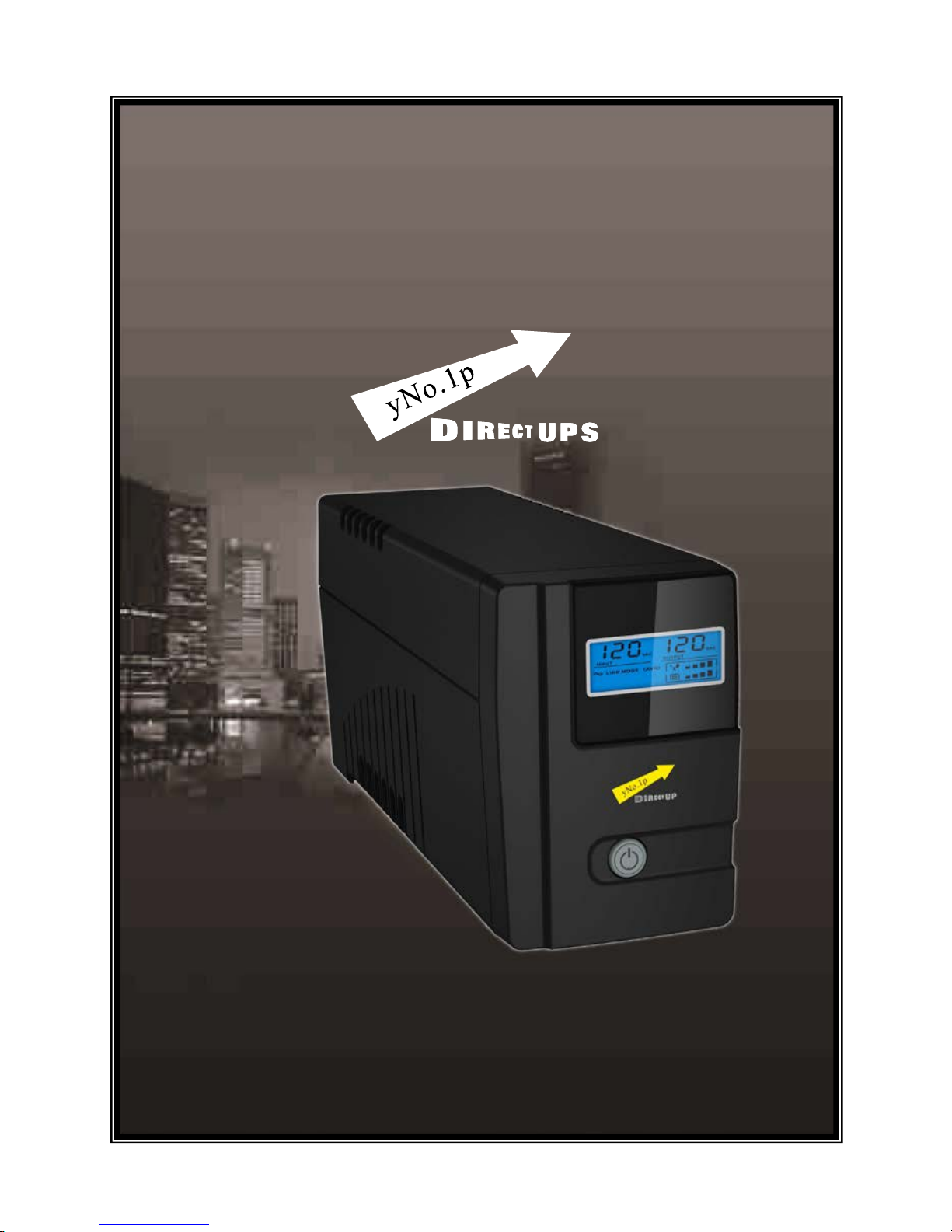
Vesta Pro 600 / 800 VAC
Uninterruptible Power System
USER MANUAL
USER MANUAL
Page 2

Page 3

IMPORTANT SAFETY INSTRUCTIONS
SAVE THESE INSTRUCTIONS –This manual
contains important in structions for models
Vesta Pro 600/800VAC that should be
followed during installation and
maintenance of the UPS and batteries.
Safety – CAUTION!
This UPS utilizes voltages that may be hazardous. Do not attempt to
disassemble the unit. The unit contains no user serviceable parts.
Only factory service personnel may perform repairs.
Internal battery voltage is 12Vdc. Sealed, lead-acid, 6 cells battery.
Connection to any other type of receptacle other than a two-pole,
three-wire grounding receptacle may result i n s shock hazard as well
as violate local electrical codes.
In the event of an emergency, turn the power switch to the “off”
position– on and disconnect the power cord form the AC power
supply to properly disable the UPS
Do not allow any liquids or any foreign object to enter the UPS. Do
not place beverages or any other liquid-containing vessels on or near
the unit.
This unit intended for installation in a controlled environment
(temperature controlled, indoor area free of conductive contaminants).
Avoid installing t he UPS in locations where there is standing or
running water, or excessive humidity.
Do not plug the UPS input into its own output.
Do not attach a po wer strip or surge suppressor to the UPS.
Do not attach no n-computer-related items, such as medical
equipment, life-support equipment, microwave ovens, or vacuum
cleaners to UPS
To reduce the risk of overheating the UPS, do not cover the UPS’
cooling vents and avoid exposing the unit to direct sunlight or
installing the unit near heat emitting appliances such as space heaters
or furnaces.
Page 4

Unplug the UPS p rior to cleaning and do not use liquid or spray
detergent.
Do not dispose of battery or batteries in a fire. The battery may
explode.
Do not open or mutilate the battery or batteries. Released
electrolyte is harmful to the skin and eyes. It may be toxic.
A battery can present a risk of electrical shock and high short circuit
current. The foll ow ing pr ec a utio ns sh ould b e o bs er ved w hen w orki ng
on batteries :
1) Remove watches, rings, or other metal objects from the hand.
2) Use tools with insulated handles.
3) Wear rubber gloves and boots.
4) Do not lay tools or metal parts on the top of batteries.
5) Disconnect char ging source pri or to connecting or di sconnecting
batteries terminal.
Servicing of batteries should be performed or supervised by personnel
knowledgeable of batteries and the required precautions. Keep
unauthorized personnel away from batteries.
When replacing batteries, replace with the same number of the
sealed lead-acid batteries.
This pluggable type A equipment with battery already installed by the
supplier is operator installable and may be operated by laymen.
During the ins talla tion o f this e quipme nt it s hould be a ssure d that t he
sum of the le aka ge c urre nt s o f t he UPS and the co nnected loads doe s
not exceed 3.5mA.
The mains socket outlet that supplies the UPS shall b e installed near
the UPS and shall be easily a ccessible.
Page 5
System Description
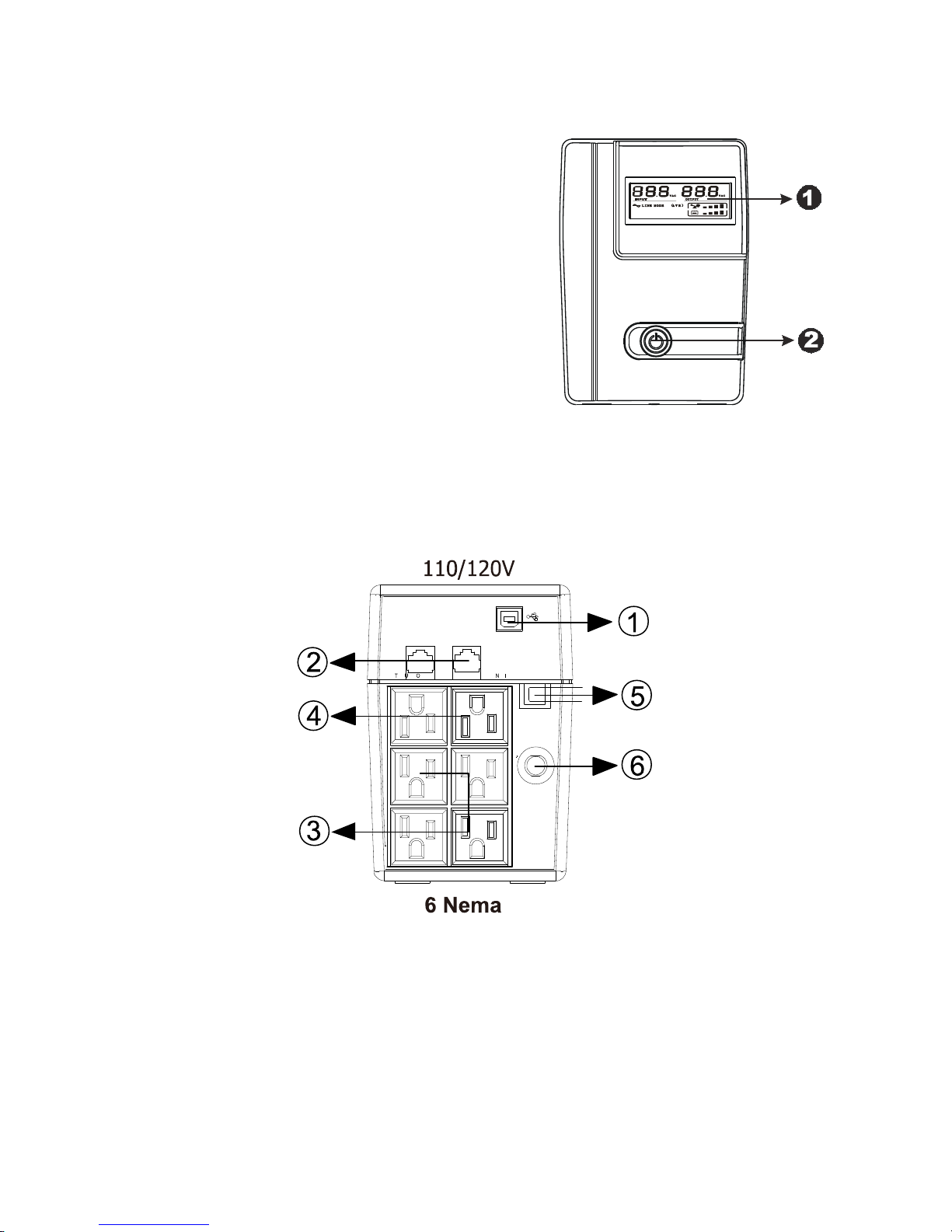
Front Panel—
1. LCD Back-Light
2. Power “ON/OFF” Switch
Back Panel—
1. Communication Port(Option)
2. Modem/Phone Line Surge Protection
3. AC Output
4. AC Input
5. FUSE
6. BREAKER
Page 6
Installation and Operation
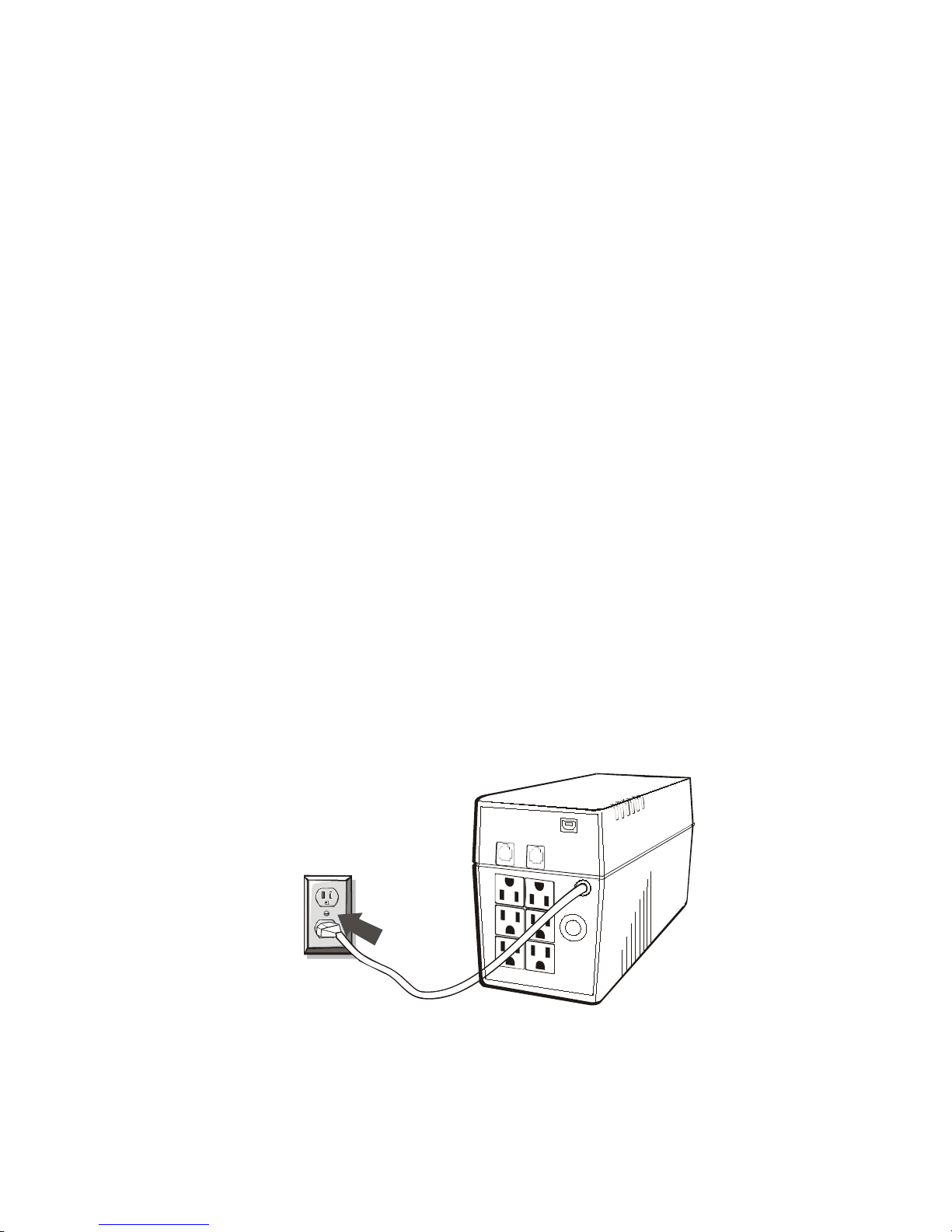
Installing the UPS is as easy as following the steps shown. Be
aware of the Power Switch must be kept in the “ON” position,
otherwise, the UPS w ill be disab led and y our eq uipmen t will n ot be
protected during a power failure.
1. Inspection
Remove the UPS from its packaging and inspect it for damage that
may have occurred during shipping. If any damage is discovered,
repack the unit and return it to the place of purchase.
2. Placement
Install the UPS unit in any protected environment that provides
adequate airflow around the unit, and is free from excessive dust,
corrosive fumes and conductive contaminants. Do not operate your
UPS in an environment where the ambient temperature or humidity is
high. On the other hand , place t he UPS unit away from monitor at least
20cm to avoid interference.
3. Charging
This unit is shipped from the factory with its internal battery fully
charged. However, some energy may be lost during shipping so the
battery should be recharged before using it. Plug the unit into an
appropriate power supply and a llow the UPS to cha rge fully by leaving
it plugged in for 8 hours.
Page 7

4. Computer Connec tion
Connect one computer-related device into each of the power
receptacles supplied on the back of the UPS (maximum of three
devices).
5. Modem/Phon eline Connecti on
Plug incoming internet l ine i nto the “In” so cket at the back o f the UPS.
Use one more Internet line cable and plug one end of the Internet line
cable to the “Out” socket at the back of the UPS. Plug the other end to
the modem input socket as shown.
6. S eri al Cable Connecti on
To allow for unattended system shutdown for your operating system,
connect the serial cable as per diagram below.
Page 8
7. Turn On/Off
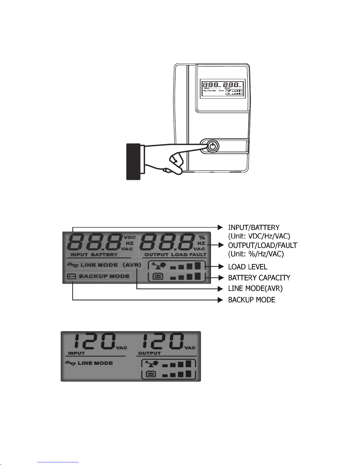
To turn on the UPS unit, press the power switch lightly. To turn off
the UPS unit, press the power swit ch again (When swith ON,The LCD
lighting.)
8. LCD Display Specification
When LCD start to work, it will display all information for 3s
a. When in normal mode, it will display as below.
Page 9
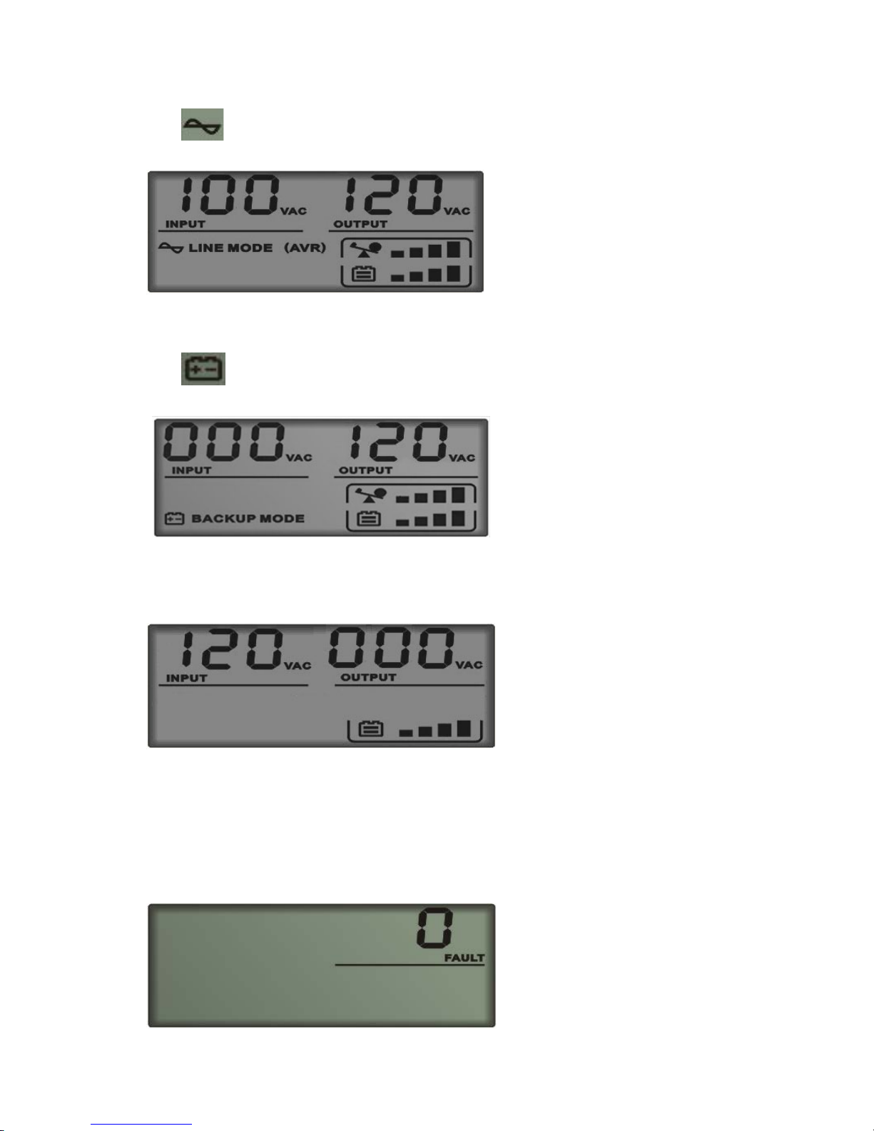
b. When in AVR mode, it will display as below. And the mark
will flicker every 1second.
c. When in battery mode, it will display as below. And the mark
will flicker every 1second.
Note: If I/P-V<20V,input voltage will display “000”
d. When in off charging mode, it will display as below.
Note: the output voltage always is displayed as “000” in off
charging mode.
e. When in fault mode, it will display as below. “FAULT”
character and the reason of fault only.
Page 10
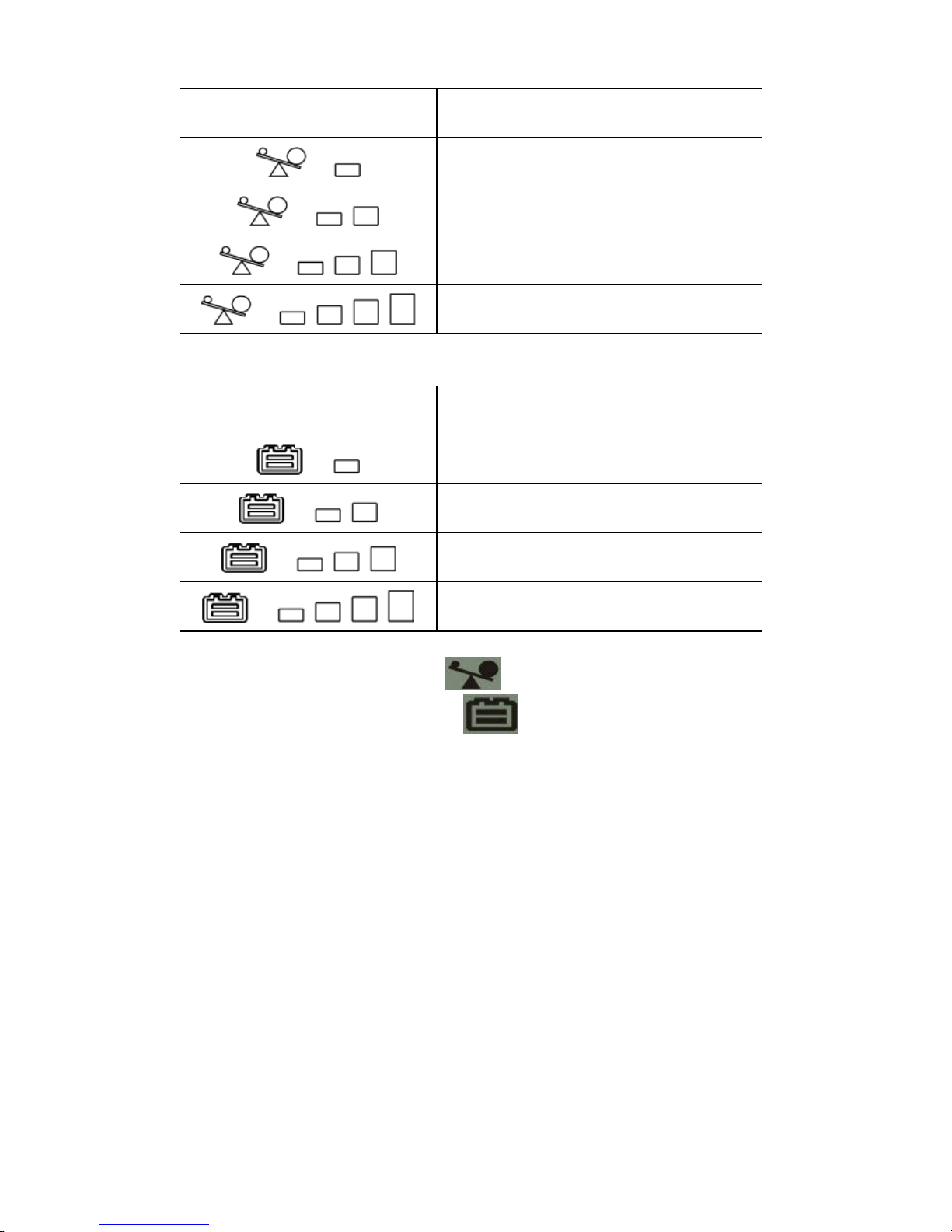
6).Load level definition:
Load LEVEL Load bar Indication
0%~25%
25%~50%
50%~75%
75%~100%
7).Battery capacity definition:
Battery LEVEL Battery bar Indication
Battery voltage≤11V
11V≤Battery voltage≤11.5V
11.5V≤Battery voltage≤12.5V
Battery voltage≥12.5V
8).When over load, the mark
will flicker every 1second.
9).When battery lo w, the mark
will flicker every 1second.
Page 11
Software Installation
-- WinPower --
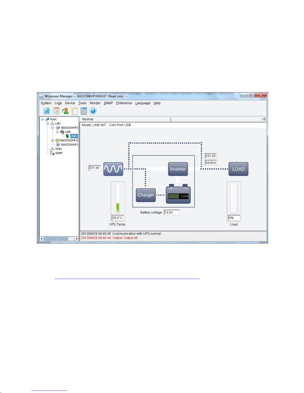
WinPower is a brand new UPS monitoring software, which provides
user-friendly interface to monitor and control your UPS. This unique
software provides safely auto shutdown for multi-computer systems while
power failure. With this software, users can monitor and control any UPS
on the same LAN no matter how far from the UPSs
Installation procedure:
1. Go to the website:
http://www.ups-software-download.com/index.htm
2. Choose the operation system you need and follow the instruction
described on the website to download the software.
3. When downloading all required files from the internet, enter the serial
No: 511C1-01220-0100-478DF2A to install the software.
Page 12

Trouble S hoot ing
Use the table below to solve minor UPS installation or operation
problems. If any abnormal situations occur that are not listed
above, please call ser v i ce people immediately.
Symptom Possible Cause Remedy
No LCD display on
the front panel.
1. Missing battery.
1. Charge battery up to 8
hours.
2. Battery defect.
2. Replace with the same type
of battery.
3.When the Input cord
isn’t electvified and
Power switch is not
pressed.
3. Press the power switch
again or elecerity the Input
cord
Alarm buzzer
beeps
continuously
when AC supply is
normal.
Overload of the UPS.
Verify that the load matches
the UPS capability specified in
the specs.
When power
failure, back-up
time is shorten.
1. Overload of the UPS.
1. Remove some noncritical
load.
2. Battery voltage is too
low.
2. Charge battery 8 hours or
more.
3. Battery defect due to
high temperature
operation environment,
or improper operation
to battery.
3. Replace with the same type
of battery.
Communication
lost between UPS
and computer.
1. Software is not
installed well.
1. Check the setting of the
software .
2. Cable is not properly
connected.
2. Check the USB cable is
firmly connected to
COM1/COM2 of the
computer and confirm the
setting again.
Mains normal but
LCD display
Battery mode.
1. Fuse is blown.
1. Replace the same type of
fuse.
2. Power cord is loose.
2. Reconnect the power cord
properly.
Page 13

Specification
MODEL
Vesta PRO 600 VAC Vesta PRO 800 VAC
CAPACITY VA/W 600/360 800/480
INPUT
Voltage Range 89-145VAC
Frequency 50Hz/60Hz 50Hz/60Hz
OUTPUT
Voltage 120VAC(110VAC)
Voltage Regulation +/- 10%(Battery Mode)
Frequency 50Hz/60Hz
Frequency Regulation +/-1 Hz(Battery Mode)
Output Wav eform Stepped Sine-wave
BATTERY
Battery Type 12V/7Ah 12V/9Ah
Back up Time
(One PC+15’’Monitor)
20 mins 29 mins
Rechar ge Time 6 hours to 90% at normal mode after complete discharge
TRANSFER
TIME
Typical 2-6ms typical, 10 ms max
INDICATOR LCD Display Models
The LCD will always turn on when UPS work,
Including in off charging mode and fault mode
AUDIBLE
ALARM
Backup Mode Sounding every 10 seconds
Battery Low Sounding every 1 second
Overload Sounding every 0.5 seconds
Battery replace Sounding every 2 seconds
Fault Continuous sounding
Buck/boost with
>70% SPS load
Sounding every 0.5sec. after 25min.
And fault after 30 mins
PROTECTION Full Protection
Discharge,Overcharge short circuit
and Overload Protection
PHYSICAL
Dimension (DxWxD)
(mm)
330* 100 * 140
WEIGHT
Net Weight 13.2lb.(6kg) 14.3 lb.(6.5Kg)
ENVIRONMENT
Operating
Environment
0- 40°C, 0-90 % Relative Humidity (non-condensing)
Noise Level
Less than 40dB
INTERFACE
SmartRS-232
(optional)
Windows family, Sun Solaris, IBM Aix, Compaq True64,
UnixWare, FreeBSD, HP-UX, Linux and MAC
USB For Windows family & Mac
 Loading...