

Page 1
Quality does it.
Instruction Manual
ION/ PARTS CLEANER
No. IPC40-E
Application
This product is used to remove fine powder and dust attracted by static electricity and to remove static
electricity from parts that are negatively affected by static electricity.
A powerful air blower in an ionized space blows off the debris. The blown off debris is forcefully
collected by a dust collector.
Table of Contents
■For Your Safety ································ P.2
■Product Overview ···························· P.6
■Dimensions ······································ P.9
■Component Functions ····················· P.10
■Installation ······································· P.13
■Operation ········································· P.19
■Maintenance ···································· P.27
■Storage &Troubleshooting ··········· P.33
■Removing, Disposing of,
and Replacing Parts ······················ P.34
■Notice of CE Marking ···················· P.35
Page 2
For Your Safely
Safety Precautions
Please read this manual carefully before using this product.
Use this manual to take responsibility to ensure everyone that is using this product is doing so safely.
After carefully reading this manual, keep it in a protected place where it can be used at any time.
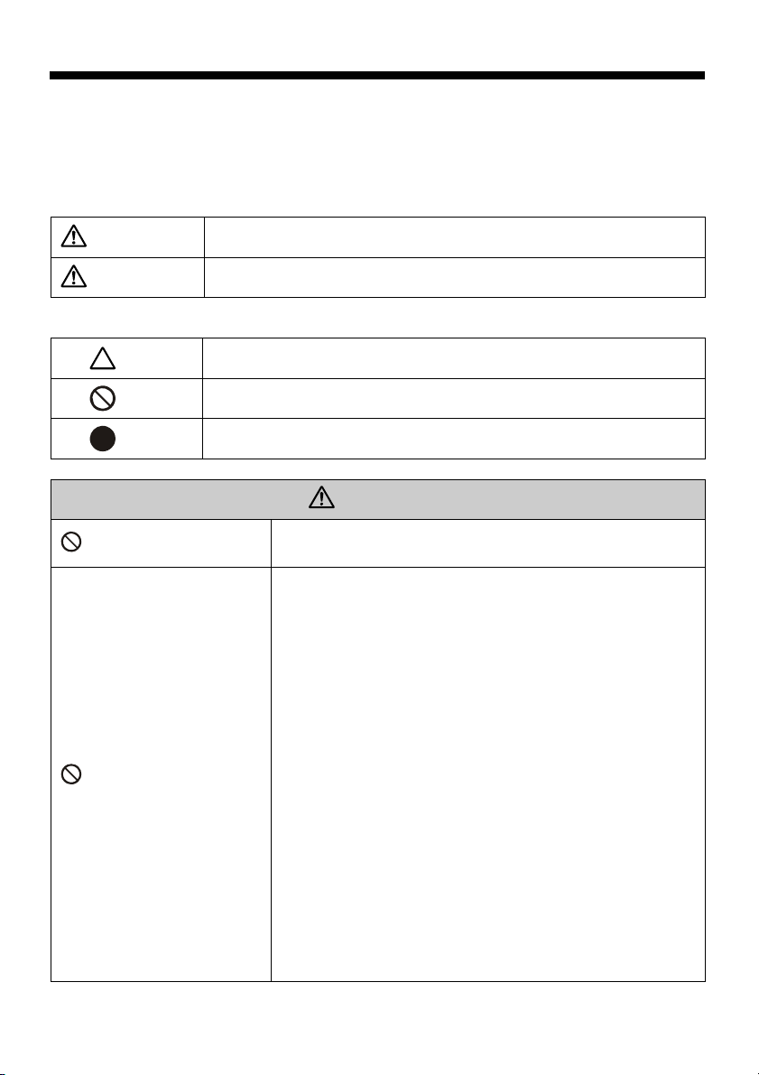
●The precaution items shown here are divided into two levels according to the level or risk.
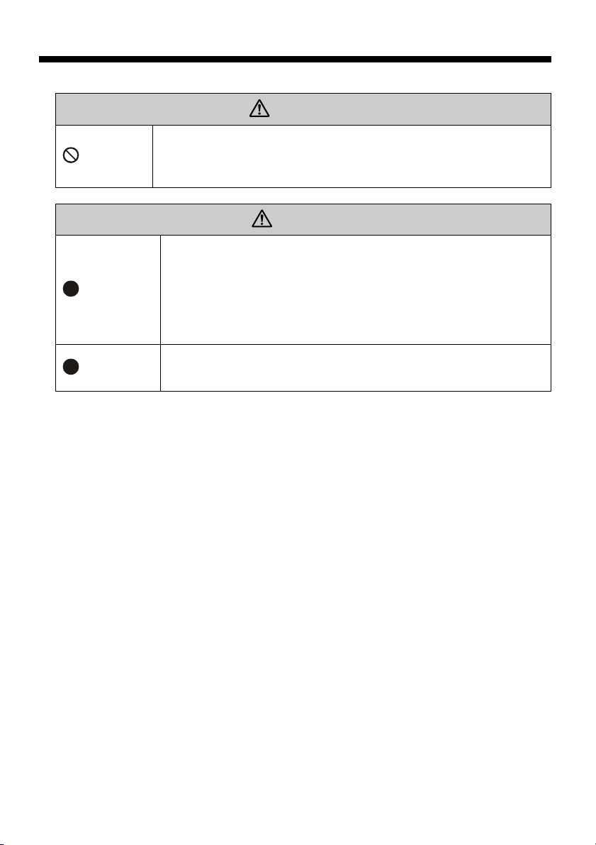
WARNING
CAUTION
○Example Pictorial Displays
Indicates that improper handling can lead to serious injury or even death.
Indicates that improper handling can lead to minor injury and property
damage.
This symbol indicates a WARNING or CAUTION.
Prohibited
Vacuuming Up Prohibited
This symbol indicates a prohibited action.
This symbol indicates a mandatory required action
WARNING
Do not use IPC40-E for anything other than static erasure or dust
removal.
To prevent fires, absolutely do not vacuum up flames, explosive
dust, or liquid mist containing dust such as the following.
- Items that are on fire: Cigarette butts, matches, and other
sources of fire.
- Things containing sparks: A large amount of sparks from
grinding, dust that includes cinders, etc.
- Flammable substances: Gasoline, thinner, benzene,
kerosene, materials adhered with or containing oils, cleaning
fluids, or flammable substances.
- Explosive substances: Explosive dust, such as aluminum,
magnesium, titanium, and epoxy resin; explosive materials
and dust or explosive liquids that can make dust explode
depending on the conditions such as particle diameter and
concentration; liquid mists or substances adhered with or
containing explosive substances.
- Combustible substances: Combustible dust, combustible
liquid mist, or materials adhered with or containing
combustible materials, etc.
2
Page 3
Vacuuming Up Prohibited
Vacuuming Up Prohibited
Joint Use Prohibited
Remember
Remember
Remember
Remember
For Your Safely
WARNING
- Detrimental substances: Corrosive substances, adhesive
substances, liquids containing adhesive substances, gases
Take into consideration the conditions surrounding the installation area.
・ Install the unit in an indoor location not subject to wind, rain, or direct
sunlight.
・ Where possibly wet by water, oil, chemicals, etc.
・ Where exposed to marked vibrations or shock
・ The temperature range should be 0°C to 40°C. Use the unit in a humidity
range of 20 to 80%.
To prevent fires, conduct an inspection after work is completed.
Be sure to correctly install the components.
Leaks from defective installation could overload the motor and cause it to
burn out.
Store this manual close to the product where it can be referenced easily.
containing large quantities of detrimental substances, etc.
- Liquids and liquid mists: Dust containing moisture such as
that generated by machine tools, etc.
To prevent an accident or malfunction, absolutely do not
vacuum up damp dust or any moisture such as water or oil.
Damp dust could clog the filter and make recovery impossible.
Further, the product is not moisture or oil resistant, so an
unforeseen malfunction or accident could occur due to
corrosion, leaking, and dust accumulating in the internal duct.
To prevent fires, absolutely do not make joint use of the
following.
・ When the dust could transform into a hazardous substance
when mixed inside the unit.
CAUTION
Prohibited
Do not install, use, or service this product until you understand this manual.
3
Page 4
For Your Safely
WARNING
Prohibited
Painting Prohibited
Peering Prohibited
Disassembly Prohibited
Acceleration Prohibited
Remember
To prevent fires, only use the specified rated power source.
Use as a painting booth is prohibited. Do not perform painting
work in it.
Do not peer into the end of the air nozzle. The sensor will
detect your presence and blast out compressed air, which
could strike your eyes or face.
WARNING
Do not remove components, or modify or unreasonably
disassemble or assemble the product.
・ This product is manufactured in accordance with safety and
performance standards, so removing components or
modifying the product is dangerous.
・ Depending on the type of trouble, the customer might not be
able to handle it, so always contact the store where the
product was purchased.
Do not use an inverter to accelerate operation.
Acceleration could overload the motor and pose a hazard in
terms of the strength of rotating parts, etc. In addition,
deceleration could cause a drop in blow volume, which could
result in insufficient motor cooling.
Be sure to observe the following to prevent electrical shock
accidents.
・ Be sure to unplug the power cord from the outlet before
performing any wiring.
Remember
Remember
Remember
WARNING
Be sure to turn off the power when the thermal protector operates and the
operation stops.
When the motor becomes overloaded, the thermal protector automatically
operates to stop the motor, but since this is an automatic recovery type motor,
if the power is left on, the motor could suddenly automatically restarting
operating and leads to an accident.
Turn off the power switch and main power supply before looking for the cause
of the problem.
Do not restart operation before identifying and eliminating the cause of the
problem.
Perform the processing quickly without letting dust accumulate.
Depending on the conditions, dust could present a fire or explosion hazard.
Be sure to unplug the power cord from the outlet before performing any
maintenance or inspection work.
4
Page 5
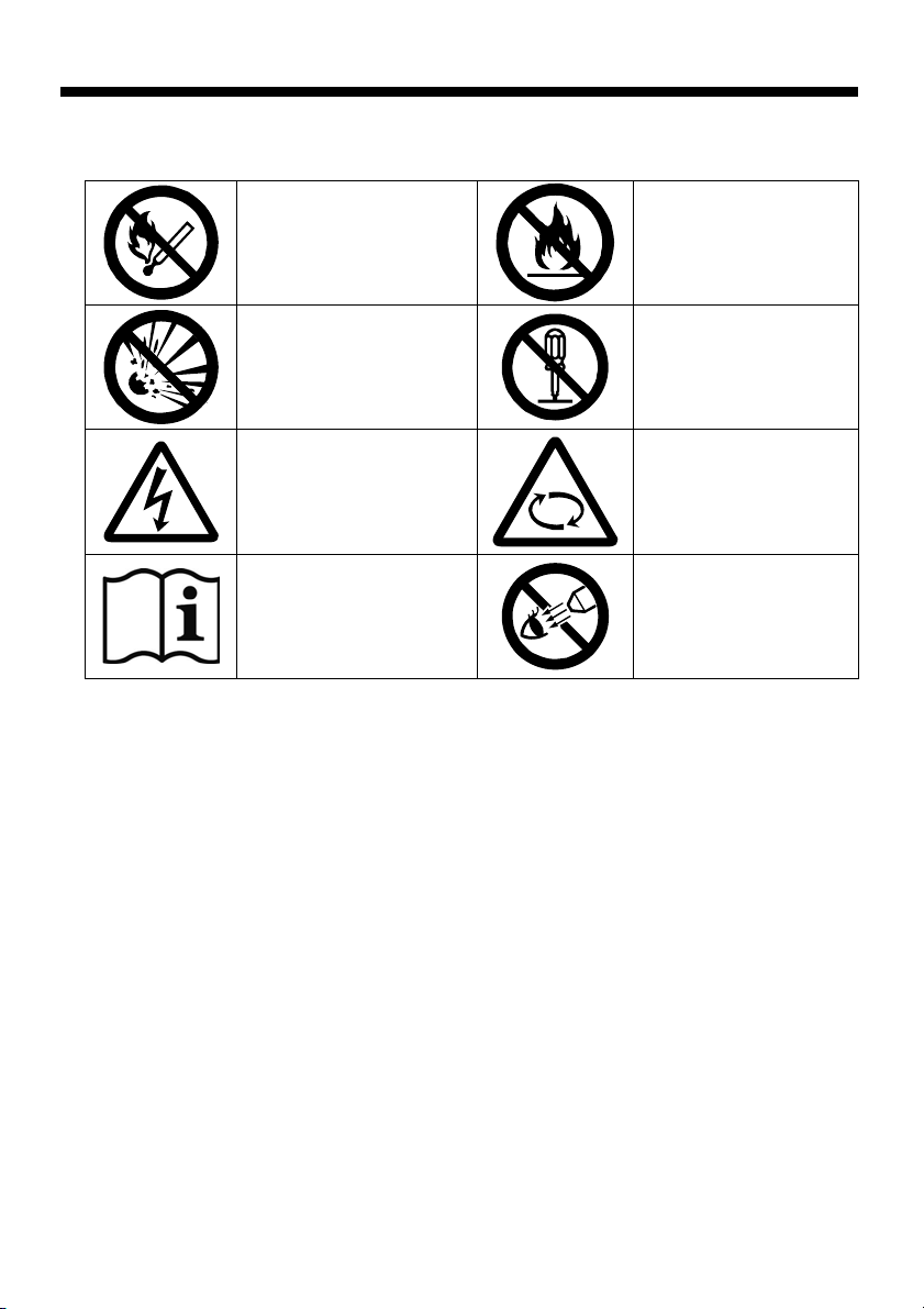
To Use this Product Safely
The following prohibition and caution symbols are displayed on the product.
○Example Pictorial Displays
Sucking up sparks or
flames is prohibited
Sucking up explosive
substances is prohibited
Be careful of electric shock
Carefully read the
instruction manual
5
Sucking up flammable or
combustible substances
is prohibited
Disassembly Prohibited
Be careful of rotating
parts
No Peeking for Air Nozzle
Page 6

Product Overview
Features
●Dust collecting unit with a static eraser
・This is a separate type static eraser dust collector where the work hood and dust collector are
connected by a duct and a connection cord.
・The work hood and dust collector can be installed in separate, freely selected locations to make
effective use of limited working space.
・The dust collector can be placed under the bench or in another location to muffle the noise.
●Work hood
・The entire top of the hood is made of transparent acrylic. This lets in light to provide good visibility.
・The wide opening makes it easy to insert and remove long pieces of work.
・Connecting electrical power and the drive source to the static eraser dust collector maintains an
environment filled with ions inside the hood.
・The sensor detects when work held by hand is placed inside the hood and automatically turns on the
air blower.
・The dust is instantly removed from even large pieces of work by the two air nozzles that blow air from
the left and right.
●Dust collecting unit
・ Built-in high-performance filter for removing fine, dry dust. The exhaust does not dirty the room air.
・ A closable clear acrylic window is provided in the front of the hood to block flying material and provide
good visibility.
・ The opening has been optimally designed to allow the work to be smoothly put in and removed.
・ The dust collector filter can be easily replaced by removing the front cover.
●Safety
・ The static eraser has a problem monitoring function that can be checked by looking at the illuminated
indicators, etc.
・ Equipped with a control circuit that first vents the air from inside the dust collector hood before turning
on the static eraser power.
CE Marking
We have certified our manufactured IPC40-E are designed and manufactured under the
requirement of EU directive with following conditions:
○Low voltage Directive (73/23/EEC)
REQUIREMENTS : IEC/EN60335-1, IEC/EN60335-2-80, IEC/EN55014-1,
IEC/EN55014-2, IEC/EN61000-3-2, IEC/EN61000-3-3, IEC/EN60204-1
○POLLUTION DEGREE : II
○IP Code : IP2X
6
Page 7
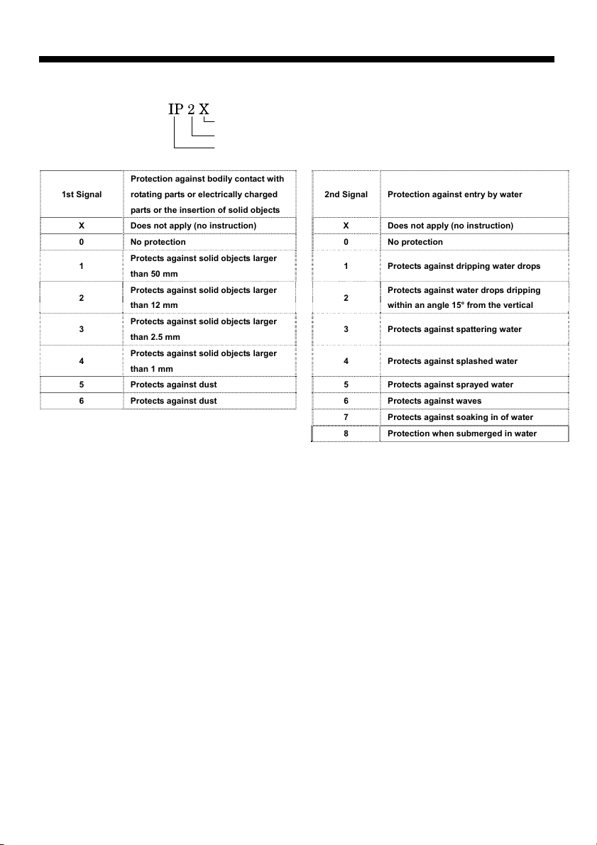
Product Overview
Protection Classification (IP) Labeling Examples
Protection against bodily contact with
1st Signal
X Does not apply (no instruction) X Does not apply (no instruction)
0 No protection 0 No protection
1
2
3
4
5 Protects against dust 5 Protects against sprayed water
6 Protects against dust 6 Protects against waves
7 Protects against soaking in of water
8 Protection when submerged in water
rotating parts or electrically charged
parts or the insertion of solid objects
Protects against solid objects larger
than 50 mm
Protects against solid objects larger
than 12 mm
Protects against solid objects larger
than 2.5 mm
Protects against solid objects larger
than 1 mm
2nd signal
1st signal
Character signal
2nd Signal Protection against entry by water
1 Protects against dripping water drops
2
3 Protects against spattering water
4 Protects against splashed water
Protects against water drops dripping
within an angle 15° from the vertical
7
Page 8

Product Overview
Model No. : IPC40-E
Dust Collection Method : Cylindrical Cartridge Filter
Input Voltage : Single-phase AC 230V (50/60Hz)
Power Output : 200W
Consumption Current : 1.2A (50Hz) 1.4A (60Hz)
Air Flow : 3.3 m
Static Pressure : 0.88kPa (50Hz) 1.23kPa (60Hz)
Wind Pressure : 0.4 m/sec (50Hz) 0.5 m/sec (60Hz)
Dust Collection : 1.2L
Air Pressure/Air Hose : 0.4~0.7MPa (Use clean air) /φ6mm x φ4mm
Air Consumption : 355 ℓ / min. (0.7MPa, actual measurement))
Working Temperature/ Humidity Range : 0~+40℃ / 20~80%RH (No dewing or freezing)
Noise : Hood Front 63dB(A) (50Hz) 66dB(A) (60Hz)
Dust Collector Front 62dB(A) (50Hz) 65dB(A) (60Hz)
Dimensions :Hood 518W×462D×402H(mm)
Dust Collector 481W×354D×416H(mm)
Weight : Hood 12kg
Dust Collector 30kg
Connection cord
Accessories
Option :High-brightness LED unit This optional LED unit lights up the
workspace, helping workers to detect dust.
●Specifications (Static Eraser)
Model No. : SDJ-08
Ion Generation Method : High voltage AC corona discharge
Output voltage :±3.5 KV AC
Input voltage : 24V DC ±5%
Consumption Current : 200mA (typ.)
Air Flow : 0.8 ㎥/ min. (max.) ⇔ 0.4 ㎥/ min.
Warning output : NPN transistor / open collector, max. rating: 100 mA/ 50V
high voltage alarm (Red LED), fan lock alarm (Red LED)
Protective function : Over current protection fuse (1.8 A/50 V)
Reverse-current connector protection diode (1.0 A/ 400 V)
Fan motor rotation monitoring function (Detecting rotation lock)
High-voltage output drooping (Detecting overload)
Working temperature/ Humidity Range: 0 ~+40℃ 20~80%RH (No dewing or freezing)
Ozone generation : 0.007 ppm or less (As measured at 300 mm, 30 sec.)
Static electricity removal time : About 2.9 sec. from ±1,000 V ⇔ ±100 V
Ion balance : Within ±10 V (At 300 mm, maximum air flow)
3
/min (50Hz) 4.0 m3/min (60Hz)
:Connector type Length 1.6 m
:Instruction Manual (this manual) 1cop.
Static eraser dust remover adjustment tool 1pc
Sensor plastic adjustment tool 1pc
Dangerous use prohibited card 1pc
Clear acrylic sheet 1pc
Thumbscrews (M4-6) 6pcs
Dust collection duct hose (1.6 m) 1pc
(At 300 mm, maximum air flow)
8
Page 9
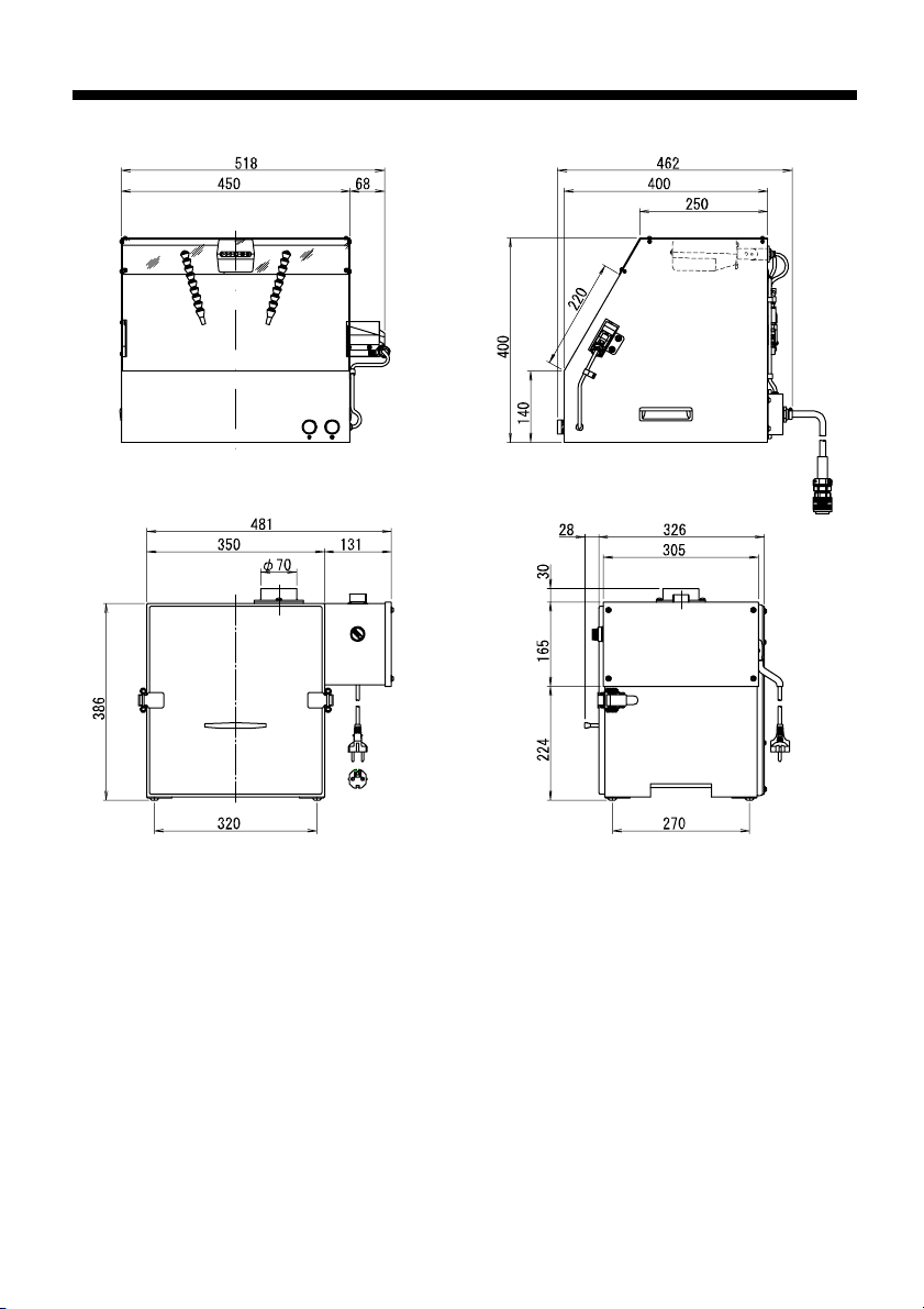
■Dimensions
9
Page 10
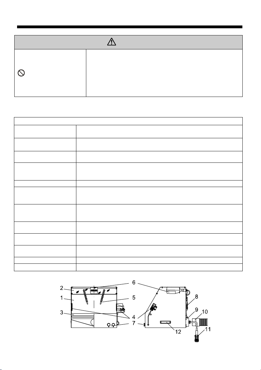
■Component Functions
CAUTION
Absolutely do not replace the hood or dust collector with another
device or use a substitute device.
Do not remove components, or modify or unreasonably disassemble
Disassembly Prohibited
Please be sure to understand the components and functions of the dust collector work platform and to
operate the unit safely and to work safely.
1. Work hood
2. Clear acrylic sheet
3. Perforated plate
4. Sensor + reflection
plate
5. Air nozzles Two flexible nozzles that can be pointed in any direction.
6. Static eraser
7. Operation button
8. Air solenoid valve
9. Duct connection port
(exhaust)
10. Dust collection duct
hose
11. Connection cord This is a 1.6 m long connection cord for connecting to the dust collector.
12. Handle This is used to hold the hood when moving it.
or assemble the product.
This product is manufactured in accordance with safety and
performance standards, so removing components or modifying the
product is dangerous.
Work Hood
This is a booth that improves the dust collection effectiveness of the dust
removal work.
This plate keeps dust from dispersing during the dust removal work. It
also lets in light from the top to allow the work surface to be clearly seen.
This is a work plate for use during the work. It prevents large objects from
falling inside the chamber.
This senses when work is put in or removed and sends a signal to the air
solenoid valve. For information about the sensitivity and timer, refer to
the “Sensor” item under “Operation” in this manual.
This removes electrostatic charge. For information regarding the detailed
operation of the SDJ-08 Static Eraser, refer to the “Static Eraser” item
under “Operation” in this manual.
This button is located close to the dust collector and is used to start and
stop the operation. A push button type main switch is attached to the dust
collector.
This supplies or stops the compressed air in response to the sensor
signal.
This connects the duct to the dust collector.
Bellows type with a length of 1.6 m when extended.
10
Page 11
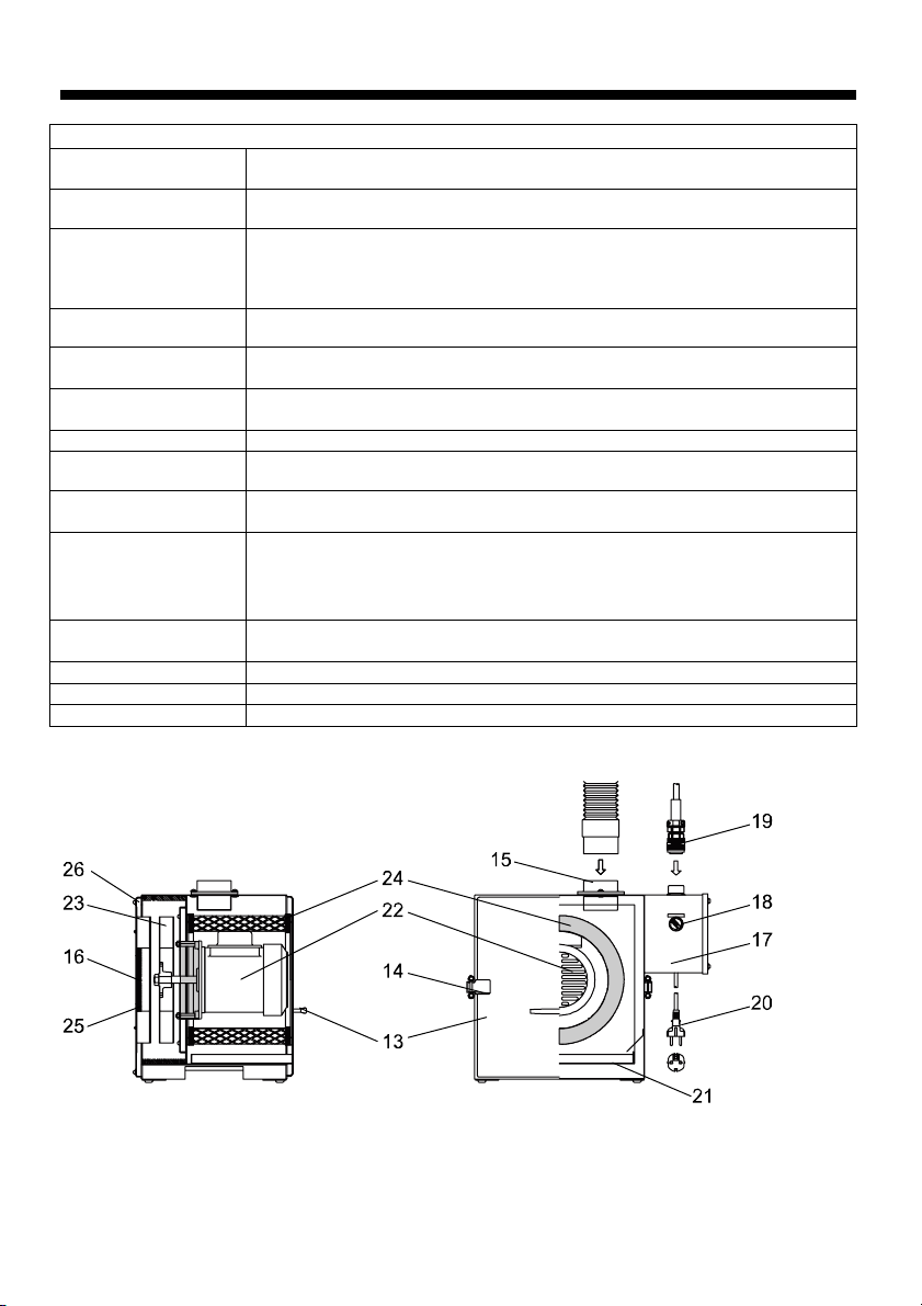
■Component Functions
13. Front cover
14. Thumb lock This lock is used to fasten the front cover.
Removable opening through which the filter unit can be installed and
removed.
Dust Collector
15. Duct connection
port (suction)
16. Exhaust port This is from where the clean air is exhausted.
17. Control box
18. Main switch
19. Connector This connector is for a connection cord that connects to the work hood.
20. Power cord Cabtyre cord with insertion plug.
21. Draw tray
22. Fan motor
23. Fan
24. Filter unit The filter unit removes dust.
25. Rear filter This is installed in the rear cover as the unit’s final filter.
26. Rear cover This covers the area containing the fan.
This connects the duct to the work hood.
This contains a circuit that turns on the static eraser dust collector about 7
sec after the operation switch is turned on.
This switch turns the power to the control box on and off. It is a selector type
switch.
This tray collects the removed dust or dropped powder dust.
The draw in the front cover is removed to dispose of the dust.
This is the drive unit that turns the fan. It has a built-in thermal protector.
When the temperature inside the motor reaches approximately 120°C, the
motor automatically stops, and when it cools again to approximately 80°C
after stopping, it automatically restarts.
This generates speed and pressure in the air and provides vacuum force to
the dust collector.
11
Page 12
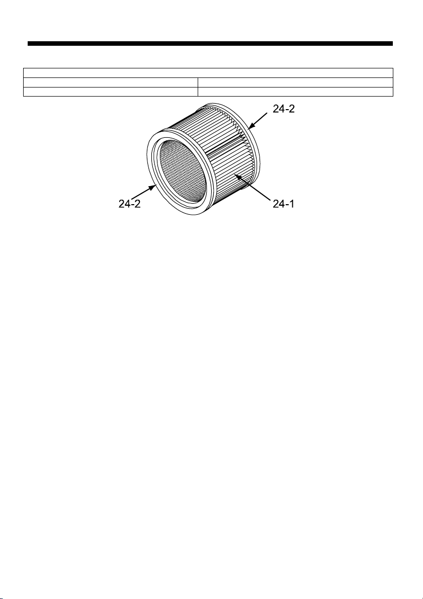
■Component Functions
24-1. Cylindrical cassette filter (non-cloth) Number used by one unit: 1
24-2. Filter packing Number used by one unit: 2
Filter unit part names
12
Page 13
Installation
Installation Area
WARNING
Do not use this product in the following areas. Where there is a risk of an
Prohibited
Remember
Remember
Installation Area
Install the unit in an indoor location not subject to wind, rain, or direct sunlight.
Avoid using the unit in areas where water, oil, or condensation will get on it or where it will be
subject to sudden temperature changes.
Avoid using the unit where it will be subject to strong vibration or impacts.
An exhaust outlet is provided on the back of this unit, so placing the back of the unit close to the
wall will prevent normal exhausting and decrease the dust collecting capability. Install the unit
with its back at least 10 cm from the wall.
Ambient temperature and humidity
Use in a temperature range of 0°C to +40°C. Use the unit in a humidity range of 20 to 80%.
Atmosphere
Do not operate the unit in environments where anti-explosion measures are required.
Do not operate the unit in areas where corrosive gases or flammable or explosive gases are
used. In addition, use the unit in a well ventilated area with a normal air atmosphere.
Input voltage and compressed air
This unit uses AC 230V (50/60 Hz) input voltage and 0.4 MPa to 0.7 MPa compressed air for the
cleaning air. Install the unit where it can be connected to wiring and piping that meet these
specifications.
Maintenance space
Space for maintenance and inspections should be maintained around the unit.
In particular, the space in front of the unit required for daily maintenance should be obtained.
explosion or fire.
・ Environments that require anti-explosion measures.
・ Areas where corrosive gases or flammable or explosive gases are used.
CAUTION
Take into consideration the conditions surrounding the installation area.
・ Install the unit in an indoor location not subject to wind, rain, or direct
sunlight.
・ Where possibly wet by water, oil, chemicals, etc.
・ Where excessive vibration or shock is applied to the unit.
・ Use in a temperature range of 0°C to +40°C. Use the unit in a humidity
range of 20 to 80%.
Do not use this product where it will be directly exposed to high
temperatures or high humidity. Doing so could cause the motor to burn
out or breakdown.
13
Page 14
Installation
Installation Method
When installing this unit, place it on a level, strong, and smooth, flat bench.
WARNING
Remember
Remember
CAUTION
Accessory Installation
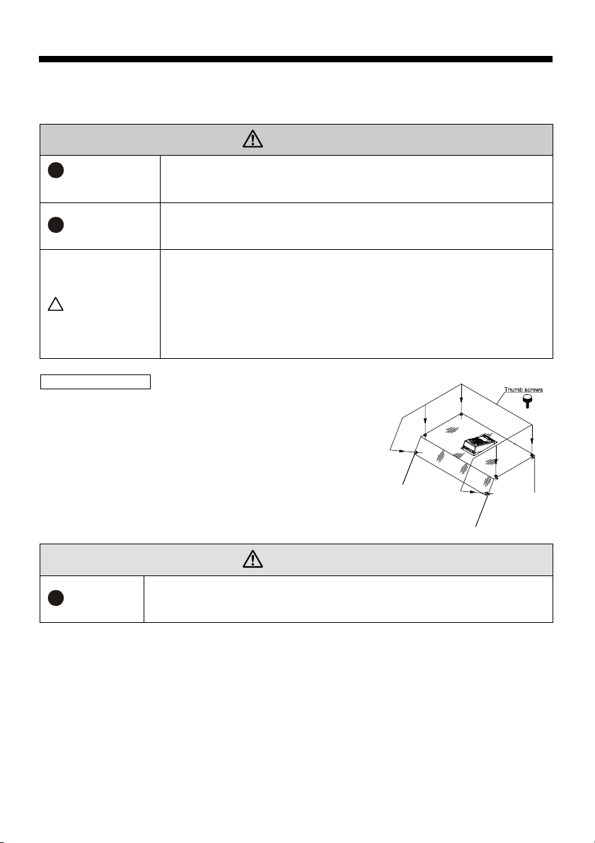
Clear acrylic sheet installation
The work hood top acrylic sheet is removed from the hood and
packed to prevent it from being broken during product shipment.
Before using the unit, install the clear plastic sheet using the
included 6 thumbscrews.
The position of the thumbscrews is shown in the figure
at right.
Remember
To keep the unit from falling over, do not climb on the working surface or
place heavy objects on it.
When installing the IPC40-E, place it on a level, strong, and smooth, flat
bench.
It can be damaged and malfunction if it falls.
Check the following, being aware of the weight of the product.
・ Be sufficiently careful that no part of the body, especially fingers and toes,
will be caught underneath the product while it is being installed or moved.
・ Make sure the product does not fall over while it is being installed or
moved.
・ Do not move the product while an object is set on its hood. The object
could fall off of the hood.
WARNING
The work hood tope clear acrylic sheet prevents dust from being dispersed
during dust collection. The included clear acrylic sheet should always be
installed while working.
14
Page 15
Installation
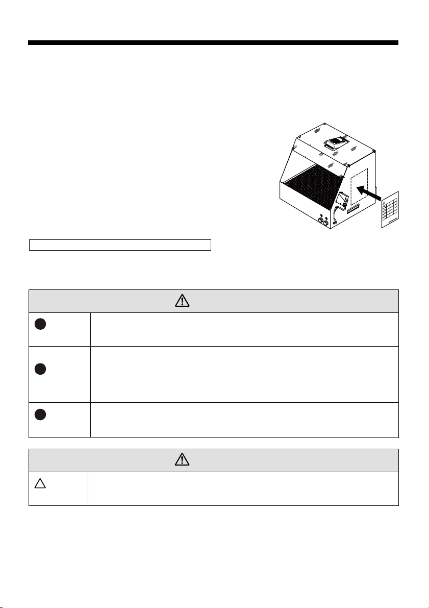
Dangerous use prohibited card application
The person in charge of controlling the use of this product must agree with the “Dangerous use
prohibited” items written on the included dangerous use prohibited card.
This person must sign on the signature line of the card and affix it to the side of the work hood or
other place clearly seen.
Connecting the work hood and dust collector
When the installation location has been decided, connect the connection cord coming from the work
hood and the included dust collection duct hose.
WARNING
Remember
Remember
Remember
To prevent electrical shock accidents, be sure to unplug the power cord from the
outlet before performing any wiring.
To ensure safety, the work hood and dust collector shall be set up as prescribed by
this manual. Do not remove components, or modify or unreasonably disassemble
or assemble the product. This product is manufactured in accordance with safety
and performance standards, so removing components or modifying the product is
dangerous.
Do not attach extensions to the dust collection duct hose or the connection cord.
Doing so could cause the timer setting of linked equipment not to match,
preventing correct operation.
CAUTION
CAUTION
Firmly connect the dust collection duct hose and the connection cord so that they
do not come loose during operation. Checking/inspecting these before starting work
are recommended.
15
Page 16
Installation
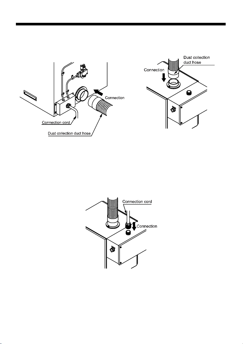
Dust collection duct hose connection
Connect the included dust collection duct hose to the exhaust port on the rear of the work hood and
the suction port on the top of the dust collector. The connection positions are shown in the figures
below.
Connection cord connection
Connect the connection cord coming from the rear of the work hood to the connector on top of the
dust collector. A connector is used to make it easy to connect to the dust collector. The connection
position is shown in the figure at right.
16
Page 17
Installation
Compressed air piping
CAUTION
Remember
Compressed air used
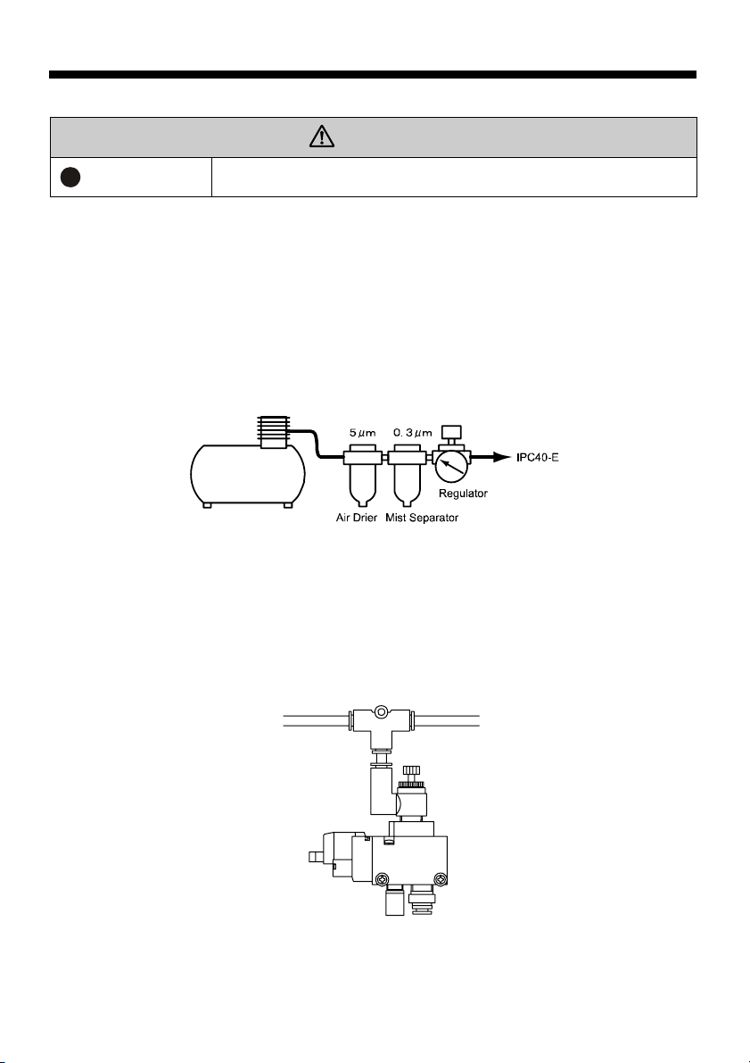
This unit requires that clean compressed air be supplied to the dust removal air blower.
Supply air within the pressure range of 0.4 to 0.7 MPa.
*A pilot solenoid valve is used to assist the operation of the valve used to supply the compressed
Use an air drier to remove the moisture from the air. (The dew point temperature is -15°C or
lower.) Use mist separator (0.3 μm) to remove the impurities from the air.
Supply air within the temperature range of 0 to +40°C.
Hose used
Use an air hose with sufficient pressure resistance performance (outside diameter 6 mm x inside
diameter 4 mm).
Hose connection
Connect the hose to the one-touch hose coupling (compressed air supply opening) on the bottom of
the solenoid valve on the back of the work hood. Refer to the following figure.
air, and it will not operate properly if the supply pressure is too low.
Be sure to use an air hose with sufficient pressure resistance
performance. A hose without pressure resistance could burst or leak air.
17
Page 18
Installation
Electrical power wiring
WARNING
Remember
Remember
Remember
Check the specifications
Check to make sure the specifications of the supplied power makes the unit’s power specifications.
Wiring circuit breaker
Use a wiring circuit breaker to prevent overloading. It is also recommended that a ground-fault
interrupter be installed.
Extension cord
When an extension cord is used to supply power from a distant location, if the core wire of the
extension cord is narrow, it could cause a voltage drop and make it difficult for the unit to start and
prevent the capacity from being fully realized, so make sure the extension cord has sufficient
capacity to carry the electrical load. In addition, carrying a current that exceeds the allowable current
value could damage the cord’s insulation.
Power cord
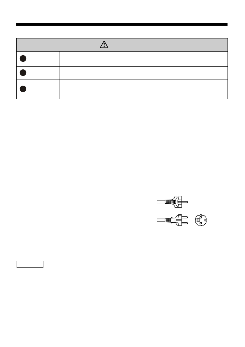
The power cord comes with a plug, so plug it completely
into the oulet (230V AC).
Static eraser
The static eraser’s operation mode selector switch is set to automatic operation to link operation with
this unit.
Use IPC40-E only with 230V AC(50/60Hz). Use of other voltage may result in
fire and electric shock.
To prevent electrical shock accidents, be sure to unplug the power cord from
the outlet before performing any wiring.
To prevent electrical leaks, electrical shocks, and fire accidents, perform the
wiring work in accordance with electrical equipment technology standards and
in-house wiring provisions.
Duct piping
Exhaust port
An exhaust port is provided on the rear of the dust collector.
The flange for connecting ducts with a 100 mm inside diameter is an option.
*Please be aware that connecting a duct will reduce the dust collecting capability.
18
Page 19
Operation
Operation
Before starting operation, double check to make sure all of the installation items are being observed.
Make sure there are no problems with the unit.
・Is there any damage, loose screws, or loose connectors?
・Are all of the front and rear covers completely shut?
・Have the dust collection duct hose or connection cord come loose?
Operation
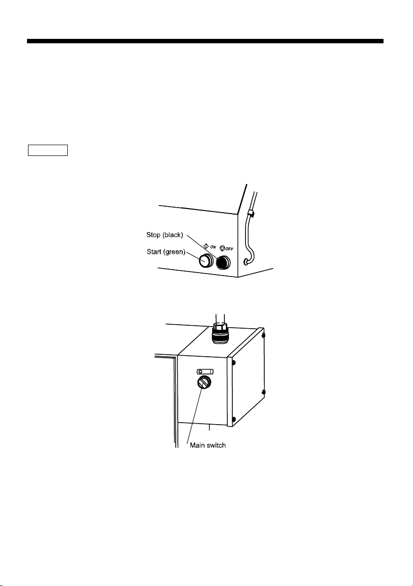
Operation is performed using the Start (green) and Stop (black) push buttons on the front of the work
hood.
The selector switch on the front of the dust collector is the main switch. Turn this from OFF (○) to ON
(|) before beginning operation.
・Use a wiring circuit breaker (for the motor) to prevent overloading.
・In this case, use one that is suitable for the motor (suitable for the current value).
・It is also recommended that a ground-fault interrupter be installed.
19
Page 20
Operation
WARNING
Be sure to turn off the power when the thermal protector operates and
the operation stops.
When the motor becomes overloaded, the thermal protector
automatically operates to stop the motor, but since this is an
Remember
automatic recovery type motor, if the power is left on, the motor could
suddenly automatically restarting operating and lead to an accident.
Be sure to turn off the switch and unplug the power cord from the
outlet before looking for the cause of the trouble.
Do not restart operation before identifying and eliminating the cause
of the trouble.
Perforated plate
This is used as a work platform. It prevents large-diameter objects from falling inside the unit.
CAUTION
Do not use the unit with this plate removed.
The sensor might not work properly.
If the perforated plate is deformed or broken while performing work,
continuing to use the product in this condition is hazardous, so make
sure the perforated plate is properly maintained.
Replacing the deformed or damaged perforated plate is recommended.
This unit is designed for light work, such as handwork, so do not place
heavy objects on top of the perforated plate or forcefully strike it.
Doing so could deform or break the perforated plate.
The perforated plate is designed to support up to 10 kg.
Prohibited
CAUTION
Remember
Operating conditions
Perform operation under the following conditions.
Keep the power voltage within the allowable fluctuation range of within ±10%.
The frequency range shall be the rated frequency stated on the name plate.
Do not use an inverter to operate the unit.
The unit is designed to provide the specified performance when operated at the rated frequency.
Acceleration could overload the motor and pose a hazard in terms of part strength, and
deceleration could cause insufficient motor cooling.
Prohibited
WARNING
Using an inverter to acceleration operation could overload the motor and
pose a hazard in terms of the strength of rotating parts, so absolutely do not
do it.
20
Page 21

Operation
Dust conditions
Observe the following conditions for the dust that is handled.
●This unit is for use with regular dust. It can be used to blow off dry fine dust with compressed air.
Absolutely do not vacuum up wet dust, liquids like water, oil or spray mist.
Also absolutely do not vacuum up dust containing explosive, flammable, or combustible substances.
●Do not vacuum up adhesive or corrosive substances.
●To prevent fires, absolutely do not vacuum up flames, explosive dust, or liquid mist containing dust
such as the following.
- Items that are on fire: Cigarette butts, matches, and other sources of fire.
- Things containing sparks: A large amount of sparks from grinding, dust that includes cinders, etc.
- Flammable substances: Gasoline, thinner, benzene, kerosene, etc. Materials adhered with or
containing oils, cleaning fluids, or flammable substances.
- Explosive substances: Explosive dust, such as aluminum, magnesium, titanium, and epoxy resin;
explosive materials and dust or explosive liquids that can make dust explode depending on the
conditions such as particle diameter and concentration; liquid mists or substances adhered with or
containing explosive substances.
- Combustible substances: Combustible dust, combustible liquid mist, or materials adhered with or
containing combustible materials, etc.
●Do not vacuum up flammable dust or dust containing flammable substances.
Caution must be taken in particular with non-combustible substances that change into combustible
substances when worked on, etc.
It is very difficult to determine if such substances are changing into combustible dust, so we ask the
customer to be responsible for making this determination. In addition, if a substance is determined to
be combustible dust, immediately stop using this unit.
●Even if the individually handled dusts are safe, they may change into a hazardous substance when
mixed together. Caution is especially required for substances the change when mixed, so we ask
that the customer be responsible for checking this.
If the safety of mixed dust cannot be determined, absolutely do not use the same machine for both
kinds of materials.
Since an unexpected problem could occur in the disposal of mixed collected dust, we ask that the
customer be responsible for making this determination.
●Absolutely do not vacuum up damp dust or any moisture such as water or oil.
Collecting dust wet with a liquid or dusting containing a liquid could clog the filter and make operation
recovery impossible and, since the product is not moisture or oil resistant, so an unforeseen
malfunction or accident could occur due to corrosion, leaking, and dust accumulating in the internal
duct.
21
Page 22
Operation
Vacuuming Up Prohibited
Vacuuming Up Prohibited
Vacuuming Up Prohibited
Joint Use Prohibited
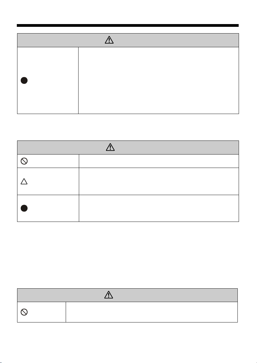
WARNING
Absolutely do not vacuum up sparks; flammable, explosive, of
combustible dust; or dust containing or mixed with explosive,
flammable, or combustible substances.
Absolutely do not vacuum up explosive, flammable, or
combustible liquids or dust wet with such liquids, or dust mixed
with or containing such liquids.
To prevent an accident or malfunction, absolutely do not vacuum
up damp dust or any moisture such as water or oil.
Damp dust could clog the filter and make recovery impossible.
Further, the product is not moisture or oil resistant, so an
unforeseen malfunction or accident could occur due to corrosion,
leaking, and dust accumulating in the internal duct.
Use in the same unit of substances that change into a hazardous
substance when mixed is prohibited.
Even if the individually handled dusts are safe, they may change
into a hazardous substance when mixed together. Caution is
especially required for substances the change when mixed, so
we ask that the customer be responsible for checking this. If
the safety of mixed dust cannot be determined, absolutely do not
use the same machine for both kinds of materials.
22
Page 23
Operation
Static Eraser
Static eraser
Pressing the Start button (green) on the work hood turns on the dust collector, and this also turns on
the linked static eraser 7 sec later. Pressing the Stop button (black) stops the static eraser at the
same time as the dust collector.
*The static eraser is linked to the dust collector, so the static eraser's operation mode selection switch
is set to automatic operation.
WARNING
Unplug the power cord
Disassembly Prohibited
PROHIBITED
PROHIBITED
Unplug the power cable
To prevent electrical shock accidents, be sure to unplug the power
cord from the outlet before inspecting the static eraser.
CAUTION
Do not remodel or disassemble the IPC40-E. The IPC40-E contains
high voltage parts.
Do not block openings such as the intake vent and the discharge
vent. Doing so could cause a malfunction.
Do not insert metal or foreign matter into the unit openings.
Doing so could result in electrical shock accidents or equipment
breakdown.
Before long periods of disuse, unplug the power cable. Leaving the
power on during periods of disuse can result in electric shock,
breakdown and fire from degraded insulation.
Automatic operation (This is the setting at the time of shipment)
Start
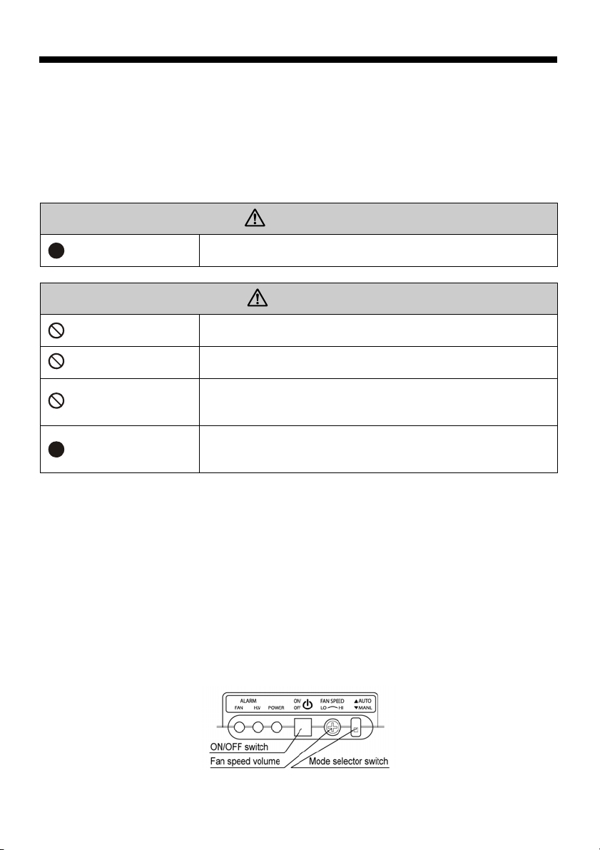
(1) Turn the operation mode selector switch to “▲ AUTO.”
(2) When the power is turned on, the power indicator lights up and automatic operation begins.
The fan turns and ions are generated.
Pause
(1) Pressing the power ON/OFF switch once during operation stops the supply of electricity and
pauses operation.
Stop
(1) Turning of the main unit power also turns off the static eraser at the same time.
23
Page 24
Operation
Manual operation
Start
(1) Turn the operation mode switch to “▼ MANL”.
(2) When the power is turned on, press the power ON/OFF switch once to cause the power
indicator to turn on and operation to start. The fan turns and ions are generated.
Stop
Pressing the power ON/OFF switch once during operation stops the supply of electricity and
stops operation. In addition, turning off the main unit power also turns off the static eraser at the
same time.
Blow volume adjustment
Turning the blow volume control to the left lowers the blow volume. Turning it to the right increases
the blow volume. Use the included screwdriver to make the adjustments.
CAUTION
The control adjustment rotation range is about 270°. Do not use excessive
Remember
“NEEDLE CLEAN “Warning Lamp”
Operation Lamp blinks every 100-hour use for IMMEDIATE CLEANING, periodical cleaning of needle
every 100-hour operation. (See Page. 32)
*Ionizing operation can be continued during the blinking.
*After the cleaning, please keep pressing ON/ OFF switch for more than 3 seconds, then resetting the
accumulative operation hours recorded and no blinking. (Accumulative running hours won’t be faded
nor resetting even if power supply suspended.)
Warning Indicator
(1) Abnormal high voltage warning indicator: This illuminates when the high-voltage output is
(2) Fan lock warning indicator: This illuminates when the fan motor stops turning.
When a warning indicator illuminates, unplug the product and check the following points.
(1) Is foreign matter adhered close to the discharge needle?
Æ Refer to maintenance for the “Static Eraser” item under “Maintenance.”
(2) Is foreign matter caught in the fan motor?
Æ After removing the cause, turn on the power again, and check if the warning indicator has
turned off.
*If the warning indicator illuminates again, have the unit repaired by the product was purchased.
*If the warning indicator has turned on, the static eraser’s power ON/OFF switch will not operate. Turn
the No. IPC40-E’s operation switch to stop (〇) and wait about 5 sec before turning it on again.
force when using the screwdriver to turn it. Using excessive force could break
the control.
abnormal.
24
Page 25
Operation
Sensors
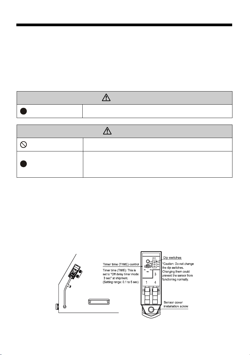
These are regression reflection beam sensors that are located on the right and left side of the work
hood opening. When the work is held by hand and placed in the hood, the sensors detect the work
and open the air solenoid valve.
*Sensor is set to “Off delay timer mode: approx. 3 sec” at shipment.
This mode continues output for just the time the set time is extended after the detection signal is off.
*The timer time is adjusted at shipment, but the included plastic adjustment tool can be used to make
fine adjustments.
WARNING
Unplug the power cord
To prevent electrical shock accidents, be sure to unplug the power
cord from the outlet before inspecting the static eraser.
CAUTION
Disassembly Prohibited
Remember
Do not modify or disassemble the product.
The sensitivity and timer are set at the time of shipment. Do not
change the settings unnecessarily. When making fine adjustments,
use the included sensor adjustment tool. When making adjustments,
turning the control with excessive force could damage it.
Timer setting method
The output time can be adjusted by adjusting the timer to extend the time after the detection signal is
off.
(1) Use the adjustment tool to loosen the sensor cover installation screws and then remove the sensor
cover.
(2) Use the included adjustment tool to make fine adjustments by turning the timer (TIME) control.
Turning left shortens the time and turning right lengthens the time.
(3) After making the adjustment, securely replace the sensor cover and tighten the sensor cover
installation screws.
25
Page 26
Operation
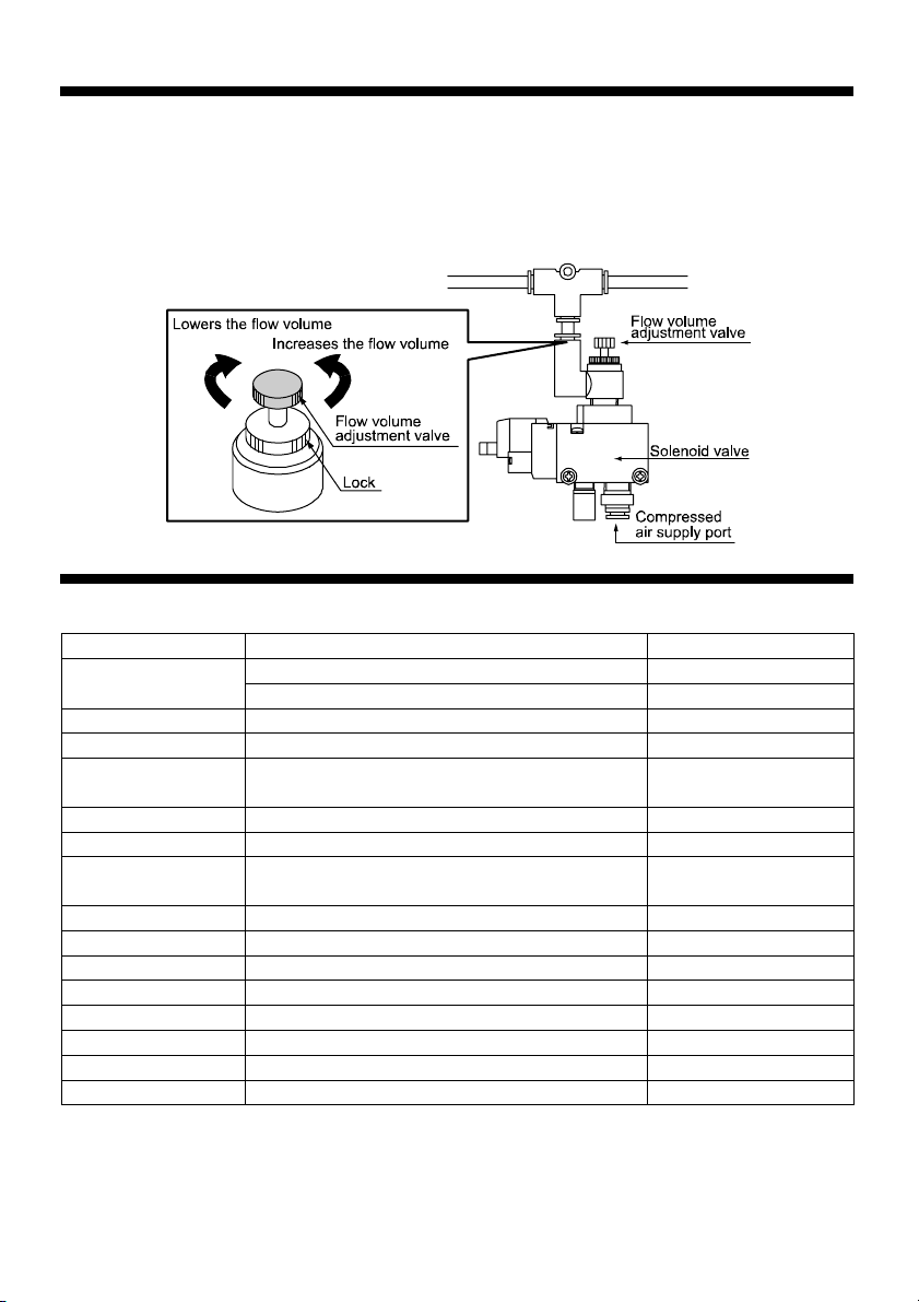
Compressed air flow volume adjustment valve
There is a “flow volume adjustment valve” on the secondary side of the “solenoid valve” located on
the rear of the unit.
The compressed air that is blown from the air nozzle can be adjusted to be stronger or weaker.
*This is set to the maximum blow volume at the time of shipment.
Maintenance
Pre-work Inspection
Inspection Location Inspection Description Measures
Main unit
Work hood Main unit wear, corrosion, and damage. Repair by manufacturer
Perforated plate Deformation or damage that interferes with work Replace
Clear acrylic sheet
Seal packing Air leaks or dust leaks in the main unit or duct piping Replace
Drawer tray Dust accumulation condition Dust disposal processing
Filter unit
Power plug Is it completely plugged into the outlet? Plug it in properly
Operation switch Damaged, missing, or malfunctioning Repair by manufacturer
Fan Abnormal vibration Repair by manufacturer
Bearing Making of abnormal sounds Repair by manufacturer
Sensor Is it operating normally? Repair by manufacturer
Solenoid valve Is it operating normally? Repair by manufacturer
Compressed air nozzle Is it operating normally? Repair by manufacturer
Static eraser Is it operating normally? Repair by manufacturer
Dust accumulation condition Dust disposal processing
Main unit wear, corrosion, and damage. Repair by manufacturer
Scratches, dirtiness, or damage that makes it difficult to
set the work area inside the hood
Filter body clogging, damage, deterioration, dampness,
etc., and deteriorated, damaged, or missing packing
Replace
Remove the dust or
replace the filter unit
26
Page 27
Maintenance
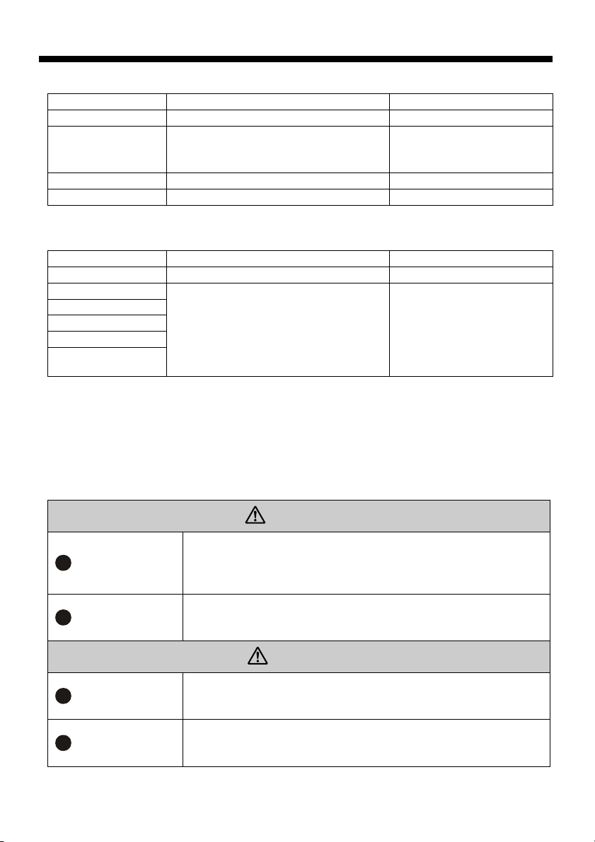
Post-work Inspection
Inspection Location Inspection Description Measures
Drawer tray Dust accumulation condition Dust disposal processing
Filter body clogging, damage, deterioration,
Filter unit
Main unit Dust accumulation condition Dust disposal processing
Motor Abnormal heat generation Repair by manufacturer
dampness, etc., and deteriorated, damaged, or
missing packing
Periodic Inspection Perform about once a month. This is performed by the manager.
Inspection Location Inspection Description Measures
Power cord (plug) Is there any deformation or scratches? Repair by manufacturer
Control box
Sensor
Solenoid valve
Compressed air nozzle
Static eraser
Are the installation screws or other components
loose or missing? Are parts damaged or
deteriorated?
Dust Removal and Disposal
If the vacuum force appears to have dropped during use, the internal filter unit is clogged, so use the
following procedure to remove the dust. When doing this, flammable dust could catch fire or explode
under certain conditions, so quickly dispose of the accumulated waste.
Remove the dust or replace the
filter unit
Be sure to turn off the switch and
unplug the power cord before
tightening or installing screws,
etc. Replace or have the
manufacturer repair damaged or
deteriorated parts.
Remember
Remember
Remember
Remember
WARNING
Quickly dispose of the dust without letting it accumulate.
Even if the dust is non-flammable, the dust could catch fire or explode
depending on the particle size, concentration, or other conditions, so
be careful when removing any kind of dust.
Since an unexpected problem could occur in the disposal of mixed
collected dust, we ask that the customer be responsible for making this
determination.
CAUTION
To prevent a fire accident, always check the dust after conducting work
that generates sparks, etc., and inspect the unit before concluding the
work for the day.
If the front cover is not attached properly, the vacuum force could drop
or overloading could cause the motor to burnout, so make sure the
cover is attached properly.
27
Page 28
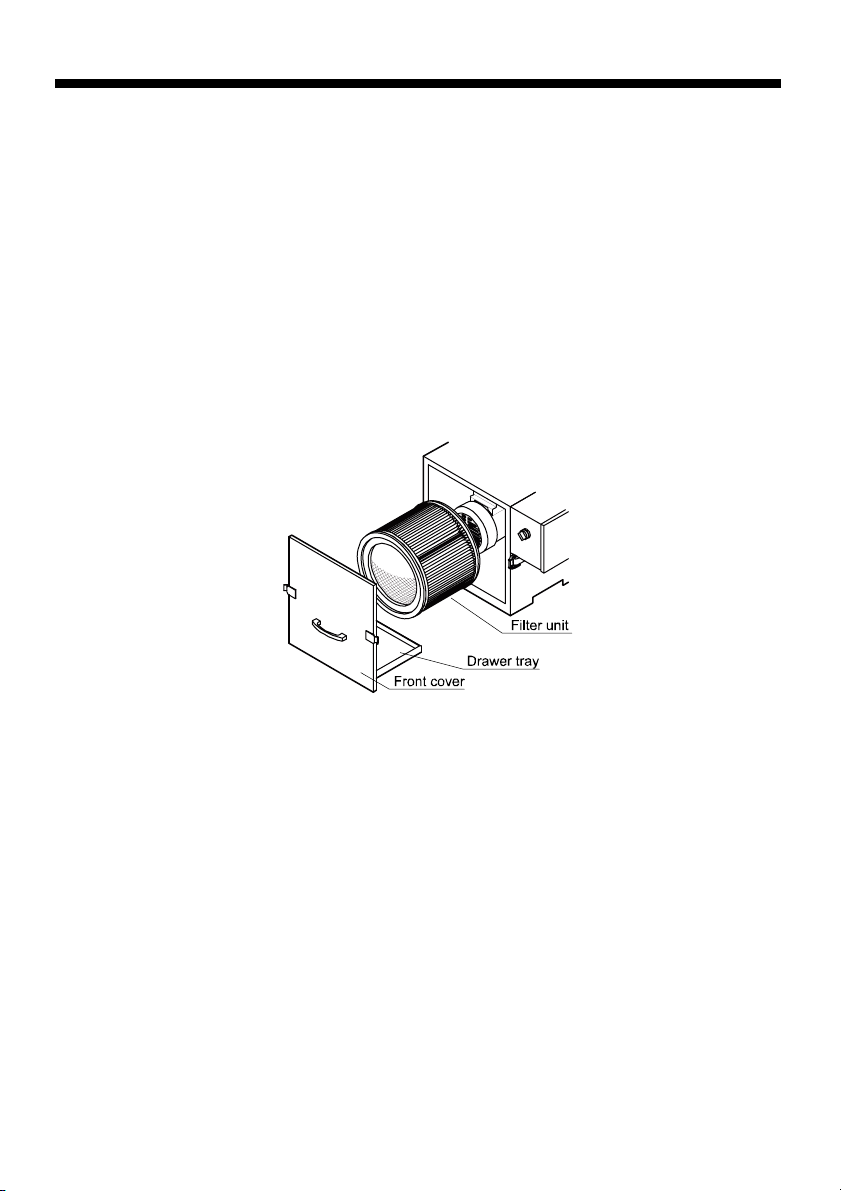
Maintenance
Cleaning the filter unit (Removing dust)
(1) Turn off the power Switch the main switch to OFF (○) to turn off the power and always confirm
that the fan has completely stopped rotating. Not doing so could stir up the
fine dust that has been collected.
(2) Open the front cover Unlock the thumb lock and take off the front cover.
(3) Remove the filter Remove the internal filter unit.
(4) Remove the dust Remove the filter unit dust.
(5) Dispose of the dust Dispose of the dust in the draw tray.
(6) Install the filter Install the filter unit back in its original location.
(7) Close the front cover Insert the front cover and completely close the thumb lock. If the front cover
is not properly installed, it could cause the vacuum force to drop or overload
the motor and cause it to burn out.
28
Page 29
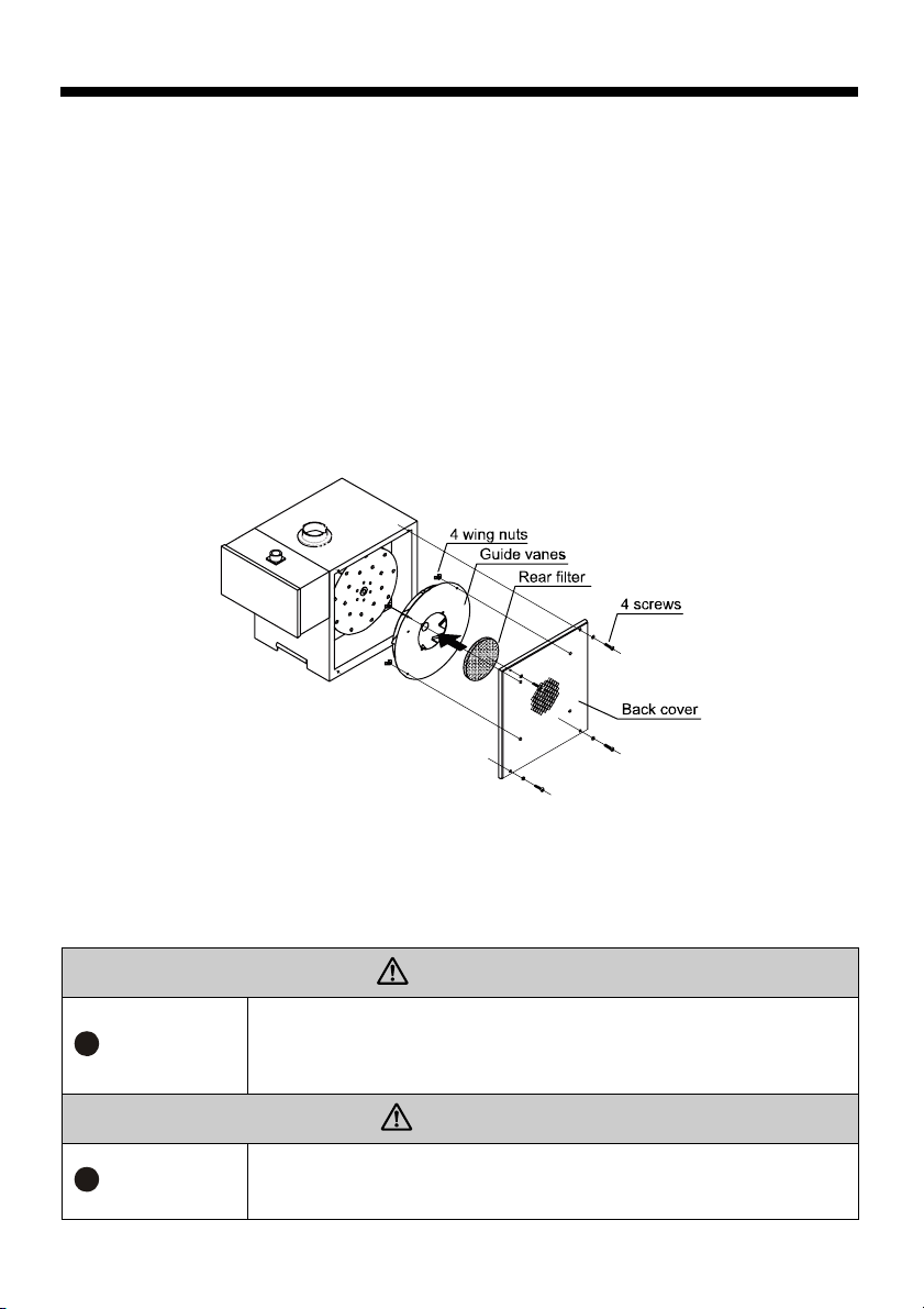
Maintenance
Cleaning the rear filter
The rear filter is located inside the rear cover. Clean it as required.
(1) Turn off the power. Switch the main switch to OFF (○) to turn off the power and always
(2) Loosen the screws. Loose the 4 screws on the rear cover and remove the rear cover.
(3) Loosen the wing nuts. Loosen the 4 wing nuts inside the rear cover.
Remove the rear filter. Remove the rear filter that is inserted into the guide vanes.
(4)
(5) Remove the dust.
(6) Clean up the dust.
Reinstall the rear filter. Reinsert the rear filter into the guide vanes.
(7)
Attach the guide vanes
(8)
to the rear cover.
(9) Close the rear cover. Tighten the 4 screws to attach the rear cover.
confirm that the fan has completely stopped rotating. Not doing so
could stir up the fine dust that has been collected.
Tighten the 4 wing nuts to attach the guide vanes to the rear cover.
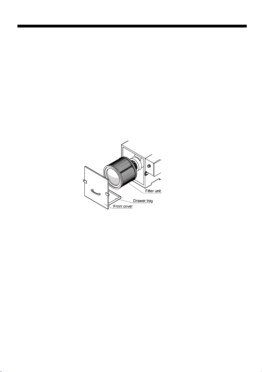
Filter Replacement
If the filter has become damaged or if after long use the vacuum force does not recover even after the
dust is removed, use the following procedure to replace the filter. (Filters can be purchased through
the product was purchased.)
WARNING
Make sure the fan has completely stopped rotating before replacing the
Remember
Remember
filter. In addition, sufficiently monitor the power so that the fan is not
accidentally turned on while the filter is being replaced. If the fan is on, it will
vacuum in things or blow them around, which could cause an accident.
CAUTION
If the front cover is not attached properly, the vacuum force could drop or
overloading could cause the motor to burnout, so make sure the cover is
attached properly.
29
Page 30
Maintenance
Cleaning the rear filter
The rear filter is located
inside the rear cover. Clean it
as required.(1) Turn off the
power.
(2) Loosen the screws.
(3)
Loosen the wing nuts.
(4) Remove the rear filter.
(5) Remove the dust.
(6) Clean up the dust.
(7) Reinstall the rear filter.
(8) Attach the guide vanes to
the rear cover.
(9) Close the rear cover.
Switch the main switch to OFF (○) to turn off the power and
always confirm that the fan has completely stopped rotating.
Not doing so could stir up the fine dust that has been collected.
Loose the 4 screws on the rear cover and remove the rear cover.
Loosen the 4 wing nuts inside the rear cover.
Remove the rear filter that is inserted into the guide vanes.
Reinsert the rear filter into the guide vanes.
Tighten the 4 wing nuts to attach the guide vanes to the rear cover.
Tighten the 4 screws to attach the rear cover.
30
Page 31
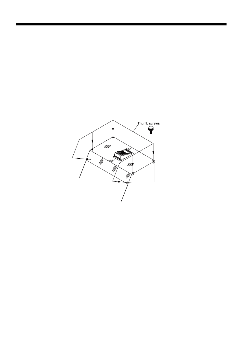
Maintenance
Clear Acrylic Sheet Replacement
If the clear acrylic sheet in the hood front or rear becomes scratched or dirty such that it makes it
difficult to see inside the hood, use the following procedure to replace the clear acrylic sheet.
(You can purchase it from the store where the product was purchased by specifying either the front
or rear clear acrylic sheet of IPC40-E.)
(1) Loosen the screws. Loosen the 6 thumbscrews.
(2) Remove the acrylic sheet. Remove the acrylic sheet.
(3) Attach the acrylic sheet. Attach the new acrylic sheet.
(4) Tighten the screws. Tighten the 6 thumbscrews.
The screw positions are shown in the figure below.
31
Page 32
Maintenance
Static Eraser Maintenance
The static eraser is nearly maintenance free, but occasionally clean the case, filter, and electrode
wires. Dirtiness or wearing around the electrode wires could cause a decline in static electricity
erasing capability. In addition, it is recommended that the ion balance be measured to check for a
drop in capacity.
WARNING
Unplug the power cord
Do not disassemble
Prohibited
Do not wet
Check
How to Clean the Electrode Wire
Clean the electrode wire about every 100 hours of use. To prevent electrical shock accidents, be sure
to unplug the power cord from the outlet and wait at least 1 min before cleaning the electrode wires.
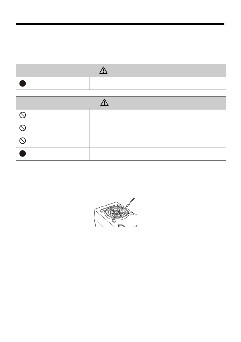
Insert a cotton swab into the clearance on the finger guard to clean the electrode wire. If the electrode
is heavily contaminated, clean it with a cotton swab with a little alcohol and remove the stuck dirt. Do
not rub the electrode wire hard for cleaning. Failure to do so can result in a bent wire. Wipe it lightly.
How to Replace the Electrode Wire
Do not replace the electrode wire with a new one by yourself. Contact the store where the product was
purchased.
Static Erasing Capacity Check
Measure ion balance and charge voltage-dampening time using a charge plate monitor.
Reference: IEC61340-5-1・2, ANSI EOS/ ESD S3.1
Adjustment
Because ions are generated with AC output, the SDJ-08S does not have an adjustment feature of ion
balancing. If ion balance is not good, contact the store where the product was purchased.
Cleaning the Case
Use a well-wrung, soft cloth soaked with water to clean the case. Do not use cleaners or other
substances containing surface-active agents as these could have a negative impact on the static
electricity erasing performance.
To prevent electrical shock accidents, be sure to unplug the
power cord from the outlet before inspecting the static eraser.
CAUTION
Do not remove the finger guard. Failure to do so can result in
electric shock and breakdown.
Do not wipe with detergent or solvent. Substances of the sort
can cause cracking and result in electric shock or breakdown.
Do not wet the IPC40-E. Contact with moisture can result in
electric shock or breakdown.
Periodically check the IPC40-E. Failure to perform checks can
result in early breakdown.
32
Page 33
Storage
Storage
CAUTION
Prohibited
Do not store the IP40-E in the below environments.
・Adverse environments can result in explosion, fire, electric shock and
accident.
・ Where explosion-proofing is required, where found flammable
atmospheres
・ Where excessive vibration or shock is applied to the eraser.
・ Where temperature and humidity are outside specified ranges.
・ Where dewing or sharp temperature fluctuations occurs.
・ Where there is heavy dust or smoke, where possibly wet by water, oil,
chemicals, etc.
・ Where strong electric or magnetic fields are generated.
Troubleshooting
Trouble Measures
Be sure to unplug the power cord from the outlet before looking for the cause of the trouble.
Request repairs at the store where the product was purchased.
Trouble Description Cause/ Inspection Measures
The specified performance
is not obtained
Motor does not turn
There is abnormal noise or
vibration
Dust is exhausted
Dust collecting capability
does not recover even after
servicing the filter unit
Sensor does not function Internal component is broken Repair by manufacturer
Solenoid valve does not
function
Static eraser does not
function
Power specifications do not match Match the rated specifications
Damaged or clogged filter unit Replace with a new component
Defective power connection Perform the wiring correctly
Use power voltage that is in a
Thermal protector has operated
Switch is broken Repair by manufacturer
Motor is burned out Repair by manufacturer
The impeller is not balanced properly. Repair by manufacturer
Bearing Repair by manufacturer
Damaged or clogged filter unit Replace with a new component
Inspect the seal packing
Filter unit installed improperly
Clogged filter unit Replace with a new component
Internal component is broken Repair by manufacturer
Control circuit is broken Repair by manufacturer
Internal component is broken Repair by manufacturer
33
range of ±10%
Make sure all covers are closed
completely to prevent air leaks
Inspect the seal condition and
replace if necessary
Set it in the proper position after
inspection
Page 34
Removal
Removal
When removing this product, first make sure the surrounding area and other workers are safe.
CAUTION
Unplug power cable
Remember
Remember
Remember
To prevent electrical shock accidents and operational mistake
accidents during the product removal work, be sure to unplug the
power cord from the outlet.
When disconnecting a compressed air hose, be sure to first shut off the
source of the compressed air. In addition, the compressed air inside
the air hose could spray out when the air hose is disconnected, so keep
the hose away from the face, etc., when disconnecting it.
To keep the unit from falling over, do not climb on the hood or dust
collector or place heavy objects on them.
Check the following, being aware of the weight of the product.
・ Be sufficiently careful that no part of the body, especially fingers and
toes, will be caught underneath the product while it is being removed
or moved.
・ Make sure the product does not fall over while it is being removed or
moved.
・ Do not move the product while an object is set on its hood. The
object could fall off of the hood.
Disposal
Disposal
When disposing of this product, dispose of it properly in accordance with the pertinent laws and
local regulations.
Replacement Parts
Replacement Parts
There are 3 consumable parts that can be replaced by the
customer.
Check the model and lot No. and then purchase the parts
through the store where the product was purchased.
○Filter unit part No. (22)
○Front clear acrylic sheet part No. (2)
○Rear filter part No. (25)
For information about the replacement procedure, refer to the “ Maintenance” item in this manual.
34
Page 35

LIMITED WARRANTY:
VESSEL expressly warrants that for a period of one (1) year from the date of purchase, VESSEL static
erasers will be free of defects in material (parts) and workmanship (labour). Within the warranty period,
Defects occurring will be repaired or products will be replaced at VESSEL's option and expense, if
VESSEL receives notice during the warranty period. Defective products must be
returned to VESSEL Osaka Japan with proof of purchase date. And if your unit is out of warranty,
VESSEL will quote repair charges necessary to ship your unit freight prepaid to where you have
originally purchased.
WARRANTY EXCLUSIONS:
THE FOREGOING EXPRESS WARRANTY IS MADE IN LIEU OF ALL OTHER PRODUCT
WARRANTIES, EXPRESSED AND IMPLIED, INCLUDING FITNESS AND MERCHANTABILITY AND
FITNESS FOR A PARTICULAR PURPOSE WHICH ARE SPECIFICALLY DISCLAIMED.
The express warranty will not apply to defects or damage due to accidents, neglect, misuse,
alterations, operator error, or failure to properly maintain, clean, or repair products.
LIMIT OF LIABILITY:
This electronic static eraser use high voltage corona discharge and should not be used in or near
flammable or explosive environments. In no event will VESSEL or any seller is responsible or liable for
any injury, loss or damage, direct or consequential, whether based in tort or contract arising out of the
use of or the inability to use the product. Fulfillment of VESSEL's warranty obligations will be
Customer's exclusive remedy and VESSEL's and Seller's limit of liability for any breach of warranty or
otherwise. Before using this unit, users shall determine the suitability of the product for their intended
use, and users assume all risk and liability whatsoever in connection therewith.
35
Page 36
CERTIFICATE OF INSPECTION
We hereby certify that before shipment, above tool has been carefully
inspected according to our factory engineering standard and the result has come out
in satisfactory data. In order to maintain the best conditions of this tool, please be
sure to take a few minutes to read through the enclosed instruction manuals and operate
as recommended.
DATE: CHIEF INSPECTOR:
SERIAL NO.
MANUFACTURED BY VESSEL CO., INC. OSAKA JAPAN
Manufactured by:
VESSEL CO., INC.
Higashinari-ku, Osaka 537-0001 Japan
Tel : +81 6 6976 7778 Fax : +81 6 6972 9441
E-mail : [email protected]
URL : http://www.vessel.jp
36
Printed in Japan
20070905
 Loading...