

Vess R2600fiD, R2600iD, R2600iS, J2600sD, J2600sS Quick Start Manual
...
1

Vess R2000
Series
Vess J2000
Series
Quick Start Guide Version 1.0
Contents
English … Page 001 ~ 021
Deutsch
… Page 022 ~ 042
Français
… Page 043 ~ 063
Italiano
… Page 064 ~ 084
Español
… Page 085 ~ 105
Русский
… Page 106 ~ 126
日本語
… Page 127 ~ 147
繁體中文
… Page 148 ~ 168
简体中文
… Page 169 ~ 189
한국어
… Page 190 ~ 210
PTVR2K
PTVJ2K
© 2012 PROMISE Technology, Inc. All Rights Reserved.

1
Warning
This is a Class A product. In a domestic environment this product
may cause radio interference in which case the user may be
required to take adequate measures.
Warning
The electronic components within the Vess R2600 or Vess J2600
enclosure are sensitive to damage from Electro-Static Discharge
(ESD). Observe appropriate precautions at all times when
handling the Vess R2600 or its subassemblies.
Caution
* There is a risk of explosion if the battery is replaced by the
incorrect type.
* Dispose of used batteries according to the instructions that
accompany the battery.

2
Contents
VESS R2600 TASK LIST ......................................................................4
TASK 1: UNPACKING ..........................................................................4
VESS R2600 PACKING LIST........................................................4
VESS J2600 PACKING LIST ........................................................4
VESS R2000 SERIES MODEL LINE-UP.........................................4
VESS J2000 SERIES MODEL LINE-UP..........................................4
TASK 2: MOUNTING Vess R2600 IN A RACK....................................6
TASK 3: INSTALLING DISK DRIVES ..................................................9
DRIVE SLOT NUMBERING .............................................................9
INSTALLING YOUR DISK DRIVES.................................................9
NUMBER OF DRIVES REQUIRED................................................10
TASK 4: MANAGEMENT CONNECTIONS ........................................10
MANAGEMENT PATH NETWORK (ETHERNET)
CONNECTION .............................................................................10
MANAGEMENT PATH SERIAL CONNECTION.........................11
SAS JBOD EXPANSION ...............................................................12
CONFIGURING THE DATA PATH..............................................12
CONFIGURING A MANAGEMENT PATH..................................12
SAS JBOD EXPANSION.............................................................12
TASK 5: CONNECTING THE POWER..........................................13
FRONT PANEL LEDS .................................................................14
REAR PANEL PSU & COOLING FAN LEDS.............................15
CONTROLLER LEDS ....................................................................15
DISK DRIVE LEDS ......................................................................15
TASK 6: SETTING THE IP ADDRESS..........................................16
CHOOSING DHCP OR A STATIC IP ADDRESS .......................16
Setting up with the CLU ...............................................................16
SETTING SYSTEM DATE AND TIME.........................................16
MAKING MANUAL IP SETTINGS...............................................16

3
MAKING AUTOMATIC IP SETTINGS.........................................17
CONFIGURING THE RAID..........................................................17
VIEWING IP ADDRESS AND SETTINGS...................................17
EXITING THE CLU ......................................................................17
TASK 7: CREATING LOGICAL DRIVES WITH WEBPAM
PROE..............................................................................................17
LOGGING INTO WEBPAM PROE..............................................17
INITIAL CONNECTION................................................................17
SECURE CONNECTION .............................................................17
CHOOSING A LANGUAGE ................................................................18
CREATING YOUR LOGICAL DRIVES..........................................18
USING WEBPAM PROE OVER THE INTERNET.......................20
CONTACTING TECHNICAL SUPPORT........................................20
TECHNICAL SUPPORT SERVICES .............................................21
4
VESS R2600 TASK LIST
• Task 1: Unpacking the Vess R2600/ Vess J2600
• Task 2: Mounting Vess R2600/ Vess J2600 in a Rack
• Task 3: Installing Disk Drives
• Task 4: Management Connections
• Task 5: Setting Up Serial Cable Connections
• Task 6: Connecting the Power
• Task 7: Setting the IP Address
• Task 8: Creating Logical Drives with WebPAM PROe
• Contacting Technical Support
TASK 1: UNPACKING
Note
The Vess R2000 series and Vess J2600 can accommodate SAS and SATA (3Gbps/6Gbps) hard drives. SATA drives
require an additional adapter that is installed before shipping. Make sure you have the correct drive carriers for the
hard drives that will be installed. Talk to your vendor for more information. Also see pictures of the different drive
carriers in “Task 3: Installing Disk Drives”.
VESS R2600 PACKING LIST
The Vess R2600 box contains the following items:
• Vess R2600 Unit (PTVR2K)
• Quick Start Guide printed
• RJ11-to-DB9 serial data cable
• Screws for disk drives (70 pieces for 16-bay)
• 1.5m (4.9 ft) Power cords (3 cords for 3 PSU installed,
4 cords for 4 PSU installed)
• CD with SNMP files, Product Manual and Quick Start
Guide in PDF format
• Sliding rail assembly for rack mounting
VESS J2600 PACKING LIST
The Vess J2600 box contains the following items:
• Vess J2600 Unit (PTVJ2K)
• Quick Start Guide printed
• RJ11-to-DB9 serial data cable
• Screws for disk drives (70 pieces for 16-bay)
• Sliding rail assembly for rack mounting
• 1.5m (4.9 ft) Power cords (3 cords for 3 PSU installed,
4 cords for 4 PSU installed)
• SAS cable (1 cable J2600sS/ 2 cables J2600sD)
• CD with SNMP files, Product Manual and Quick Start
Guide in PDF format
VESS R2000 SERIES MODEL LINE-UP
Model
Controller
Units
Interface
Number of
Drives
Power
Supplies
Cooling
Units
R2600fiD 2 FC/iSCSI 16 3 2
R2600iD 2 iSCSI 16 3 2
R2600fiS 1 FC/iSCSI 16 3 2
R2600iS 1 iSCSI 16 3 2
VESS J2000 SERIES MODEL LINE-UP
Model
Controller
Units
Interface
Number of
Drives
Power
Supplies
Cooling
Units
J2600sD 2 SAS 16 3 2
J2600sS 1 SAS 16 3 2
5
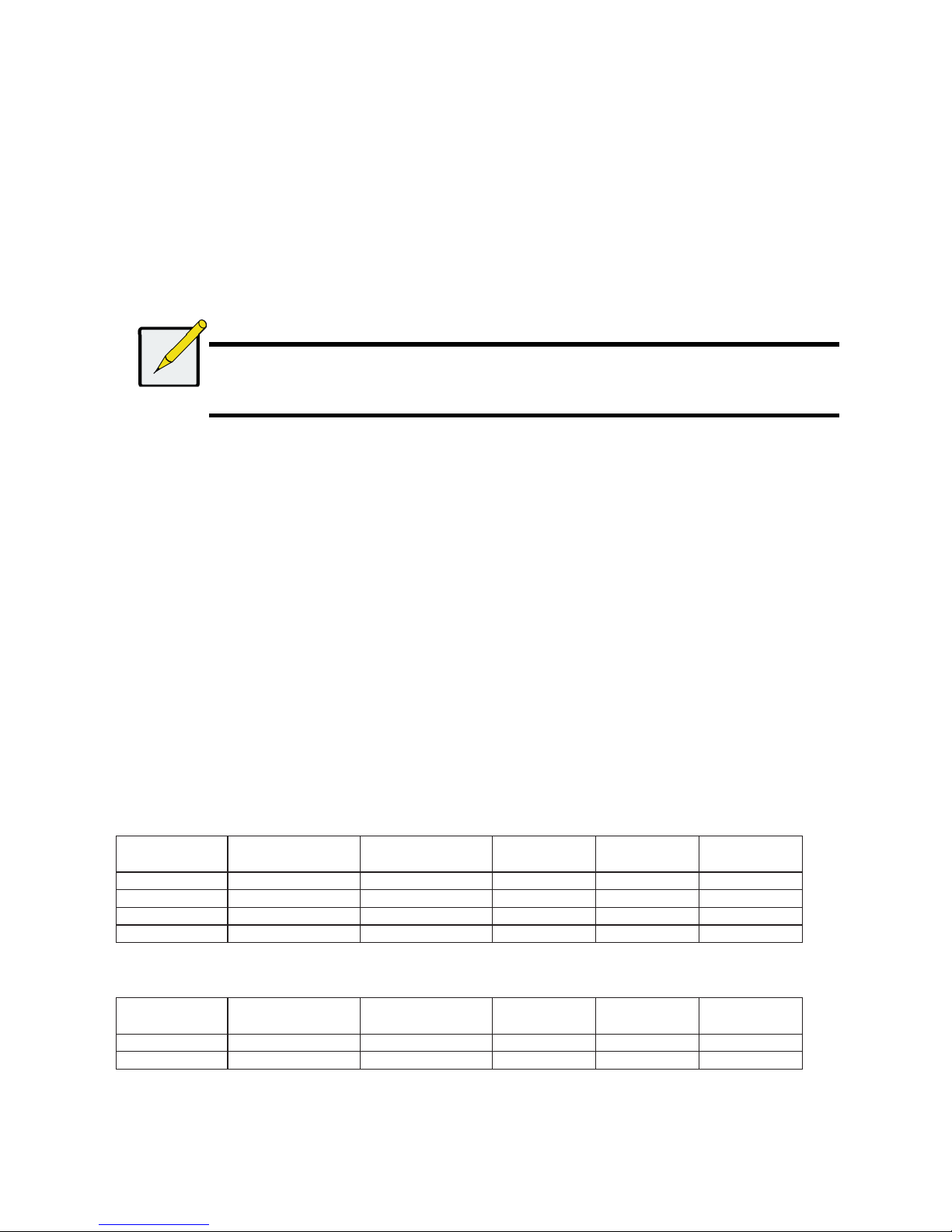
Figure 1: Vess R2600 front view
A defective drive may be replaced without interruption of data availability to the host computer. If so configured, a hot spare drive will
automatically replace a failed drive, securing the fault-tolerant integrity of the logical drive. The self-contained hardware- based RAID
logical drive provides maximum performance in a compact external enclosure.
Figure 2: Vess J2600 front view
Note
The Alarm Mute button, the LEDs and USB ports on the front of the left handle of the Vess J2600 are nonfunctional.
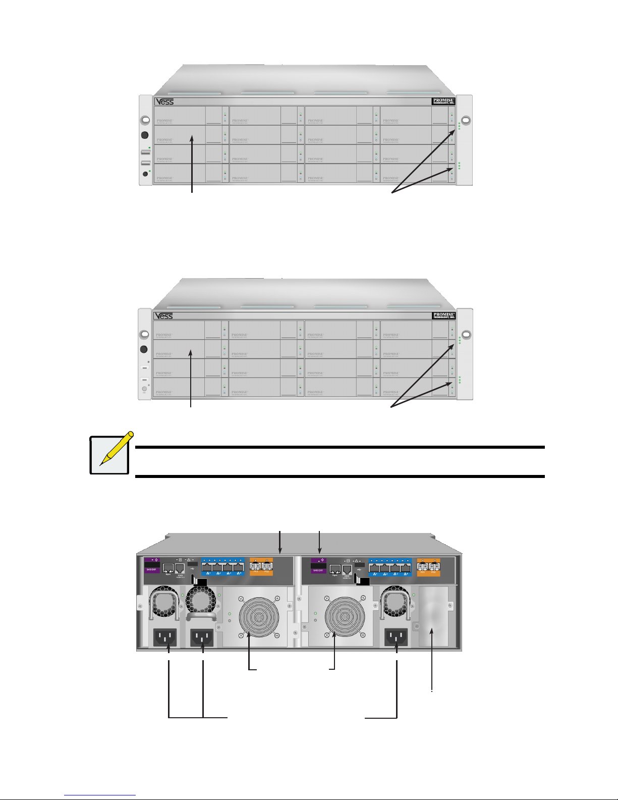
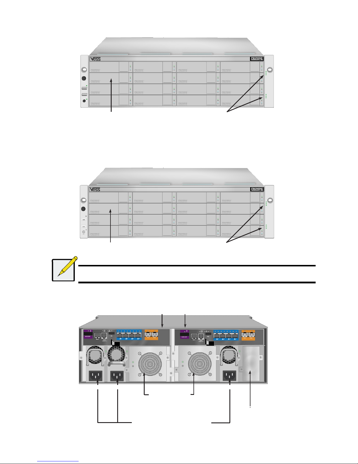
Figure 3: Vess R2600fiD rear view
Drive carriers Power and Status LEDs
Drive carriers
Power and Status LEDs
Controller modules
Unit 1 Unit 2
PSU 1 PSU 2
Cooling units
PSU 3
Unit 1
with battery
Unit 2
with battery
Powe
r
supplies
(Vess J2600 and Vess R2000 Series are
shipped with 3 power supplies installed.)
Empty bay for
optional fourth
power supply
6
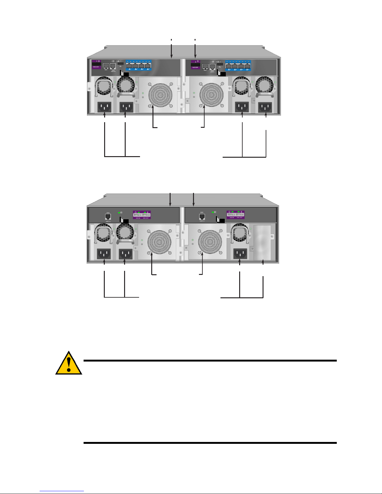
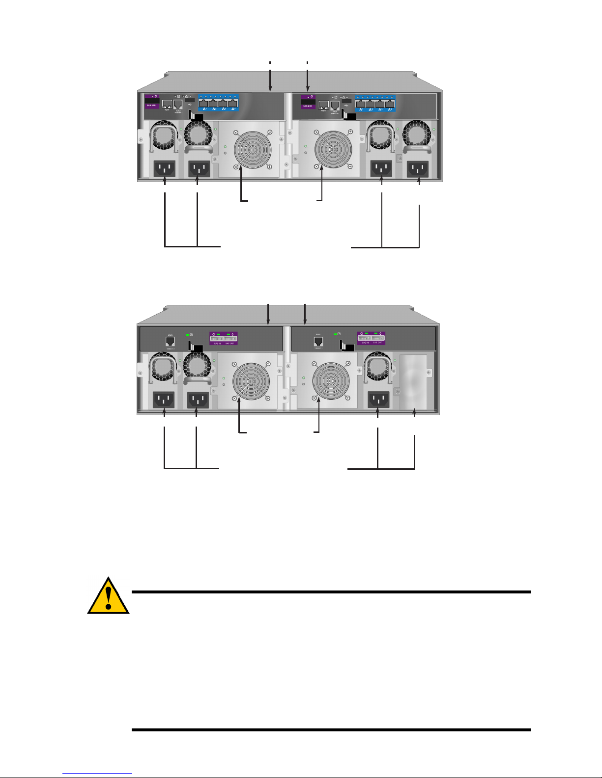
Figure 4: Vess R2600iD rear view
Figure 5: Vess J2600sD with optional four power supplies - rear
view
TASK 2: MOUNTING Vess R2600 IN A RACK
The instructions here apply to the Vess R2600 and Vess J2600 series.
Caution
* Do not populate any unit with hard drives until it has been securely installed in the rack.
* At least two persons are required to safely lift, place, and attach the Vess R2600 or Vess J2600 unit into a rack system.
* Do not lift or move the Vess R2600 or Vess J2600 unit by the handles, power supplies or the controller units. Hold the
subsystem itself.
* Do not install the Vess R2600 or Vess J2600 unit into a rack without rails to support the subsystem.
* Only a qualified technician who is familiar with the installation procedure should mount and install the Vess R2600 or Vess
J2600 unit.
* Mount the rails to the rack using the appropriate screws and flange nuts, fully tightened, at each end of the rail.
* Do not load the rails unless they are installed with screws as instructed.
* The rails available for the PROMISE Vess R2600 or Vess J2600 unit are designed to safely support that PROMISE Vess
R2600 or Vess J2600 unit when properly installed. Additional loading on the rails is at the customer’s risk.
* PROMISE Technology, Inc. cannot guarantee that the mounting rails will support your PROMISE Vess R2600 or Vess
J2600 unit unless you install them as instructed.
Optional
PSU 4
Controller modules
Unit 1 Unit 2
PSU 1 PSU 2
Cooling units
PSU 3
Unit 1
with battery
Unit 2
with battery
Powe
r
supplies
(Vess J2600 and Vess R2000 series are
shipped with 3 power supplies installed.)
Optional
PSU 4
Controller modules
Unit 1 Unit 2
PSU 1 PSU 2
Cooling units
PSU 3
Unit 1
Unit 2
Powe
r
supplies
(Vess J2600 and Vess R2000 series are
shipped with 3 power supplies installed.)
7
The Vess R2600 or Vess J2600 installs to the rack using the mounting rails shipped with the device.
Note
To lighten the Vess R2600 or Vess J2600 enclosure, you can remove the power supplies. Replace the power
supplies after the Vess R2600 or Vess J2600 unit is mounted in your rack.
To install the Vess R2600 subsystem or Vess J2600 expansion into a rack with the supplied mounting rails:
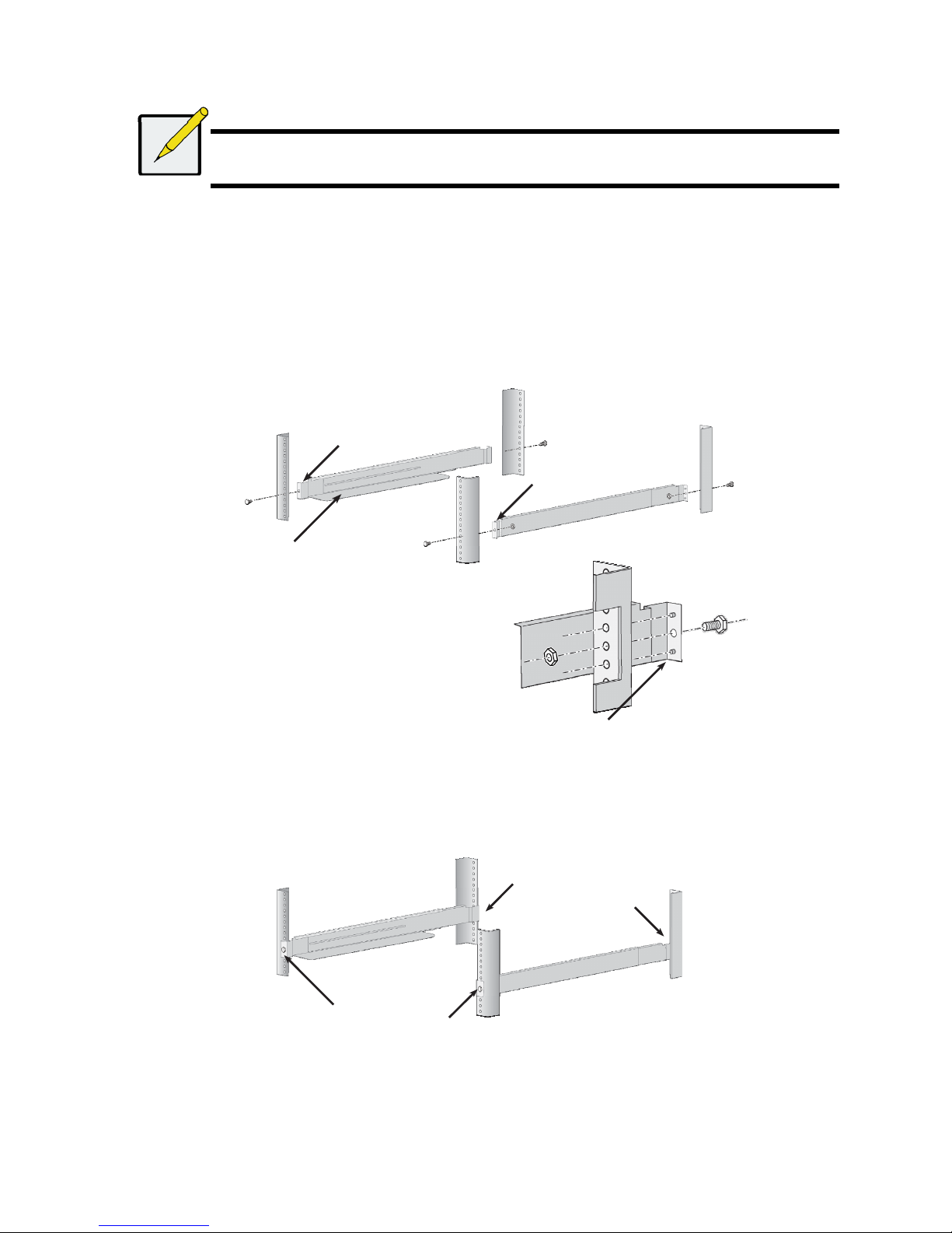
1. Check the fit of the mounting rails in your rack system.
2. Adjust the length of the mounting rails as needed.
• The rear rail slides inside the front rail. The rail halves are riveted together and use no adjustment screws.
• The front-left and front-right mounting rail ends are labeled.
• Be sure the front rail support is on the bottom facing inward.
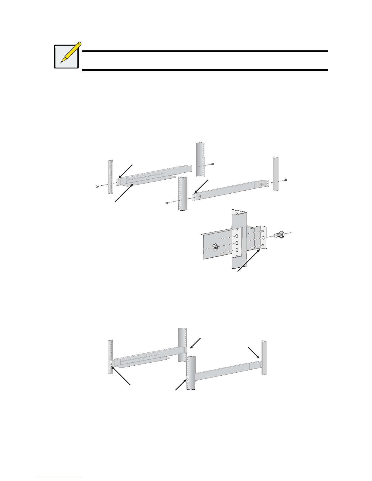
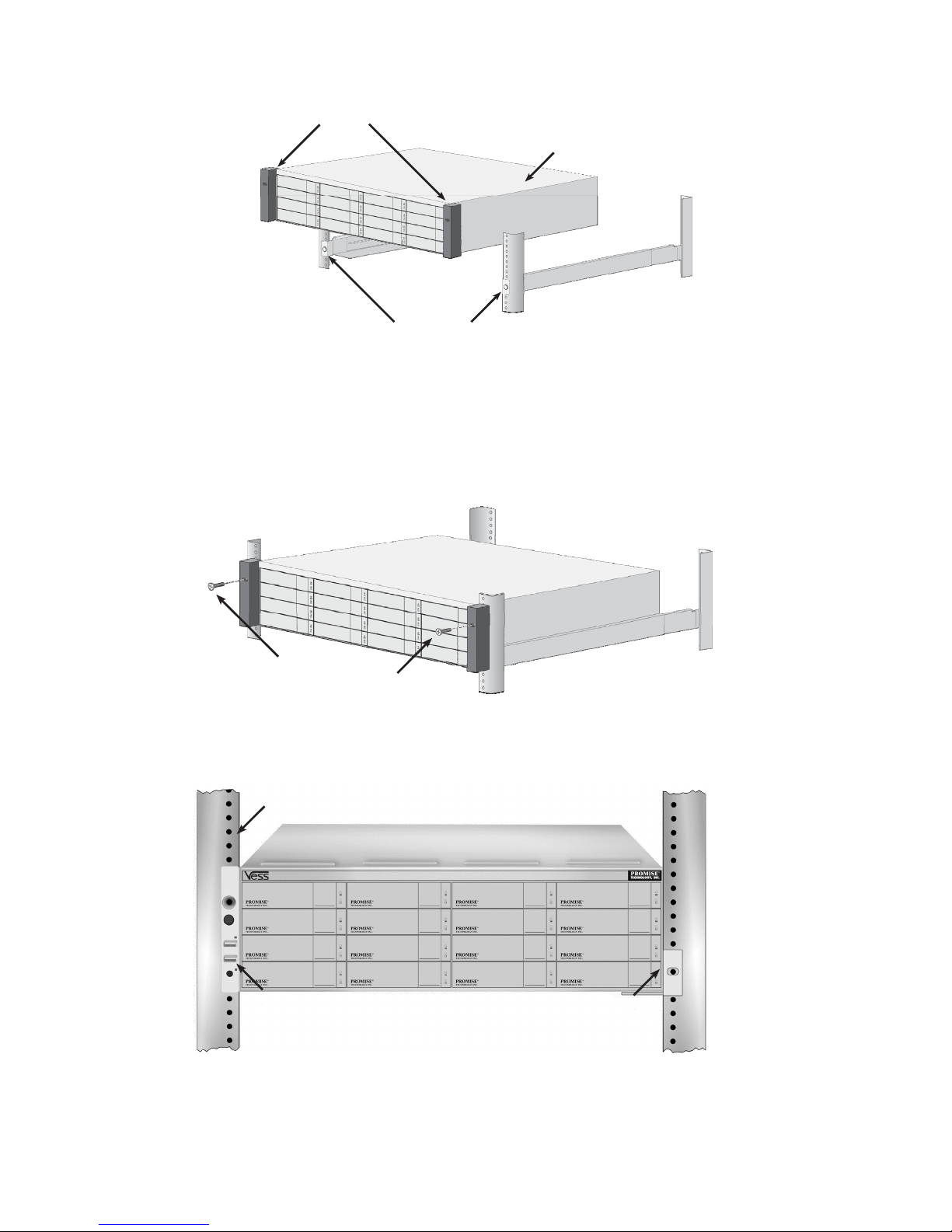
Figure 6: Installing the rails onto the rack
• All rail ends, front and rear, attach at the outside of the rack posts.
• The guide pins at the rail ends align with the holes in the rack posts.
• Use the attaching screws and flange nuts from your rack system. Tighten the screws and nuts according to instructions for
your rack
system.
Figure 7: Rail ends attach to the outside of each post
3. Place the Vess R2600 or Vess J2600 onto the rails.
• At least two persons are required to safely lift the subsystem.
• Lift the Vess R2600 or Vess J2600 itself. Do not lift the subsystem by its brackets.
Front left label
Front right label
Support flange on the
front
end of each rail
Guide pins on rails align with
holes in the rack post
Rail ends attach on the
outside of the front and
rear rack posts
8
Figure 8: Placing the subsystem onto the rack rails
4. Secure the Vess R2600 or Vess J2600 to the rack.
• The unit attaches to the rack posts using the included screws and flange nuts.
One screw each side, in the upper hole only.
• Use the attaching screws and flange nuts that came with the Vess R2600 or Vess J2600.
Figure 9: Secure to rack
Figure 10: Subsystem installed in rack
Brackets
Vess R2600 (or Vess J2600)
subsystem
Rails installed and
tightened
Screws and flange nuts
attach the Vess R2600
to the rack posts
Vertical rack post
Handles mount outside
the rack post
Mounting rails
mount outside the
rack post
9
TASK 3: INSTALLING DISK DRIVES
The Vess R2600 subsystems and Vess J2600 expansion units support:
• SAS hard disk drives
• SATA hard disks (requires additional factory installed adapter see Figures 14 and 15 below)
• 3.5-inch hard disk drives
For a list of supported physical drives, download the latest compatibility list from the PROMISE support website.
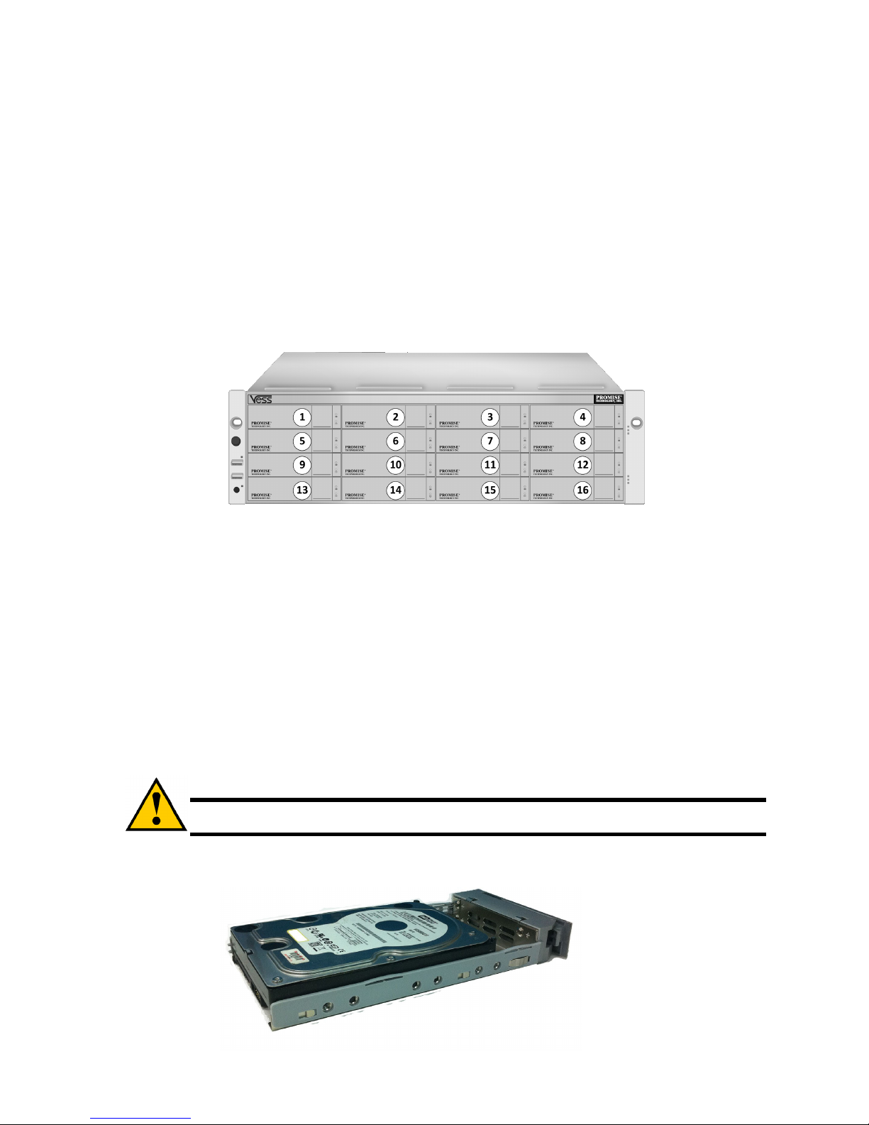
DRIVE SLOT NUMBERING
You can install any suitable disk drive into any slot in the enclosure. The diagram below shows how drive slots are numbered on both the
Vess R2600 and Vess J2600.
Slot numbering is reflected in the WebPAM PROe and CLU user interfaces.
Figure 11: 16-bay Drive slot numbering (Vess R2600 and Vess J2600)
Install all of the drive carriers into the enclosure to ensure proper airflow, even if you do not populate all the carriers with disk drives.
INSTALLING YOUR DISK DRIVES
The instructions below apply to all types of drive carriers intended for use with the Vess R2600 or Vess J2600. Note that SATA drives
require additional factory installed hardware. If you intend to use SATA hard drives, make sure the drive carriers shipped with the unit
are appropriate for your SATA drive. See Figures 13 and 14 for examples of drive carriers for SATA hard drives.
1. Remove a disk drive carrier.
2. Carefully lay the disk drive into the drive carrier at the front, so that the screw holes on the sides line up.
3. Insert the screws through the holes in the drive carrier and into the sides of the disk drive.
Install only the counter-sink screws supplied with the Vess J2600.
• Install four screws per drive.
• Snug each screw. Be careful not to over-tighten.
4. Reinstall the drive carrier into the Vess J2600 enclosure.
Repeat steps 1 through 3 until all of your disk drives are installed.
Caution
The Vess R2600 and Vess J2600 support disk drive hot-swapping. To avoid hand contact with an electrical
hazard, do not remove more than one drive carrier a time.
Figure 12: SAS disk drive mounted in a drive carrier
10
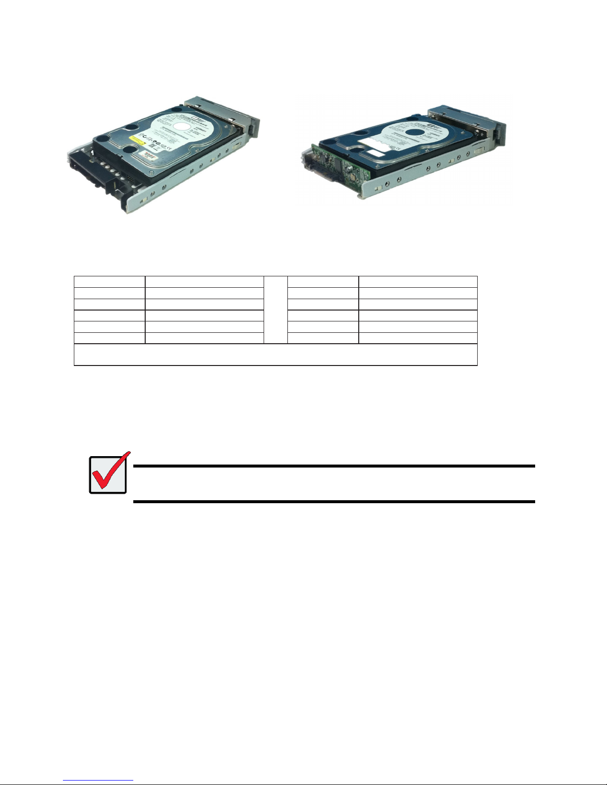
Use the Blackjack adapter for SATA 6Gbs drives and the AAMUX adapter for 3 Gbs SATA drives.
Figure 13: SATA disk drive mounted in carrier with Blackjack
adapter
Figure 14: SATA disk drive mounted in carrier with AAMUX
adapter
NUMBER OF DRIVES REQUIRED
The table below shows the number of drives required for each RAID level
Level Number of Drives Level Number of Drives
RAID 0 1 or more RAID 6 4 to 32*
RAID 1 2 only RAID 10 4 or more**
RAID 1E 2 or more RAID 30 6 or more
RAID 3 3 to 32* RAID 50 6 or more
RAID 5 3 to 32*
RAID 60 8 or more
* A JBOD expansion unit may be required.
** Must be an even number of drives.
TASK 4: MANAGEMENT CONNECTIONS
This section describes how to establish a management connection the Vess R2600 subsystem. There are two methods to establish a
management connection to the Vess R2600. The Vess J2600 system is managed through a Vess R2600 subsystem that is attached via
the SAS expansion link.
Important
For a list of supported FC HBAs, Switches and SFPs, download the latest compatibility list from the PROMISE support
website: http://www.promise.com/support/
Vess R2600 does not support cascading of multiple RAID
subsystems. Cascading is planned for a future release.
MANAGEMENT PATH NETWORK (ETHERNET) CONNECTION
The Vess R2600 controller has one (1) Ethernet RJ-45 Management Port connector. See “Figure 15: Vess R2600fi controller data and
management ports”.
To establish the management path:
1. Attach one end of an Ethernet cable to the network connector or standard NIC in the Host PC.
Attach the other end of the Ethernet cable to one of the ports on the standard network switch.
2. Attach one end of an Ethernet cable to one of the ports on the standard net- work switch.
Attach the other end of the Ethernet cable to the Management Port on the Vess R2600 subsystem.
If you have multiple Vess R2600 subsystems, Host PCs or Servers, repeat steps 1 and 2 as required.
11
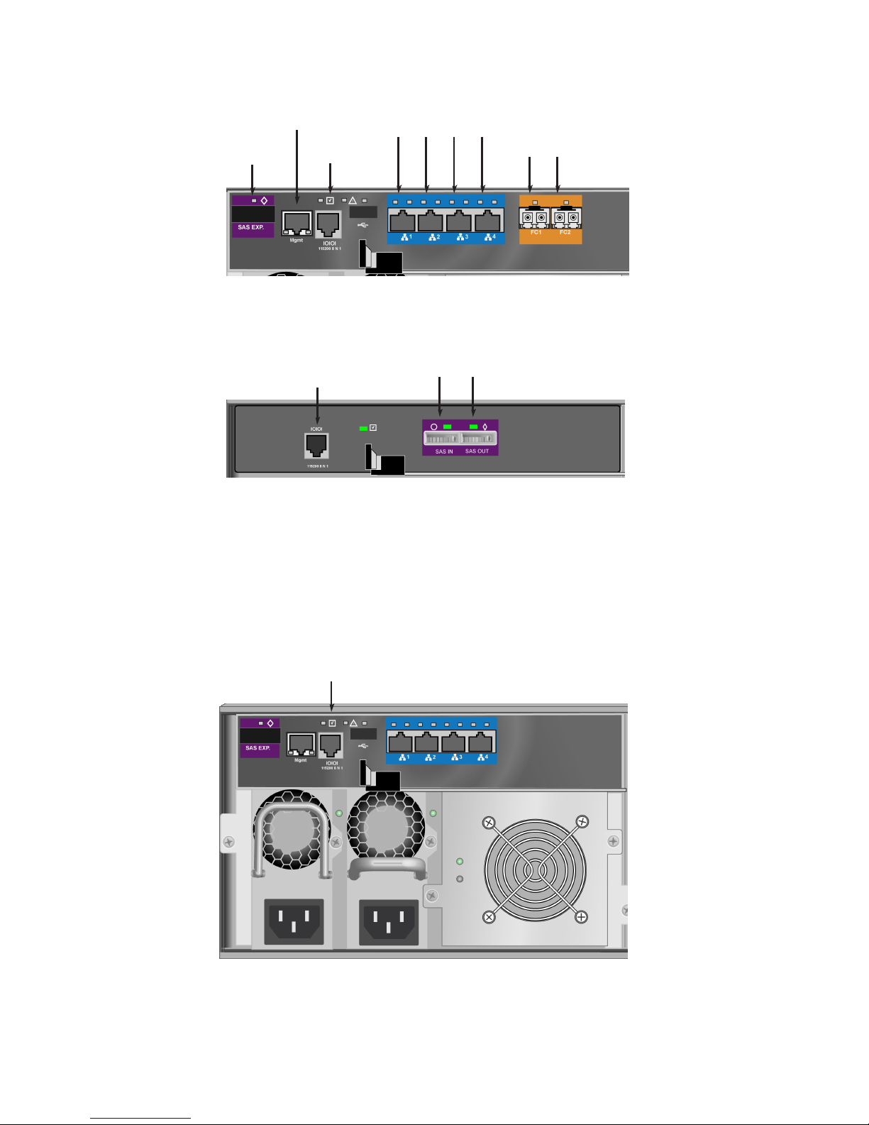
Figure 15: Vess R2600fi controller data and management ports
Figure 16: Vess J2600s controller management and data ports
MANAGEMENT PATH SERIAL CONNECTION
VessRAID has a Command Line Interface (CLI) to manage all of its functions. A subset of the CLI is the Command Line Utility (CLU), a
user-level interface that manages your Vess R2600 via your PC’s terminal emulation program, such as Microsoft HyperTerminal.
Serial communication enables the terminal emulation application on your host PC or server to access the Vess R2600 Command Line
Interface (CLI) to set up a network connection. The Vess R2600 package includes one RJ11-to-DB9 serial data cable for each controller.
Figure 17: Serial connector
To set up a serial cable connection:
1. Attach the RJ11 end of the serial data cable to the RJ11 serial connector on one of the RAID controllers.
2. Attach the DB9 end of the serial data cable to a serial port on the host PC or server.
SAS
expansion port
Network
mgmt port
Console
mgmt port
iSCSI data ports
1 2 3 4
FC data ports
1 2
Console mgmt port
(used for diagnostics, JBODs are
managed through a Vess R2600 unit
connected via SAS expansion)
SAS data ports
1 2
Serial port (RJ-11)
12
SAS JBOD EXPANSION
This arrangement requires:
• One (1) or more Vess J2600 expansion subsystems
• One (1) SFF-8088 to SFF-8088 SAS cable for each Vess J2600 expansion subsystem
CONFIGURING THE DATA PATH
VessRAID subsystems have one per RAID controller (1) SFF-8088 SAS Expansion Port connector.
To expand the data path:
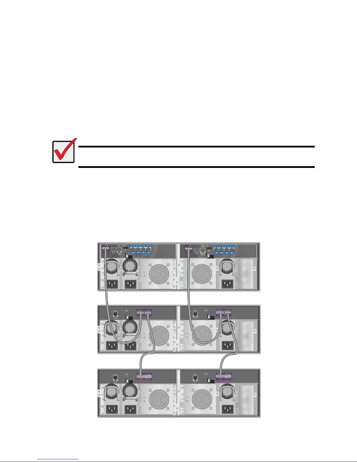
1. Attach one end of a SFF-8088 to SFF-8088 SAS cable to the SAS Expansion Port on the Vess R2600 subsystem.
See “Figure 20: SAS JBOD expansion data connections”.
2. Attach the other end of the SFF-8088 to SFF-8088 SAS cable to the SAS IN Port on the Vess J2600 subsystem.
If you have another Vess J2600 subsystem, attach one end of the SFF-8088 to SFF-8088 SAS cable to the SAS OUT Port of
the first Vess J2600 to the SAS IN Port of the second Vess J2600.
Important
Vess J2600 subsystems have one SAS IN port and one SAS OUT port. If you connect them incorrectly, the Vess
R2600 does not recognize the Vess J2600 subsystems.
For more information, see the Vess J2600 Product Manual on the CD that came with the Vess J2600 subsystem.
CONFIGURING A MANAGEMENT PATH
The Vess R2600 controller manages the Vess J2600 subsystems. No additional management connections are required for JBOD
expansion.
SAS JBOD EXPANSION
Figure 18: SAS JBOD
expansion
data
connections
13
TASK 5: CONNECTING THE POWER
Plug in the power cables on all power supplies.
Important
If you have a SAN, DAS, or Cascade with JBOD Expansion, always power on the JBOD subsystems first.
The Vess R2600 and Vess J2600 enclosures can be equipped with up to four power supplies for each unit. A minimum of two operating
power supplies are required for normal function of both the Vess R2600 and Vess J2600. The standard shipment includes three power
supplies. Contact your vendor for information on additional power supplies.
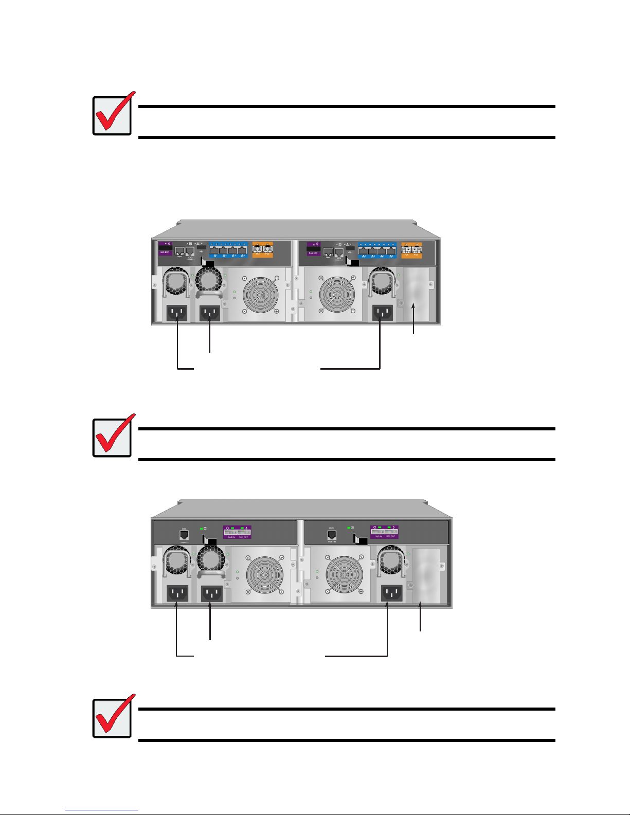
Figure 19: Vess R2600fiD rear panel power connections
Important
For information about installing or hot swapping power supplies, please see the product manual.
Figure 20: Vess J2600sD
Important
The Vess R2600 and Vess J2600 are equipped with LED indicators on the cooling units and power supplies. Check
these after powering the devices on to make sure the cooling and power status for the enclosure is normal.
PSU1, PSU2 and PSU3 are installed on
both the Vess R2600 and Vess J2600.
Connect all power supplies to a suitable
power source.
An
optional fourth powe
r
supply
(PSU4) can be installed in this bay.
See the product manual for more in
formation on installing and
swapping power supplies.
PSU1, PSU2 and PSU3 are installed on
both the Vess R2600 and Vess J2600.
Connect all power supplies to a suitable
power source.
An
optional fourth powe
r
supply
(PSU4) is available.
14
With the power supplies connected, the system can now be powered on. Again, note that if your setup includes a SAN, DAS or cascade
with Vess J2600 expansion, always power on the JBOD subsystems first.
To power on the subsystem, press the Power button on the front left bracket facing (see “Figure 21: Vess R2600 front panel components,
left side”). Observe the LEDs on the right front bracket facing (see “Figure 22: Vess R2600 front panel LED display on right side
bracket”).
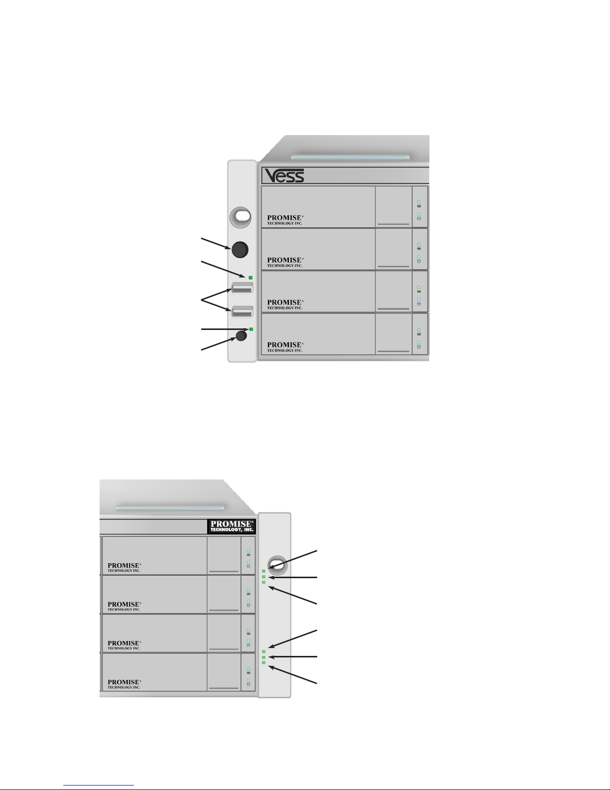
Figure 21: Vess R2600 front panel components, left side
FRONT PANEL LEDS
When boot-up is finished and the Vess R2600 subsystem is functioning normally:
• Power LEDs display blue continuously.
• Global Enclosure Status, and Global RAID Status LEDs display green continuously.
• Controller Activity LED flashes blue when there is controller activity.
• System Heartbeat LED blinks blue seven times in three seconds, goes dark for six seconds, then repeats the pattern.
Figure 22: Vess R2600 front panel LED display on right side bracket
Power button
OPAS LED
USB ports
Mute alarm LED
Mute alarm button
Power
Global Enclosure Status
Global RAID Status
Controller 1 Activity
Controller 2 Activity
System Heartbeat
15
REAR PANEL PSU & COOLING FAN LEDS
The LEDs on the rear panel include LEDs on each cooling fan and each power supply. These LEDs will light green to indicate normal
operation. A red or amber LED indicates a problem or unit failure. See the Product Manual for a complete description of LED indicators.
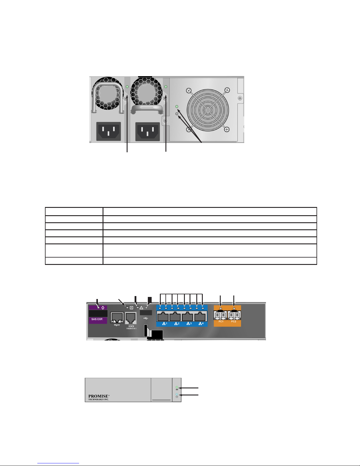
Figure 23: LEDs on Power Supply and Cooling Units
CONTROLLER LEDS
When boot-up is finished and the Vess R2600 subsystem is functioning normally, the Controller status LED displays green continuously;
the Management port LEDs display green or flash depending on your network connection; the FC, iSCSI, and SAS Expansion LEDs
display green or flash during port activity.
LED Description (refer to product manual for more details)
SAS Expansion Lights green when connected, flashes green when active.
Controller Status Green light indicates controller is operational.
Dirty Cache Lights amber if cache is dirty, otherwise dark.
USB Green light indicates a connection, dark when not connected.
iSCSI (2 above each port) Left LED lights green when connected, flashes green when active, dark if not connected. Right LED
indicates connection speed, green is 100 Mbps, amber is 1000 Mbps.
FC ports See product manual.
Figure 24: Vess R2600fi controller LEDs
DISK DRIVE LEDS
There are two LEDs on each Drive Carrier. They report the presence of a disk drive, activity of the drive, and the drive’s current condition.
Figure 25: Vess R2600 drive carrier LEDs
If there is a disk drive in the carrier, the Power/Activity LED displays Blue. If not, the Power/Activity LED remains dark. The
Power/Activity LED flashes Blue during drive activity.
The Disk Status LED displays Green when a drive is configured.
PSU 1 LED PSU 2 LED
Cooling Unit 1 LEDs
BBU (top)
Cooling Unit Fan Status (bottom)
SAS
Expansion
LED
Dirty
Cache
LED
Controlle
r
Status
USB
LED
iSCSI port LEDs
FC Port LEDs
Drive Status
Power/Activity
16
TASK 6: SETTING THE IP ADDRESS
You must use the CLI or the CLU to assign an IP address to the Vess R2600 to enable a network connection for WebPAM PROe.
1. Change your terminal emulation program settings to match the following specifications:
• Bits per second: 115200
• Data bits: 8
• Parity: None
• Stop bits: 1
• Flow control: none
2. Start your PC’s terminal VT100 or ANSI emulation program.
3. Press Enter once to launch the CLI.
4. At the Login prompt, type administrator and press Enter.
5. At the Password prompt, type password and press Enter.
At this point, you are in the CLI.
• You can continue using the CLI to make network settings.
• Or you can switch to Setting up with the
CHOOSING DHCP OR A STATIC IP ADDRESS
When you setup your Vess R2600, you have the option of:
• Enabling DHCP and letting your DHCP server assign the IP address to the Vess R2600’s management
port.
• Specifying a static IP address for the Vess R2600’s management port.
If you choose to enable DHCP, have your Network Administrator dedicate an IP address for the Vess R2600, linked to the Vess R2600’s
MAC address. This action will prevent the DHCP server from assigning a new IP address when the Vess R2600 restarts, with the result
that users can no longer log in.
To access the MAC address for Vess R2600’s management port:
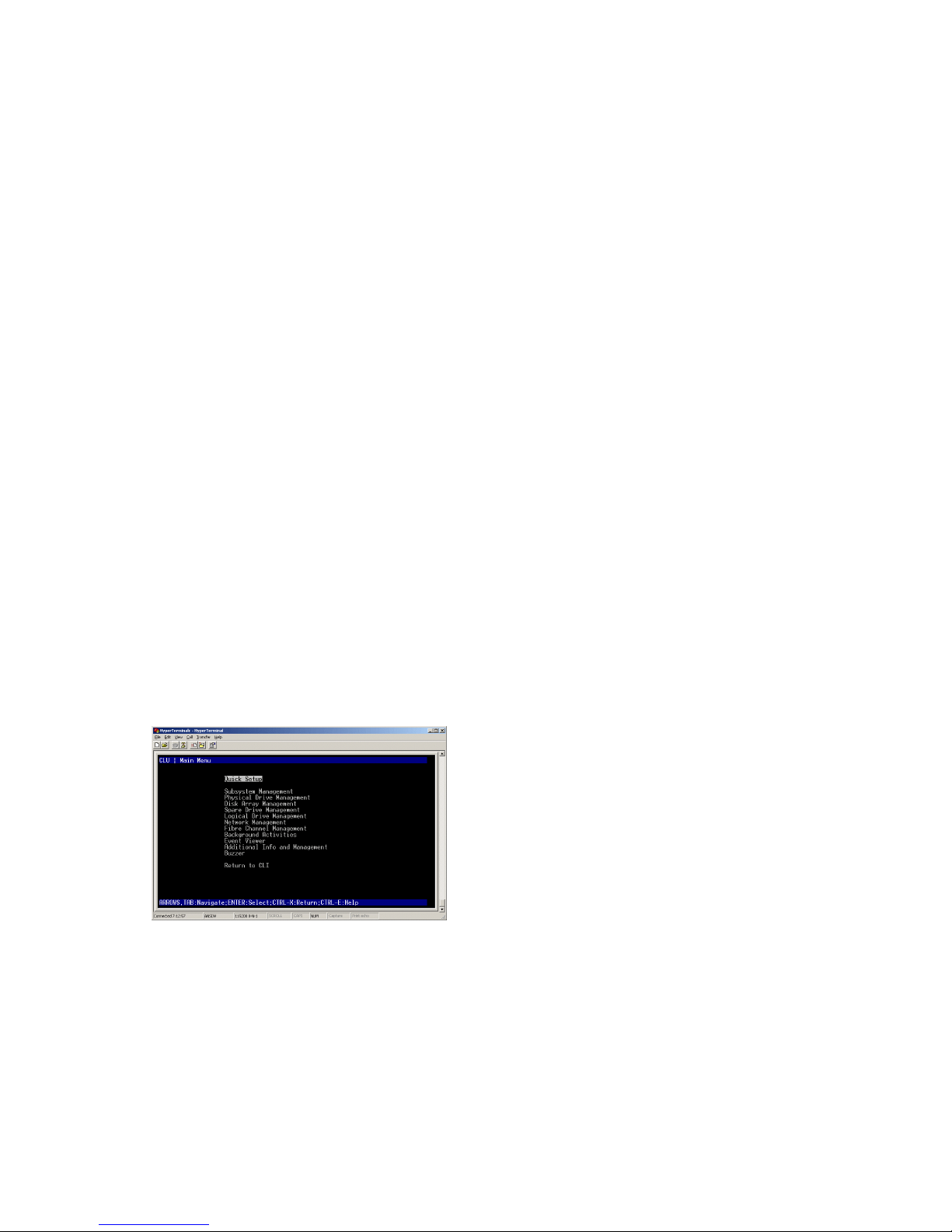
1. At the administrator@cli> prompt, type menu and press Enter.
The CLU main menu appears.
2. In the CLU Main Menu, highlight Network Management and press Enter, then highlight the management port and press Enter
S
ETTING UP WITH THE
CLU
1. At the administrator@cli> prompt, type menu and press Enter.
The CLU main menu appears.
Figure 26: CLU main menu
2. With Quick Setup highlighted, press Enter.
The first Quick Setup screen enables you to make Date and Time settings.
SETTING SYSTEM DATE AND TIME
To make date and time settings:
1. Press the arrow keys to highlight System Date.
2. Press the backspace key to erase the current date.
3. Type the new date.
4. Follow the same procedure to set the System Time.
5. Press Ctrl-A to save these settings and move to the Management Port configuration screen.
MAKING MANUAL IP SETTINGS
To make Management Port and iSCSI Port settings manually:

17
1. Press the arrow keys to highlight IP Address.
2. Press the backspace key to erase the current IP Address.
3. Type the new IP Address.
4. Follow the same procedure to specify the Subnet Mask, Gateway IP Address and DNS Server IP Address.
If you do not have a DNS server, skip the DNS Server IP Address.
5. Press Ctrl-A to save these settings and move to the RAID configuration screen.
MAKING AUTOMATIC IP SETTINGS
To make Management Port and iSCSI Port settings automatically:
1. Press the arrow keys to highlight DHCP.
2. Press the spacebar to toggle to Enable.
3. Press Ctrl-A to save these settings and move to the RAID configuration screen.
CONFIGURING THE RAID
You can configure your RAID arrays and logical drives using the CLU at this time. However, those actions are described in “Task 7:
Creating Logical Drives with Web- PAM PROe”. PROMISE suggests that you highlight Skip the Step and Finish and press Enter. Then
create your disk array using WebPAM PRO.
VIEWING IP ADDRESS AND SETTINGS
To view the current IP address and network settings when using DHCP:
1. In the CLU Main Menu, highlight Network Management and press Enter.
2. Highlight the Management Port or iSCSI Port you want and press Enter.
3. Highlight DHCP and press the spacebar to toggle to Disable.
The current Management or iSCSI Port settings are displayed.
4. Press the spacebar to toggle DHCP back to Enable.
5. Press Ctrl-A to save these settings and move to the RAID configuration screen.
EXITING THE CLU
In the CLU Main Menu, highlight Return to CLI and press Enter.
This completes the Management Port setup.
TASK 7: CREATING LOGICAL DRIVES WITH WEBPAM PROE
Setting up WebPAM PROe consists of the following actions:
• Logging into WebPAM PROe
• Choosing a Language
• Creating Your Logical Drives
• Logging out of WebPAM PROe
• Using WebPAM PROe over the Internet
LOGGING INTO WEBPAM PROE
1. Launch your Browser.
2. In the Browser address field, type the IP address of the Vess R2600 subsystem.
3. The initial HTTP connection is automatically redirected to a secure HTTPS connection.
Use the IP address you obtained in Task 7 (see “Task 6: Setting the IP Address”. Note that the IP address shown below is only an
example. The IP address you type into your browser will be different.
INITIAL CONNECTION
• WebPAM PROe uses an HTTP connection
• Enter the Vess R2600’s IP address
• Together, your entry looks like this:
SECURE CONNECTION
• WebPAM PROe uses a secure HTTP connection
• Enter the Vess R2600’s IP address
Together, your entry looks like this:
http://
10.0.0.1
http://10.0.0.1
https://
10.0.0.1
https://10.0.0.1
18
Note
Whether you choose a regular or a secure initial connection, your login to WebPAM PROe and your user password
are always secure.
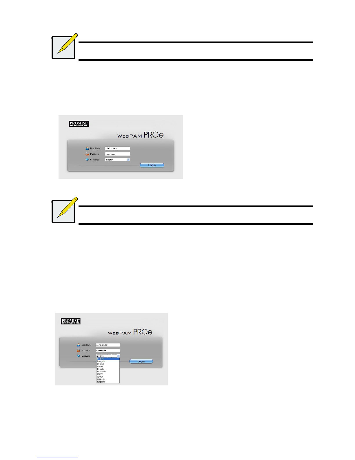
When the log-in screen appears:
• Type administrator in the User Name field.
• Type password in the Password field.
• Click the Login button.
The User Name and Password are case sensitive
Figure 27: WebPAM PROe log-in screen
After sign-in, the WebPAM PROe opening screen appears. If there are any unconfigured physical drives in the enclosure, an Array
Configuration menu also appears.
Note
Make a Bookmark (Firefox) or set a Favorite (Internet Explorer) of the Login Screen so you can access it easily next
time.
C
HOOSING A LANGUAGE
WebPAM PROe displays in English, German, French, Italian, Japanese, Korean, Traditional Chinese, and Simplified Chinese.
1. Choose the Language from the pull-down menu in the Login screen, or click Language on the WebPAM PROe Header after
logging in. - the language list appears in the Header.
2. Click the language you prefer.
The WebPAM PROe user interface displays in the chosen language.
Figure 28: Clicking “Language” on the WebPAM PROe Header
CREATING YOUR LOGICAL DRIVES
On a newly activated Vess R2600 subsystem, there are no disk arrays or logical drives. To create a logical drive:
1. Click the Disk Array icon, then click the Create tab.
The Array Configuration menu appears.
19
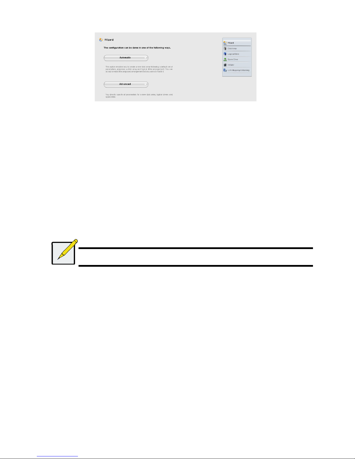
Figure 29: The Array Configuration menu
2. Choose one of the options:
• Automatic – Creates a new disk array following a default set of para-meters.
Makes one logical drive automatically. Also makes a hot spare drive for all RAID levels except RAID 0, if at least four
unconfigured physical drives are available.
• Advanced – You directly specify all parameters for a new disk array. Makes one logical drive automatically. You can create
additional logical drives at a later time, if additional configurable capacity is available. Does not make a hot spare drive.
3. Click the Next button.
Automatic
When you choose the Automatic option, the following parameters appear on the screen:
• Disk Arrays – The number of physical drives in the disk array, their ID numbers, configurable capacity, and the number of
logical drives to be created
• Logical Drives – The ID number of the logical drive(s), their RAID level, capacity, and stripe size
• Spare Drives – The physical drive slot number of the dedicated hot spare assigned to this disk array. A hot spare drive is
created for all RAID levels except RAID 0, when five or more unconfigured physical drives are available
If you accept these parameters, click the Submit button.
The new disk array appears in the Disk Array List on the Information tab.
If you do NOT accept these parameters, use the Express (below) or Advanced option to create your logical drive.
Advanced
Note
For an explanation of the parameters under the Advanced option, see the Vess R2600 Product Manual on the CD.
When you choose the Advanced option, the Step 1 – Disk Array Creation screen displays.
Step 1 – Disk Array Creation
1. Optional. Enter a name for the disk array in the field provided.
Maximum of 31 characters; letters, numbers, space between characters, and underline.
Uncheck the boxes if you want to disable Media Patrol or PDM. PROMISE recommends leaving these features enabled.
Highlight physical drives you want in the disk array from the Available list and press the >> button to move them to the Selected
list.
You can also double-click them to move them.
2. When you are done, click the Next button.
Step 2 – Logical Drive Creation
Optional. Enter an alias for the logical drive in the field provided.
Maximum of 31 characters; letters, numbers, space between characters, and underline.
Choose a RAID level for the logical drive from the dropdown menu.
The choice of RAID levels depends the number of physical drives you selected.
RAID 50 and 60 only – Specify the number of axles for your array.
Specify a Capacity and the unit of measure (B, KB, MB, GB, TB).
This value will be the data capacity of the first logical drive in your new disk array. If you specify less than disk array’s maximum
capacity, the remaining capacity is available for additional logical drives that you can create now or later.
20
3. For the following items, accept the default or choose a new value from the dropdown menu:
• Stripe size. 128 KB is the default.
• 64 KB, 128 KB, 256 KB, 512 KB, and 1 MB are available.
• Sector size. 512 B is the default.
• 512 B, 1 KB, 2 KB, and 4 KB are available.
• Read (cache) Policy. Read Ahead is the default.
• Read Cache, Read Ahead Cache, and No Cache are available.
• Write (cache) Policy. Write Back is the default.
Write Back and Write Through (Thru) are available.
4. Click the Update button.
A new logical drive is displayed under New Logical Drives. If there is free capacity remaining, you can specify another logical
drive now or wait until later.
5. When you are done specifying logical drives, click the Next button.
Step 3 – Summary
The Summary lists the disk array and logical drive information you specified.
To proceed with disk array and logical drive creation, click the Submit button.
Note
This function does not automatically create a hot spare drive. After the disk array is created, you can create a hot
spare drive for it. See the Vess R2600 Product Manual on the CD.
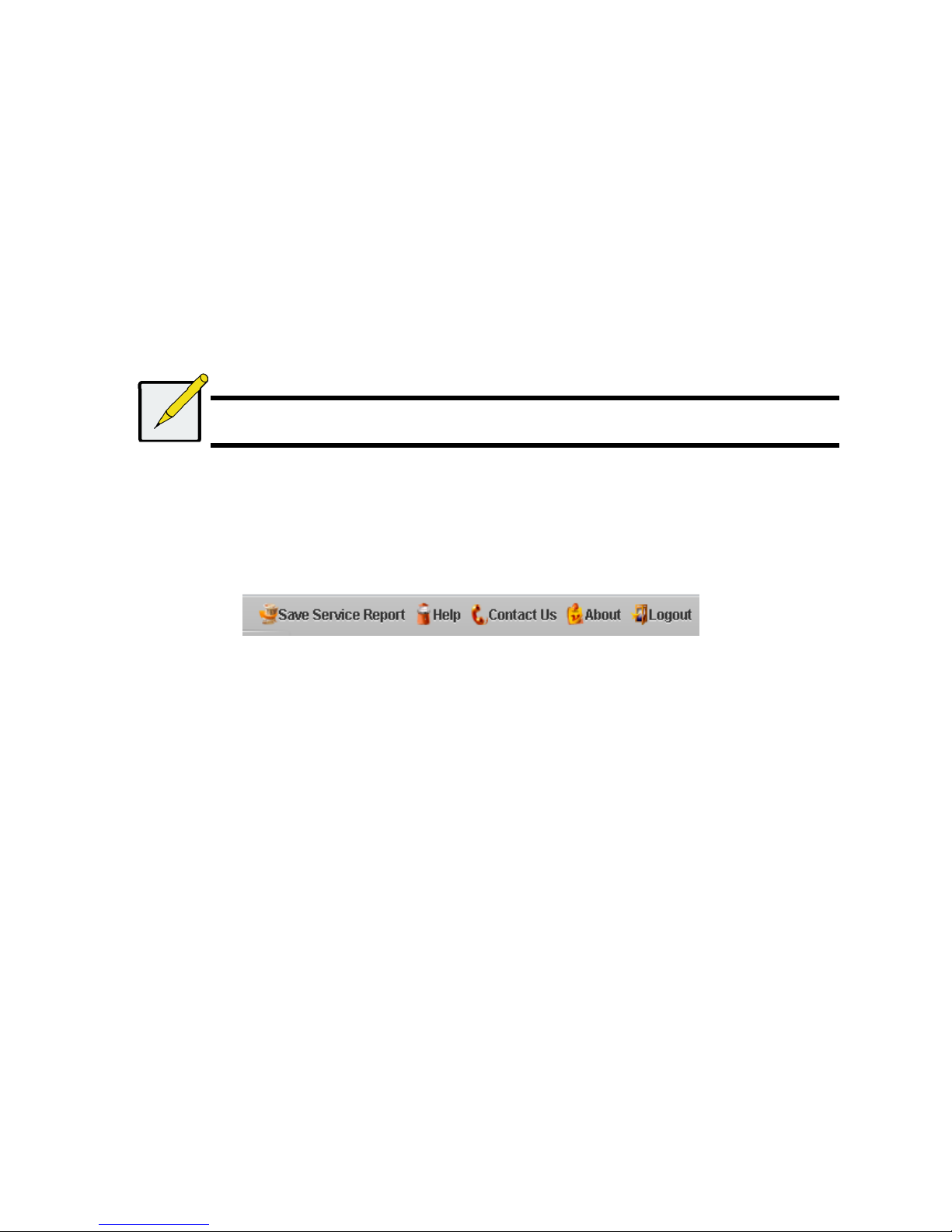
Logging out of WebPAM PROe
There are two ways to log out of WebPAM PROe:
• Close your browser window
• Click Logout on the WebPAM PROe banner
Figure 30: .Clicking “Logout” on the WebPAM PROe banner
Clicking Logout brings you back to the Login Screen.
After logging out, you must enter your user name and password in order to log in again.
USING WEBPAM PROE OVER THE INTERNET
The above instructions cover connections between Vess R2600 and your company nework. It is also possible to connect to a
Vess R2600 from the Internet.
Your MIS Administrator can tell you how to access your network from outside the firewall. Once you are logged onto the network, you
can access the Vess R2600 using its IP address.
CONTACTING TECHNICAL SUPPORT
PROMISE Technical Support provides several support options for PROMISE users to access information and updates. We encourage
you to use one of our electronic services, which provide product information updates for the most efficient service and support.
If you decide to contact us, please have the following information available:
• Product model and serial number
• BIOS, firmware and driver version numbers
• A description of the problem or situation
• System configuration information, including: motherboard and CPU type, hard drive models, SAS/SATA/ATA/ATAPI drives &
devices, and other controllers.

21
TECHNICAL SUPPORT SERVICES
PROMISE Online™ Website
http://www.promise.com/support/support_eng.asp
(technical documents, drivers, utilities, etc.)
E-mail Support e-Support On-Line
Phone
Support:
United States +1 408 228 1400 option 4
Australia/New Zealand +61 431586877
The Netherlands +31 0 40 235 2600
Germany +49 (0) 2 31 56 76 48 - 0
Italy +39 0 6 367 126 26
Japan +81-3-6801-8064
Taiwan +886 3 578 0002
Beijing, China +86 10 8857 8085 or 8095
Shanghai, China +86 21 6249 4192, 4193, or 4199
Russia
+7 (495) 666-20-63
22
Warnung
Dies ist ein Produkt der Klasse A. In einer Wohnumgebung
können Störungen beim Radio- oder Fernsehempfang verursacht
werden. In diesem Fall ist der Benutzer angehalten,
entsprechende Maßnahmen zu ergreifen.
Warnung
Die elektronischen Komponenten im Vess R2600 oder Vess
J2600 Gehäuse können durch elektrostatische Entladungen
(ESD) beschädigt werden. Beachten Sie stets die
entsprechenden Vorsichtsmaßnahmen, wenn Sie das Vess
R2600 Gerät oder seine Bauteile handhaben.
Achtung
* Es besteht das Risiko einer Explosion, wenn die Batterie
durch einen falschen Typ ersetzt wird.
* Entsorgen Sie verbrauchte Batterien gemäß den
Anweisungen, die der Batterie beiliegen.

23
INHALTSVERZEICHNIS
VESS R2600-ARBEITSSCHRITTE.....................................................25
SCHRITT 1: AUSPACKEN .................................................................25
VESS R2600 LIEFERUMFANG ..................................................25
VESS J2600 LIEFERUMFANG...................................................25
VESS R2000 SERIE MODELLVARIANTEN .................................25
VESS J2000 SERIE MODELLVARIANTEN ..................................25
SCHRITT 2: MONTAGE DES VESS R2600 IN EINEM RACK ..........27
SCHRITT 3: INSTALLIEREN VON FESTPLATTENLAUFWERKEN 30
LAUFWERKSTECKPLATZNUMMERIERUNG .............................30
INSTALLATION DER FESTPLATTENLAUFWERKE...................30
ANZAHL AN BENÖTIGTEN LAUFWERKEN................................31
SCHRITT 4: VERWALTUNGSANSCHLÜSSE...................................31
VERWALTUNGSPFAD NETZWERK (ETHERNET)
VERBINDUNG .............................................................................31
VERWALTUNGSPFAD SERIELLE VERBINDUNG ...................32
SAS JBOD ERWEITERUNG .........................................................33
KONFIGURATION DES DATENPFADES ..................................33
KONFIGURATION EINES VERWALTUNGSPFADES ...............33
SAS JBOD ERWEITERUNG.......................................................33
SCHRITT 5: ANSCHLIESSEN AN DIE STROMVERSORGUNG .34
LEDS AN DER VORDERSEITE ..................................................35
RÜCKSEITE PSU & LÜFTER LEDS...........................................36
CONTROLLER LEDS ....................................................................36
FESTPLATTENLAUFWERK LEDS ............................................36
SCHRITT 6: EINSTELLEN DER IP-ADRESSE.............................37
AUSWAHL VON DHCP ODER EINER STATISCHEN
IP-ADRESSE ...............................................................................37
Einrichtung mit dem CLU ..........................................................37
SYSTEMDATUM UND UHRZEIT EINSTELLEN.........................37

24
IP-EINSTELLUNGEN MANUELL VORNEHMEN .......................37
IP-EINSTELLUNGEN AUTOMATISCH VORNEHMEN ..............38
KONFIGURATION DES RAID.....................................................38
ANZEIGE VON IP-ADRESSE UND EINSTELLUNGEN.............38
BEENDEN DES CLU...................................................................38
SCHRITT 7: ERSTELLEN VON LOGISCHEN LAUFWERKEN
MIT WEBPAM PROE .....................................................................38
ANMELDEN BEI WEBPAM PROE .............................................38
ERSTMALIGE VERBINDUNG ....................................................38
SICHERE VERBINDUNG ............................................................38
AUSWAHL EINER SPRACHE............................................................39
ERSTELLEN IHRER LOGISCHEN LAUFWERKE........................39
VERWENDUNG VON WEBPAM PROE ÜBER DAS
INTERNET ...................................................................................41
Technischer Support....................................................................41
TECHNISCHE SUPPORT DIENSTE .............................................42
25
VESS R2600-ARBEITSSCHRITTE
• Schritt 1: Auspacken des Vess R2600/Vess J2600
• Schritt 2: Montage des Vess R2600/Vess J2600 in einem Rack
• Schritt 3: Installieren von Festplattenlaufwerken
• Schritt 4: Verwaltungsanschlüsse
• Schritt 5: Einrichtung von seriellen Kabelverbindungen
• Schritt 6: Anschließen an die Stromversorgung
• Schritt 7: Einstellen der IP-Adresse
• Schritt 8: Erstellen von logischen Laufwerken mit WebPAM PROe
• Technischer Support
SCHRITT 1: AUSPACKEN
Anmerkung
Die Vess R2000 Serie und Vess J2600 bieten Platz für SAS und SATA (3 Gbps/6 Gbps) Festplatten. SATA
Laufwerke benötigen einen zusätzlichen Adapter, der vor der Auslieferung installiert wird. Stellen Sie sicher, dass Sie
über die korrekten Laufwerksträger für die zu installierenden Festplatten verfügen. Sprechen Sie mit Ihrem Händler,
um weitere Informationen zu erhalten. Sehen Sie ebenfalls auf die Abbildungen der verschiedenen Laufwerksträger
unter „Schritt 3: Installieren von Festplattenlaufwerken“.
VESS R2600 LIEFERUMFANG
Die Vess R2600-Verpackung enthält die folgenden Komponenten:
• Vess R2600-Einheit (PTVR2K)
• Kurzanleitung (gedruckt)
• RJ11-auf-DB9 serielles Datenkabel
• Schrauben für Festplattenlaufwerk (70 Stück für 16
Schächte)
• 1,5 m (4,9 ft) Stromkabel (3 Kabel für 3 installierte
PSU, 4 Kabel für 4 installierte PSU)
• CD mit SNMP Dateien, Produkthandbuch und
Schnellstartanleitung im PDF Format
• Schiene für Rack-Montage
VESS J2600 LIEFERUMFANG
Die Vess J2600-Verpackung enthält die folgenden Komponenten:
• Vess J2600-Einheit (PTVJ2K)
• Kurzanleitung (gedruckt)
• RJ11-auf-DB9 serielles Datenkabel
• Schrauben für Festplattenlaufwerk (70 Stück für 16
Schächte)
• Schiene für Rack-Montage
• 1,5 m (4,9 ft) Stromkabel (3 Kabel für 3 installierte
PSU, 4 Kabel für 4 installierte PSU)
• SAS Kabel (1 Kabel J2600sS/2 Kabel J2600sD)
• CD mit SNMP Dateien, Produkthandbuch und
Schnellstartanleitung im PDF Format
VESS R2000 SERIE MODELLVARIANTEN
Modell
Controller
Einheiten
Interface
Anzahl
Laufwerke
Stromvers-
orgung
Kühler
R2600fiD 2 FC/iSCSI 16 3 2
R2600iD 2 iSCSI 16 3 2
R2600fiS 1 FC/iSCSI 16 3 2
R2600iS 1 iSCSI 16 3 2
VESS J2000 SERIE MODELLVARIANTEN
Modell
Controller
Einheiten
Interface
Anzahl
Laufwerke
Stromvers-
orgung
Kühler
J2600sD 2 SAS 16 3 2
J2600sS 1 SAS 16 3 2
26
Abbildung 1: Vess R2600-Vorderansicht
Ein defektes Laufwerk kann ohne Unterbrechung der Datenverfügbarkeit des Host Computers ausgetauscht werden. Falls konfiguriert,
wird ein Reservelaufwerk automatisch das defekte Laufwerk ersetzen und somit die Fehlertoleranzintegrität des logischen Laufwerks
sichern. Das selbsterhaltende Hardwarebasierte logische RAID Laufwerk bietet maximale Leistung in einem kompakten externen
Gehäuse.
Abbildung 2: Vess J2600-Vorderansicht
Anmerkung
Die Alarm Stumm Taste, die LEDs und USB Ports an der Vorderseite des linken Griffs des Vess J2600 sind ohne
Funktion.
Abbildung 3: Vess R2600fiD-Rückansicht
Festplattenträger Betriebs- und Status-LED
Festplattenträger
Betriebs- und Status-LED
Controller Module
Einheit 1 Einheit 2
PSU 1 PSU 2
Kühler
PSU 3
Einheit 1
mit Batterie
Einheit 2
mit Batterie
Stromversorgungen
(die Vess J2600 und Vess R2000 Serie wird
mit 3 installierten Stromversorgungen
ausgeliefert.)
Leerer Schacht für
optionale vierte
Stromversorgung
27
Abbildung 4: Vess R2600iD-Rückansicht
Abbildung 5: Vess J2600sD mit optionaler vierter Stromversorgung - Rückansicht
SCHRITT 2: MONTAGE DES VESS R2600 IN
EINEM RACK
Die Anweisungen beziehen sich auf die Vess R2600 und Vess J2600 Serie.
Achtung
* Statten Sie kein Gerät mit Festplatten aus, bis es nicht sicher im Rack installiert wurde.
* Mindestens zwei Personen werden benötigt, um den Vess R2600 oder Vess J2600 sicher in ein Rack System zu heben, zu
positionieren und zu befestigen.
* Heben oder bewegen Sie das Vess R2600 oder Vess J2600 Gerät nicht an den Griffen, Stromversorgungen oder den Controller
Einheiten. Halten Sie das Subsystem an sich fest.
* Installieren Sie das Vess R2600 oder Vess J2600 Gerät nicht ohne Schienen zur Unterstützung des Subsystems in einem Rack.
* Nur ein Fachtechniker, der mit dem Installationsvorgang vertraut ist, sollte das Vess R2600 oder Vess J2600 Gerät befestigen und
installieren.
* Befestigen Sie die Schienen mit den entsprechenden Schrauben und Flanschmuttern am Rack, und ziehen Sie sie an jedem Ende
der Schiene fest an.
* Belasten Sie die Schienen nicht, bis sie nicht wie beschrieben mit den Schrauben befestigt wurden.
* Die für die PROMISE Vess R2600 oder Vess J2600 Geräte verfügbaren Schienen bieten einen sicheren Halt für die PROMISE Vess
R2600 oder Vess J2600 Geräte, wenn sie richtig installiert wurden. Eine weitere Belastung der Schienen erfolgt auf eigenes Risiko.
* PROMISE Technology, Inc. kann nicht garantieren, dass die Montageschienen Ihr PROMISE Vess R2600 oder Vess J2600 Gerät
unterstützen werden, wenn sie nicht wie beschrieben installiert wurden.
Optionale
PSU 4
Controller Module
Einheit 1 Einheit 2
PSU 1 PSU 2
Kühler
PSU 3
Einheit 1
mit Batterie
Einheit 2
mit Batterie
Stromversorgungen
(die Vess J2600 und Vess R2000 Serie wird
mit 3 installierten Stromversorgungen
ausgeliefert.
)
Optionale
PSU 4
Controller Module
Einheit 1 Einheit 2
PSU 1 PSU 2
Kühler
PSU 3
Einheit 1
Einheit 2
Stromversorgungen
(die Vess J2600 und Vess R2000 Serie
wird mit 3 installierten Stromversorgungen
ausgeliefert.)
28
Das Vess R2600 oder Vess J2600 Gerät wird über die beiliegenden Montageschienen am Rack installiert.
Anmerkung
Sie können die Stromversorgungen entfernen, um das Vess R2600 oder Vess J2600 Gehäuse leichter zu machen.
Bringen Sie die Stromversorgungen wieder an, nachdem die Vess R2600 oder Vess J2600 Geräte in Ihrem Rack
befestigt wurden.
So installieren Sie das Vess R2600 Subsystem oder die Vess J2600 Erweiterung mit den beiliegenden Montageschienen in einem Rack:
1. Prüfen Sie den Sitz der Montageschienen in Ihrem Rack-System.
2. Passen Sie ggf. die Länge der Montageschienen an.
• Die hintere Schiene schiebt sich in die vordere Schiene. Die Schienenhälften werden ineinander vernietet und benötigen
keine Einstellungsschrauben.
• Die Enden der vorderen linken und vorderen rechten Montageschienen sind beschriftet.
• Stellen Sie sicher, dass die Stütze der vorderen Schiene an der Unterseite nach innen zeigt.
Abbildung 6: Installation der Schienen in das Rack
• Alle Schienenenden, vorne und hinten, werden an den Außenseiten der Rack-Stützen angebracht.
• Die Führungsstifte an den Schienenenden werden an den Öffnungen der Rack-Stützen ausgerichtet.
• Verwenden Sie die Befestigungsschrauben und Flanschmuttern Ihres Rack-Systems. Ziehen Sie die Schrauben und Muttern
gemäß der Anleitung Ihres Rack-Systems an.
Abbildung 7: Schienenenden werden an der Außenseite jeder Stütze angebracht
3. Platzieren Sie die Vess R2600 oder Vess J2600 Geräte auf die Schienen.
• Mindestens zwei Personen werden benötigt, um das Subsystem sicher anzuheben.
• Heben Sie das Vess R2600 oder Vess J2600 Gerät am Gerät selbst an. Heben Sie das Subsystem nicht an den Halterungen
an.
Vordere linke
Beschriftung
Vordere rechte
Beschriftung
Befestigungsflansch am
vorderen Ende der Schiene
Führungsstifte an den Schienen mit den
Öffnungen an den Rack-Stützen ausrichten
Schienenenden werden
an der Außenseite der
vorderen und hinteren
Rack-Stützen befestigt
 Loading...