

Vess R2000 Series, J2000 Series, R2600tiD, R2600xiD, R2600fiD Quick Start Manual
...

Vess R2000 Series
Vess J2000 Series
Quick Start Guide
Version 2.2
Contents
English … Page 001 ~ 039
Deutsch
Français
Italiano
Español
Русский
日本語
繁體中文
简体中文
한국어
… Page 040 ~ 078
… Page 079 ~ 117
… Page 118 ~ 156
… Page 157 ~ 195
… Page 196 ~ 234
… Page 235 ~ 273
… Page 274 ~ 312
… Page 313 ~ 351
… Page 352 ~ 390
© 2014 PROMISE Technology, Inc. All Rights Reserved.
PTVR2K
PTVJ2K
Warning
This is a Class A product. In a domestic environment this product may
cause radio interference in which case the user may be required to
take adequate measures.
Warning
The electronic components within the Vess R2600 or Vess J2600
enclosure are sensitive to damage from Electro-Static Discharge
(ESD). Observe appropriate precautions at all times when handling
the Vess R2600 or its subassemblies.
Caution
There is a risk of explosion if the battery is replaced by the incorrect
type.
Caution
Dispose of used batteries according to the instructions that
accompany the battery.
Caution
Disconnect all power cords before servicing the Vess enclosure.
1

Contents
VESS R2600 TASK LIST 4
TASK 1: UNPACKING 4
VESS R2600 PACKING LIST 4
VESS J2600 PACKING LIST 5
VESS R2000 SERIES MODEL LINE-UP 5
VESS J2000 SERIES MODEL LINE-UP 5
TASK 2: MOUNTING Vess R2600 IN A RACK 10
TASK 3: INSTALLING DISK DRIVES 14
DRIVE SLOT NUMBERING 14
INSTALLING YOUR DISK DRIVES 15
NUMBER OF DRIVES REQUIRED 16
TASK 4: MANAGEMENT CONNECTIONS 17
MANAGEMENT PATH NETWORK (ETHERNET) CONNECTION 17
MANAGEMENT PATH SERIAL CONNECTION 19
Connecting a Fibre Channel SAN 20
FCData Path 20
Connecting the iSCSINetwork 21
1GbEand10GbEData Path 22
SAS JBOD EXPANSION 23
CONFIGURING THE DATA PATH 23
CONFIGURING A MANAGEMENT PATH 24
TASK 5: CONNECTING THE POWER 25
FRONT PANEL LEDS 27
REAR PANEL PSU & COOLING FAN LEDS 28
CONTROLLER LEDS 29
DISK DRIVE LEDS 29
TASK 6: SETTING THE IP ADDRESS 30
CHOOSING DHCP OR A STATIC IP ADDRESS 30
2

SETTING SYSTEM DATE AND TIME 31
MAKING MANUAL IP SETTINGS 32
MAKING AUTOMATIC IP SETTINGS 32
CONFIGURING THE RAID 32
VIEWING IP ADDRESS AND SETTINGS 32
EXITING THE CLU 32
TASK 7: CREATING LOGICAL DRIVES WITH WEBPAM PROE 33
LOGGING INTO WEBPAM PROE 33
INITIAL CONNECTION 33
SECURE CONNECTION 33
CHOOSING A LANGUAGE 34
CREATING YOUR LOGICAL DRIVES 35
USING WEBPAM PROE OVER THE INTERNET 38
CONTACTING TECHNICAL SUPPORT 39
TECHNICAL SUPPORT SERVICES 39
3

VESS R2600 TASK LIST
Note
The Vess R2000 series and Vess J2600 can accommodate SAS and SATA
(3Gbps/6Gbps) hard drives. SATA drives require an additional adapter that is
installed before shipping (option). Make sure you have the correct drive carriers
for the hard drives that will be installed. Talk to your vendor for more information.
See page 16 for pictures of the two carrier adapters.
Important
Release 2 of the Vess 2000 Series supports simultaneous NAS and SAN
operation. This Quick Start Guide does not include instructions for setting up
RAID storage used for NAS. Using the NAS feature might change how you
layout and connect cabling. Please refer to the Product Manual for important
information on planning and setting up the Vess R2000 Series for NAS
operation.
• Task 1: Unpacking
• Task 2: Mounting Vess R2600 in a Rack
• Task 3: Installing Disk Drives
• Task 4: Management and Data Connections
• Task 5: Connecting the Power
• Task 6: Setting the IP Address
• Task 7: Creating Logical Drives with WebPAM PROe
Also in this guide: Contacting Technical Support
TASK 1: UNPACKING
VESS R2600 PACKING LIST
The Vess R2600 box contains the following items:
• Vess R2600 Unit (PTVR2K)
• Quick Start Guide printed
• RJ11-to-DB9 serial data cable
• Screws for disk drives (70 pieces for
16-bay)
• 1.5m (4.9 ft) Power cords (3 cords for
3 PSU installed, 4 cords for 4 PSU
installed)
• CD with SNMP files, Product Manual
and Quick Start Guide in PDF format
• Sliding rail assembly for rack mounting
4

VESS J2600 PACKING LIST
Model
Controller Units
Interface
Number of
Drives
Power
Supplies
Cooling
Units
R2600fiD
2
FC/iSCSI
16 3 2
R2600iD
2
iSCSI
16 3 2
R2600tiD
2
iSCSI (4x1Gb,
2x10Gb per
controller)
16 3 2
R2600xiD
2
iSCSI (4x1Gb,
2x10Gb SFP+ per
controller)
16 3 2
R2600fiS
1
FC/iSCSI
16 3 2
R2600iS
1
iSCSI
16 3 2
R2600tiS
1
iSCSI
4x1Gb, 2x10Gb
16 3 2
R2600xiS
1
iSCSI
(4x1Gb, 2x10Gb
SFP+)
16 3 2
Model
Controller Units
Interface
Number of
Drives
Power
Supplies
Cooling
Units
J2600sD
2
SAS
16 3 2
J2600sS
1
SAS
16 3 2
The Vess J2600 box contains the following items:
• Vess J2600 Unit (PTVJ2K)
• Quick Start Guide printed
• RJ11-to-DB9 serial data cable
• Screws for disk drives (70 pieces for 16-
bay)
• Sliding rail assembly for rack mounting
VESS R2000 SERIES MODEL LINE-UP
• 1.5m (4.9 ft) Power cords (3 cords for
3 PSU installed, 4 cords for 4 PSU
installed)
• SAS cable (1 cable J2600sS/ 2 cables
J2600sD)
• CD with SNMP files, Product Manual
and Quick Start Guide in PDF format
VESS J2000 SERIES MODEL LINE-UP
5
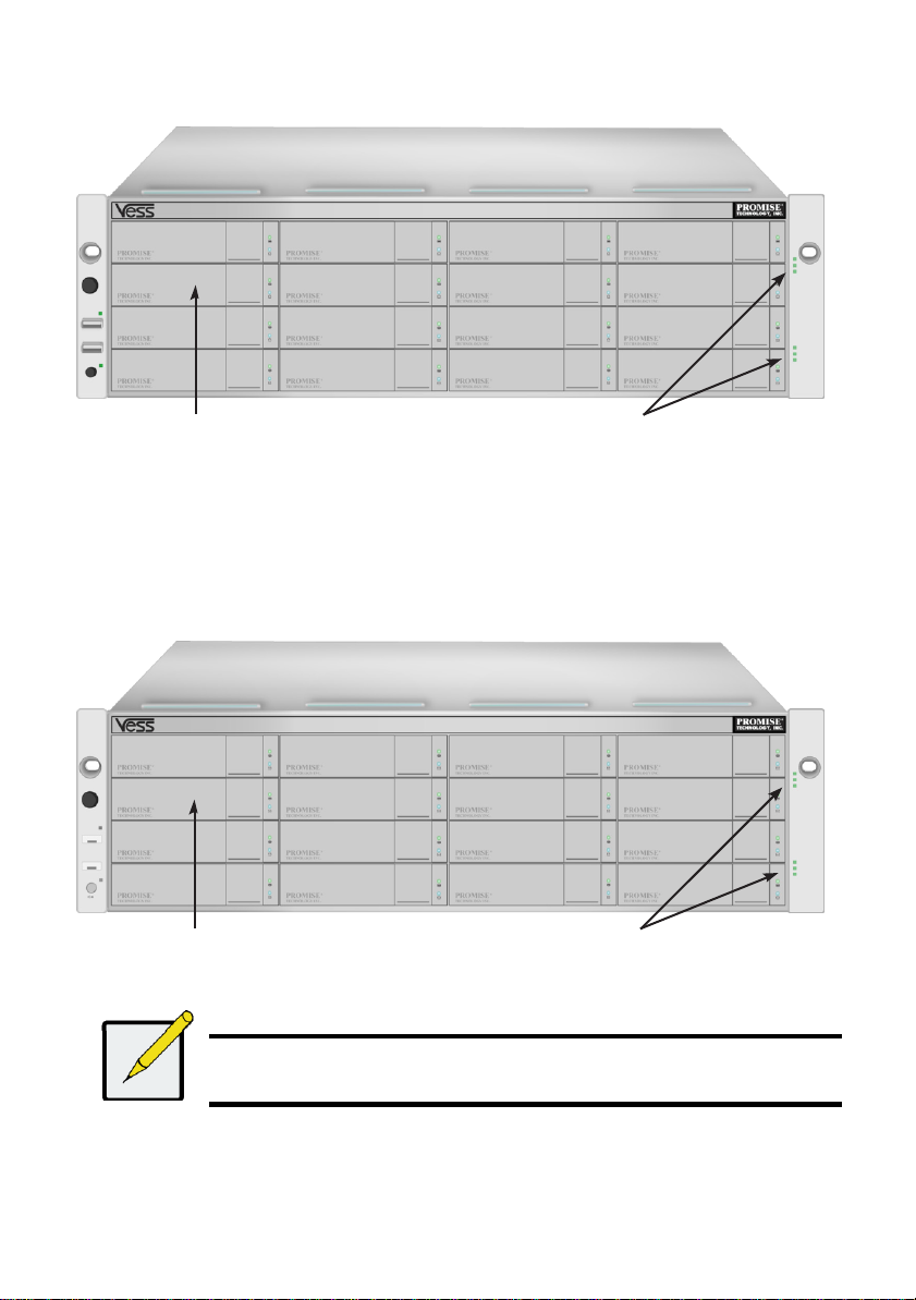
Figure 1: Vess R2600 front view
Note
The Alarm Mute button, the LEDs and USB ports on the front of the left handle
of the Vess J2600 are nonfunctional.
Drive carriers
Power and Status LEDs
Drive carriers
Power and Status LEDs
A defective drive may be replaced without interruption of data availability to the host computer. If so
configured, a hot spare drive will automatically replace a failed drive, securing the fault-tolerant
integrity of the logical drive. The self-contained hardware- based RAID logical drive provides
maximum performance in a compact external enclosure.
Figure 2: Vess J2600 front view
6
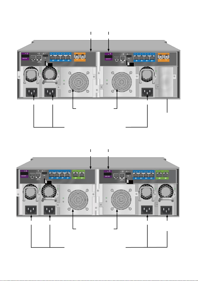
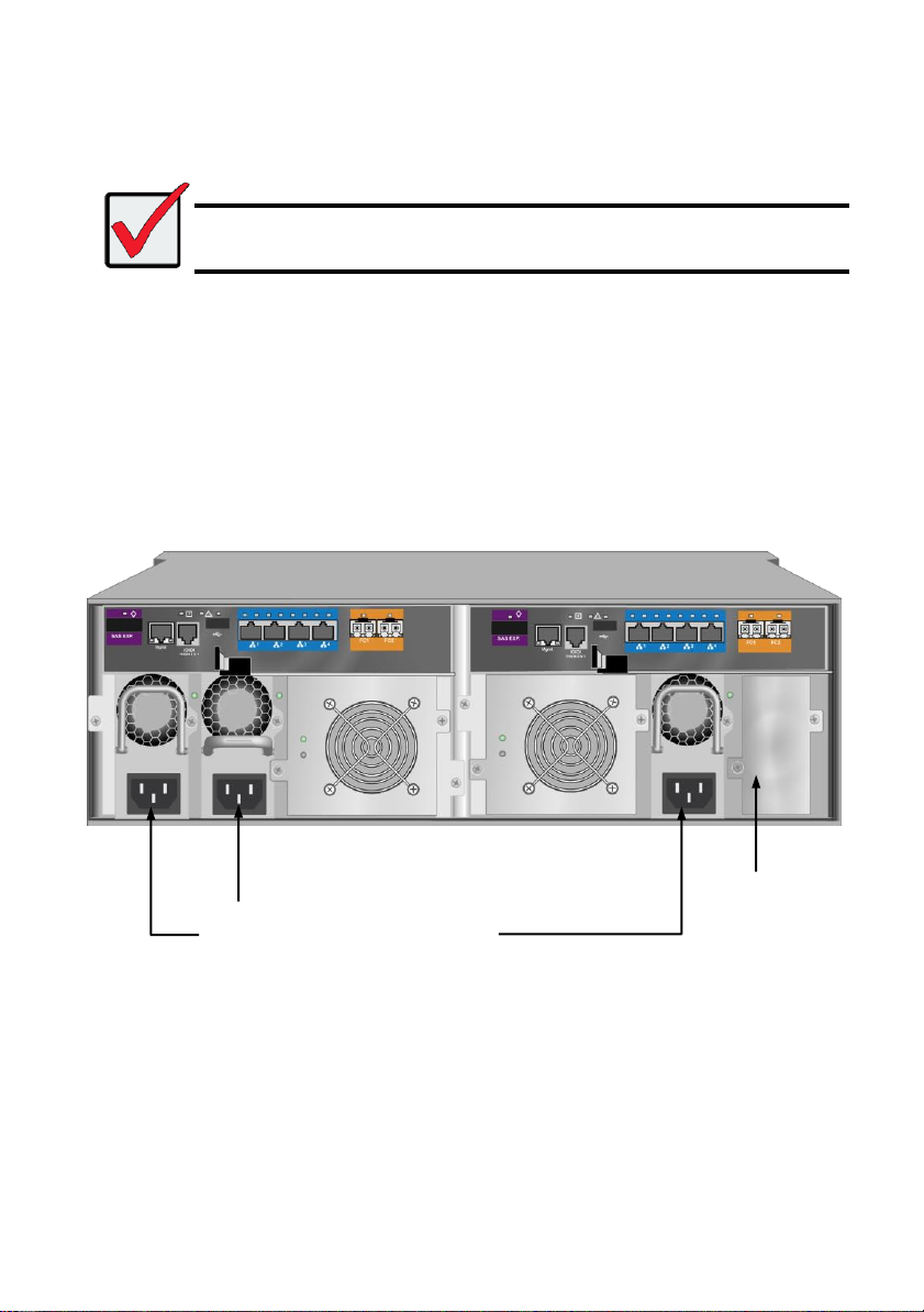
Figure 3: Vess R2600fiD rear view
Controller modules
Unit 1 Unit 2
Cooling units
Unit 1
with battery
Unit 2
with battery
Power supplies
(Vess J2600 and Vess R2000 Series are
shipped with 3 power supplies installed.)
Empty bay for
optional fourth
power supply
PSU 1
PSU 2
PSU 3
Controller modules
Unit 1 Unit 2
Cooling units
Unit 1
with battery
Unit 2
with battery
Power supplies
(Vess J2600 and Vess R2000 Series are
shipped with 3 power supplies installed.)
PSU 1
PSU 2
Optional
PSU 4
Figure 4: Vess R2600tiD rear view
7
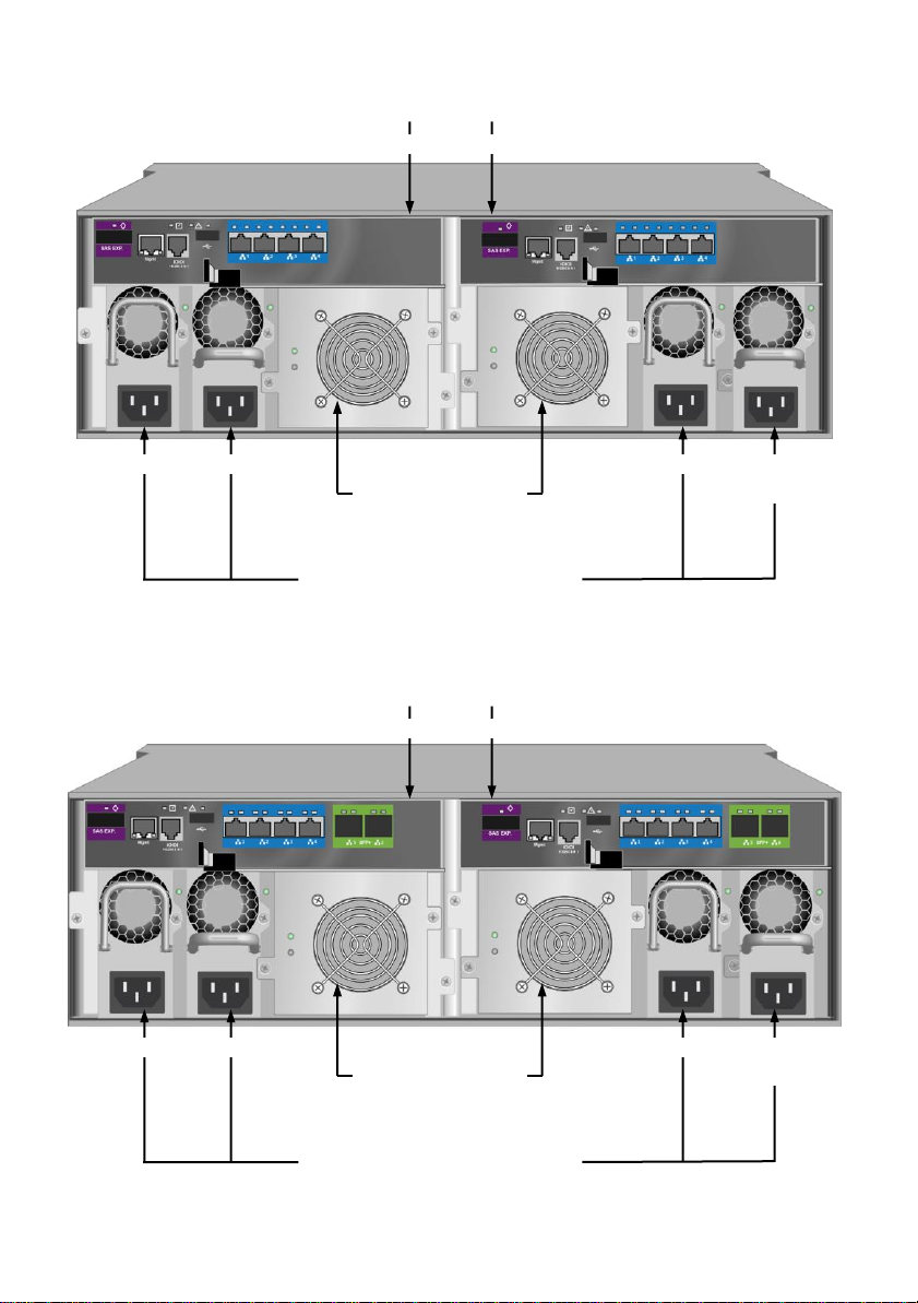
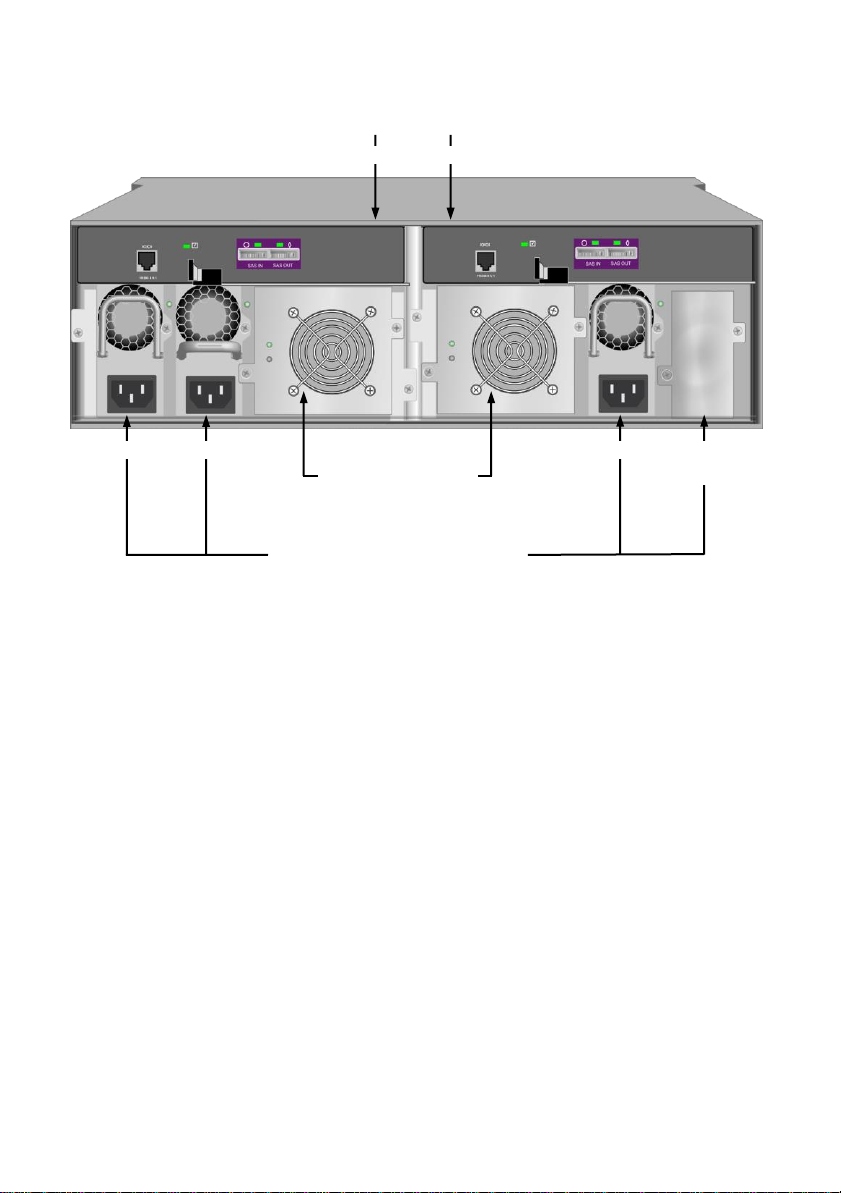
Figure 5: Vess R2600iD rear view
Controller modules
Unit 1 Unit 2
Cooling units
Unit 1
with battery
Unit 2
with battery
Power supplies
(Vess J2600 and Vess R2000 Series are
shipped with 3 power supplies installed.)
PSU 1
PSU 2
PSU 3
Optional
PSU 4
Controller modules
Unit 1 Unit 2
Cooling units
Unit 1
with battery
Unit 2
with battery
Power supplies
(Vess J2600 and Vess R2000 Series are
shipped with 3 power supplies installed.)
PSU 1
PSU 2
Optional
PSU 4
Figure 6: Vess R2600xiD rear view
8
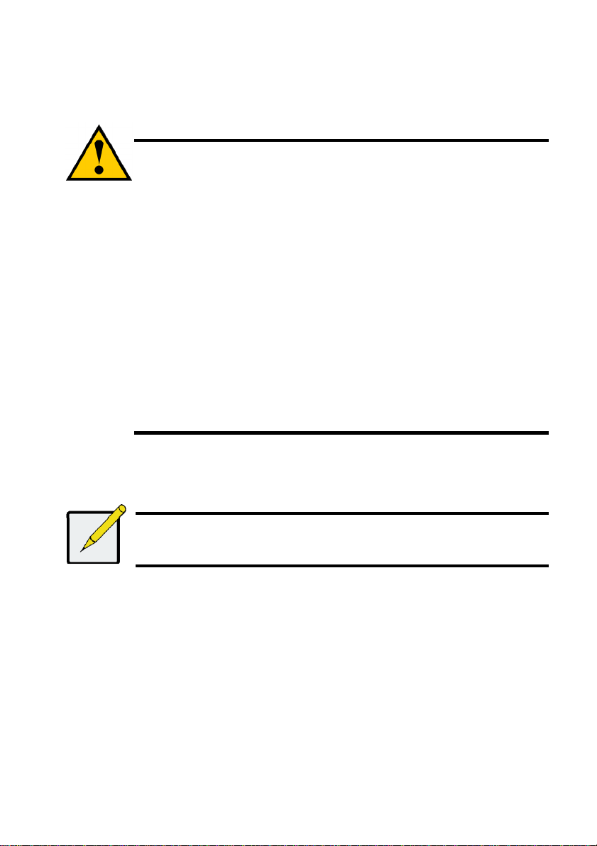
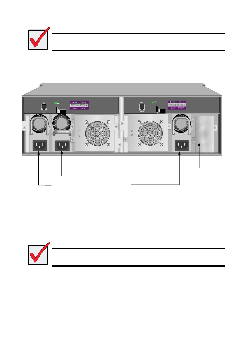
Controller modules
Unit 1 Unit 2
Cooling units
Unit 1
Unit 2
Power supplies
(Vess J2600 and Vess R2000 Series are
shipped with 3 power supplies installed.)
PSU 1
PSU 2
PSU 3
Optional
PSU 4
Figure 7: Vess J2600sD with optional four power supplies - rear view
9
Cautions
* Do not populate any unit with hard drives until it has been securely installed in
the rack.
* At least two persons are required to safely lift, place, and attach the Vess
R2600 or Vess J2600 unit into a rack system.
* Do not lift or move the Vess R2600 or Vess J2600 unit by the handles, power
supplies or the controller units. Hold the subsystem itself.
* Do not install the Vess R2600 or Vess J2600 unit into a rack without rails to
support the subsystem.
* Only a qualified technician who is familiar with the installation procedure
should mount and install the Vess R2600 or Vess J2600 unit.
* Mount the rails to the rack using the appropriate screws and flange nuts, fully
tightened, at each end of the rail.
* Do not load the rails unless they are installed with screws as instructed.
* The rails available for the PROMISE Vess R2600 or Vess J2600 unit are
designed to safely support that PROMISE Vess R2600 or Vess J2600 unit
when properly installed. Additional loading on the rails is at the customer’s risk.
* PROMISE Technology, Inc. cannot guarantee that the mounting rails will
support your PROMISE Vess R2600 or Vess J2600 unit unless you install
them as instructed.
Note
To lighten the Vess R2600 or Vess J2600 enclosure, you can remove the power
supplies. Replace the power supplies after the Vess R2600 or Vess J2600 unit is
mounted in your rack.
TASK 2: MOUNTING Vess R2600 IN A RACK
The instructions here apply to the Vess R2600 and Vess J2600 series.
The Vess R2600 or Vess J2600 installs to the rack using the mounting rails shipped with the device.
10
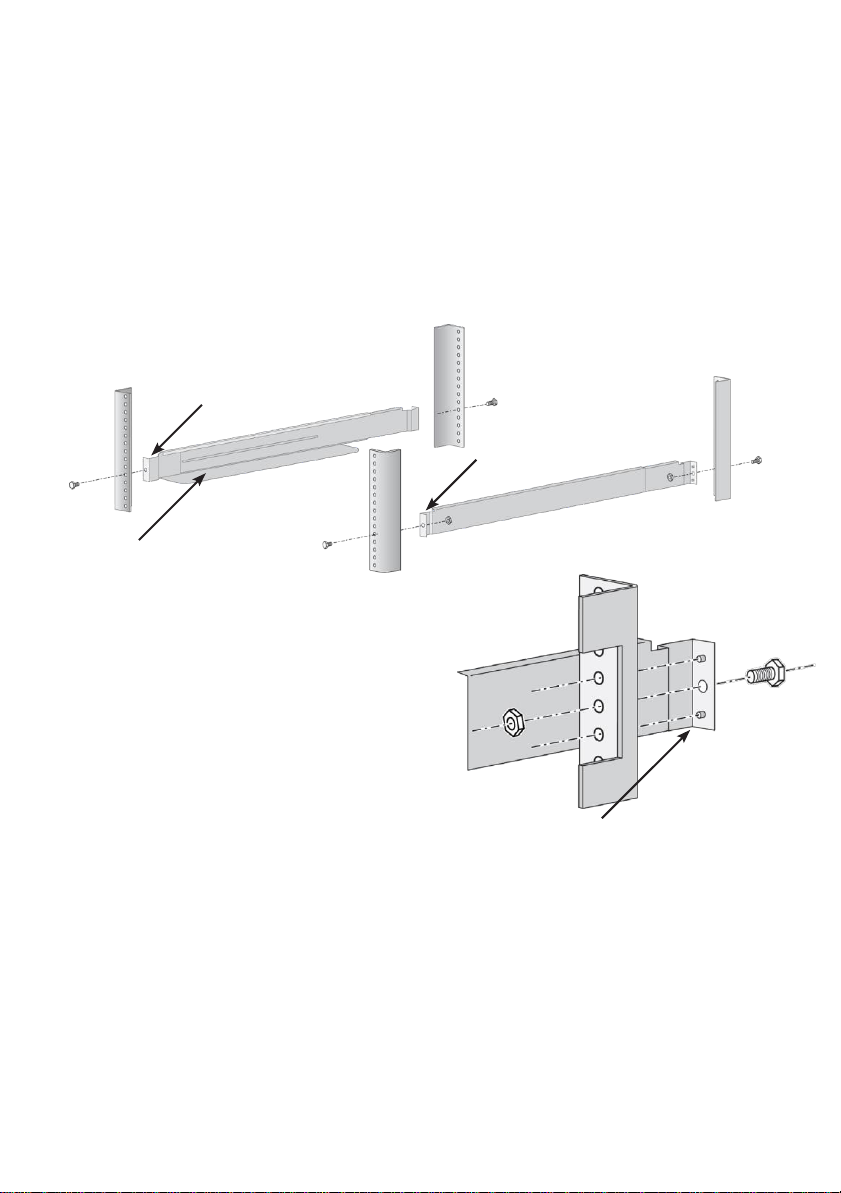
To install the Vess R2600 subsystem or Vess J2600 expansion into a rack with the supplied
Front left label
Support flange on the
front end of
each rail
Guide pins on rails align with holes in
the rack post
Front right label
mounting rails:
1. Check the fit of the mounting rails in your rack system.
2. Adjust the length of the mounting rails as needed.
• The rear rail slides inside the front rail. The rail halves are riveted together and use no
adjustment screws.
• The front-left and front-right mounting rail ends are labeled.
• Be sure the front rail support is on the bottom facing inward.
Figure 8: Installing the rails onto the rack
• All rail ends, front and rear, attach at the outside of the rack posts.
• The guide pins at the rail ends align with the holes in the rack posts.
• Use the attaching screws and flange nuts from your rack system. Tighten the screws and
nuts according to instructions for your rack system.
11
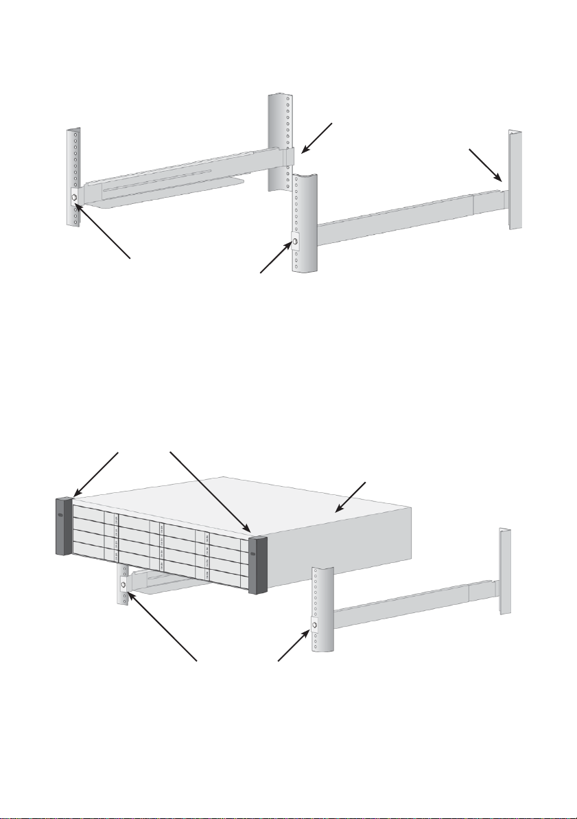
Rail ends attach on the
outside of the front and rear
rack posts
Brackets
Vess R2600 (or Vess
J2600) subsystem
Rails installed
and tightened
Figure 9: Rail ends attach to the outside of each post
3. Place the Vess R2600 or Vess J2600 onto the rails.
• At least two persons are required to safely lift the subsystem.
• Lift the Vess R2600 or Vess J2600 itself. Do not lift the subsystem by its brackets.
Figure 10: Placing the subsystem onto the rack rails
12
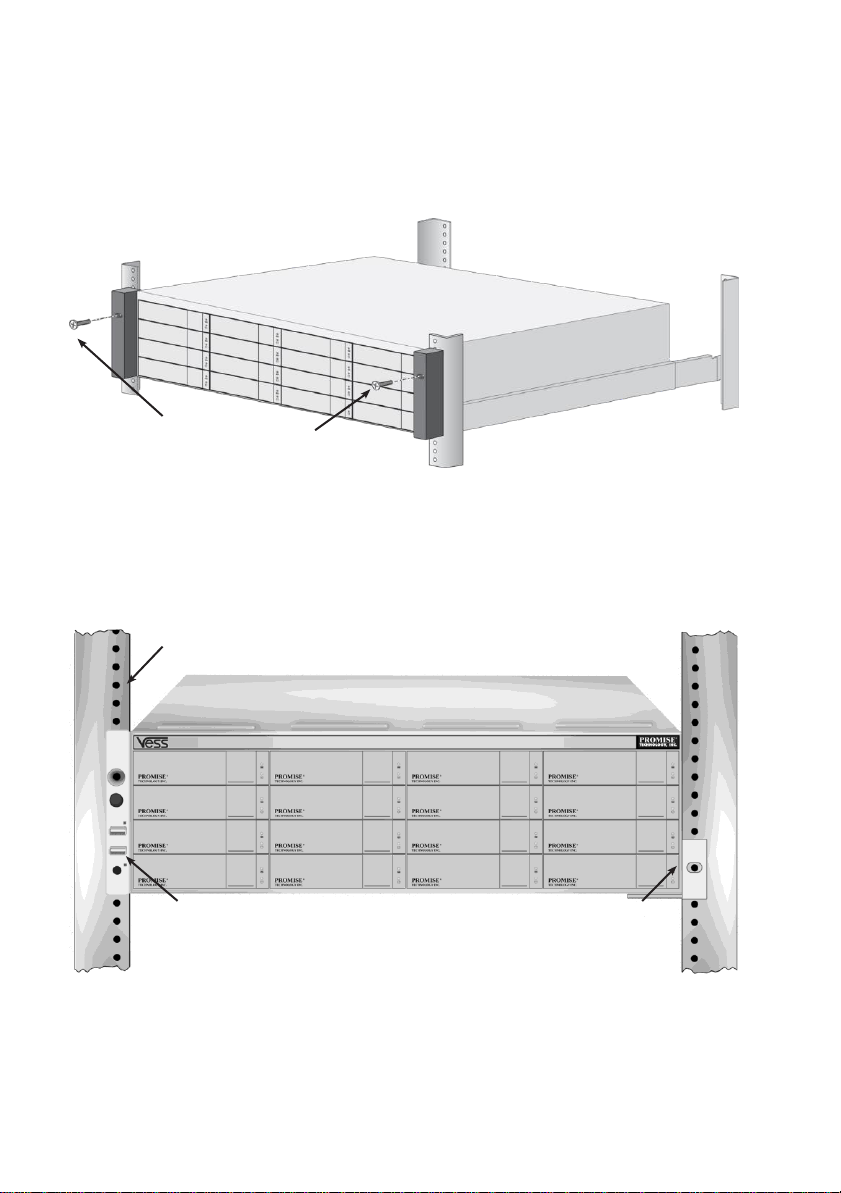
Screws and flange nuts
attach the Vess R2600
to the rack posts
Vertical rack post
Handles mount outside
the rack post
Mounting rails
mount outside the
rack post
4. Secure the Vess R2600 or Vess J2600 to the rack.
• The unit attaches to the rack posts using the included screws and flange nuts.
One screw each side, in the upper hole only.
• Use the attaching screws and flange nuts that came with the Vess R2600 or Vess J2600.
Figure 11: Secure to rack
Figure 12: Subsystem installed in rack
13
TASK 3: INSTALLING DISK DRIVES
The Vess R2600 subsystems and Vess J2600 expansion units support:
• SAS hard disk drives
• SATA hard disks (requires additional factory installed adapter see Figures 15 and 16 below)
• 3.5-inch hard disk drives
• 2.5-inch hard disk drives
For a list of supported physical drives, download the latest compatibility list from the PROMISE
support website.
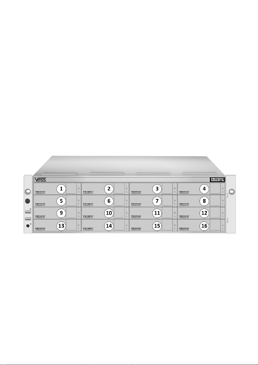
DRIVE SLOT NUMBERING
You can install any qualified disk drive into any slot in the enclosure. The diagram below shows how
drive slots are numbered on both the Vess R2600 and Vess J2600.
Slot numbering is reflected in the WebPAM PROe and CLU user interfaces.
Figure 13: 16-bay Drive slot numbering (Vess R2600 and Vess J2600)
Install all of the drive carriers into the enclosure to ensure proper airflow, even if you do not populate
all the carriers with disk drives.
14
Caution
The Vess R2600 and Vess J2600 support disk drive hot-swapping. To
avoid hand contact with an electrical hazard, do not remove more than
one drive carrier a time.
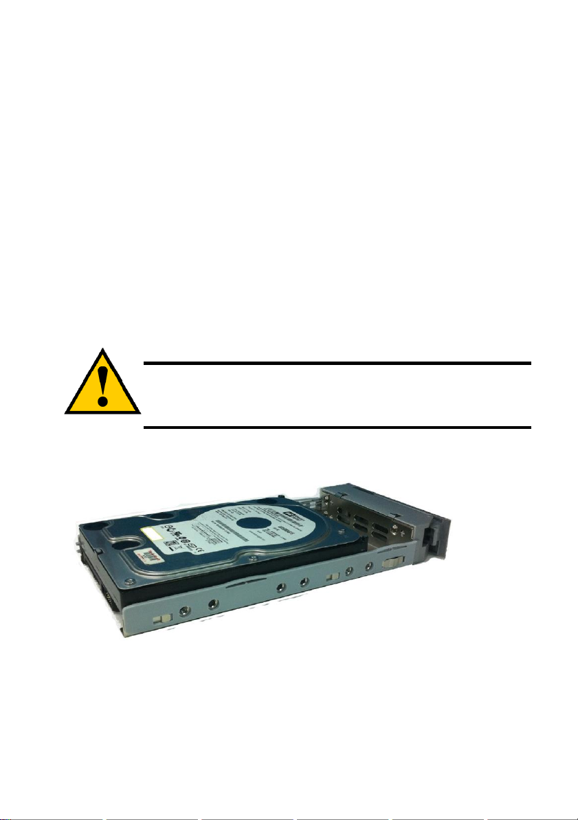
INSTALLING YOUR DISK DRIVES
The instructions below apply to all types of drive carriers intended for use with the Vess R2600 or
Vess J2600. Note that SATA drives require additional SAS-to-SATA adapters to work properly in a
dual RAID controller models. If you intend to use SATA hard drives, make sure the drive carriers
shipped with the unit are appropriate for your SATA drive. See Figures 14 and 15 for examples of
drive carriers for SATA hard drives.
1. Remove a disk drive carrier.
2. Carefully lay the disk drive into the drive carrier at the front, so that the screw holes on the
sides line up.
3. Insert the screws through the holes in the drive carrier and into the sides of the disk drive.
Install only the counter-sink screws supplied with the Vess J2600.
• Install four screws per drive.
• Snug each screw. Be careful not to over-tighten.
4. Reinstall the drive carrier into the Vess J2600 enclosure.
Repeat steps 1 through 3 until all of your disk drives are installed.
Figure 14: SAS disk drive mounted in a drive carrier
15
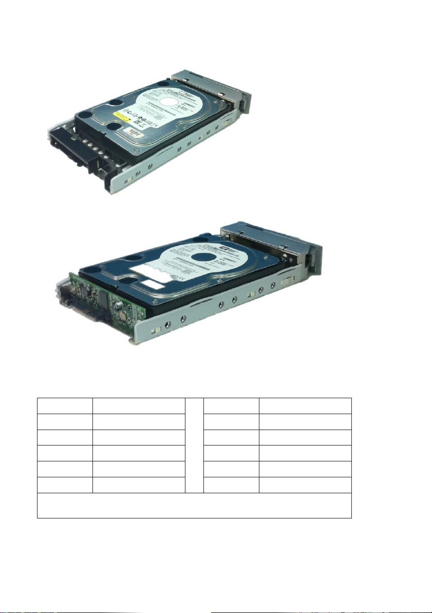
Use the Blackjack adapter for SATA 6Gbs drives and the AAMUX adapter for 3 Gbs SATA drives.
Figure 15: SATA disk drive mounted in carrier with Blackjack adapter
Figure 16: SATA disk drive mounted in carrier with AAMUX adapter
Level
Number of Drives
Level
Number of Drives
RAID 0
1 or more
RAID 6
4 to 32*
RAID 1
2 only
RAID 10
4 or more**
RAID 1E
2 or more
RAID 30
6 or more
RAID 3
3 to 32*
RAID 50
6 or more
RAID 5
3 to 32*
RAID 60
8 or more
* A JBOD expansion unit may be required.
** Must be an even number of drives.
NUMBER OF DRIVES REQUIRED
The table below shows the number of drives required for each RAID level
16
Important
For a list of supported FC HBAs, Switches and SFPs, download the latest
compatibility list from the PROMISE support website:
http://www.promise.com/support/
Vess R2600 does not support cascading of multiple RAID subsystems. Cascading
is planned for a future release.
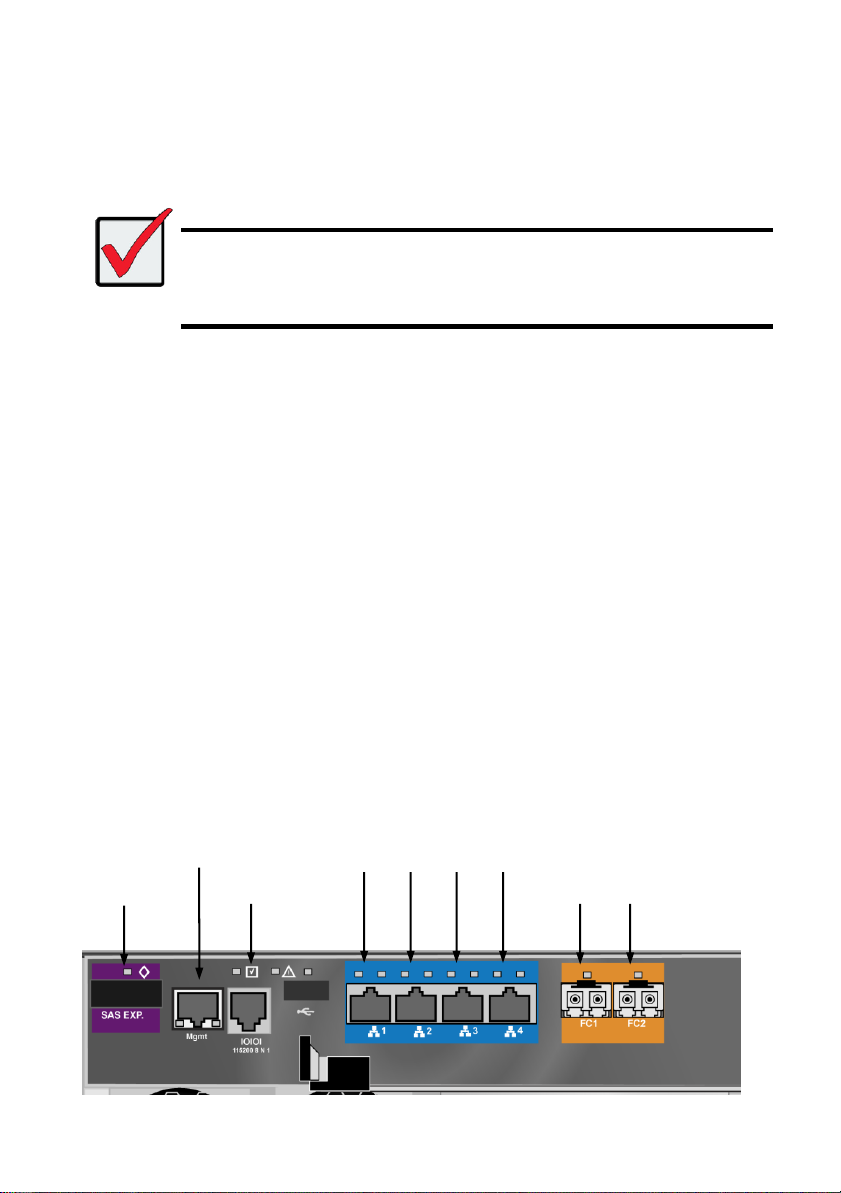
SAS
expansion port
Network
mgmt port
Console
mgmt port
1 G data ports
1 2 3 4
FC data ports
1 2
TASK 4: MANAGEMENT CONNECTIONS
This section describes how to establish a management connection the Vess R2600 subsystem.
There are two methods to establish a management connection to the Vess R2600. The Vess J2600
system is managed through a Vess R2600 subsystem that is attached via the SAS expansion link.
MANAGEMENT PATH NETWORK (ETHERNET) CONNECTION
The Vess R2600 controller has one (1) Ethernet RJ-45 Management Port connector.
See page 17 for illustrations of controller interfaces.
To establish the management path:
1. Attach one end of an Ethernet cable to the network connector or standard NIC in the Host
PC.
Attach the other end of the Ethernet cable to one of the ports on the standard network
switch.
2. Attach one end of an Ethernet cable to one of the ports on the standard network switch.
Attach the other end of the Ethernet cable to the Management Port on the Vess R2600
subsystem.
If you have multiple Vess R2600 subsystems, Host PCs or Servers, repeat steps 1 and 2 as
required.
Figure 17: Vess R2600fi controller data and management ports
17
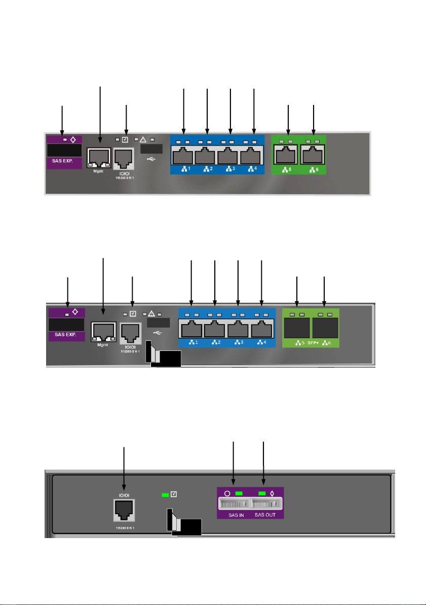
SAS
expansion port
Network
mgmt port
Console
mgmt port
1 G data ports
1 2 3 4
10 Gb data ports
5 6
Console mgmt port
(used for diagnostics, JBODs are
managed through a Vess R2600 unit
connected via SAS expansion)
SAS data ports
1 2
SAS
expansion port
Network
mgmt port
Console
mgmt port
1 G data ports
1 2 3 4
10 Gb SPF+ data
ports
5 6
Figure 18: Vess R2600ti controller management and data ports
Figure 19: Vess R2600xi controller management and data ports
Figure 20: Vess J2600s controller management and data ports
18
Serial port (RJ-11)
MANAGEMENT PATH SERIAL CONNECTION
Vess R2600 has a Command Line Interface (CLI) to manage all of its functions. A subset of the CLI
is the Command Line Utility (CLU), a user-level interface that manages your Vess R2600 via your
PC’s terminal emulation program, such as Microsoft HyperTerminal.
Serial communication enables the terminal emulation application on your host PC or server to
access the Vess R2600 Command Line Interface (CLI) to set up a network connection. The Vess
R2600 package includes one RJ11-to-DB9 serial data cable for each controller.
Figure 21: Serial connector
To set up a serial cable connection:
1. Attach the RJ11 end of the serial data cable to the RJ11 serial connector on one of the
RAID controllers.
2. Attach the DB9 end of the serial data cable to a serial port on the host PC or server.
19
Connecting a Fibre Channel SAN
A Fibre Channel SAN using the Vess R2600fi controller requires the following items:
• An FC HBA card in each host PC or server
• An SFP transceiver for each connected FC port on the subsystem
• An FC switch
• A network switch
• FC cabling (LC/LC 62.5/125μm MMF)
For other FC connections such as Direct Attached Storage (DAS) please refer to the Product
Manual.
Figure 22: Management and FC data connections on R2600fi
FC Data Path
To establish the data path:
1. Connect FC cables between at least one FC data port on each RAID controller and the FC
switch.
2. Connect FC cables between the FC switch and the FC HBA cards in both host PCs or
servers.
If you have multiple Vess R2600 subsystems, repeat steps 1 and 2 as required.
20
Connecting the iSCSI Network
The 1G iSCSI data network requires the following:
• A 1G iSCSI HBA network interface card (NIC) in the host PC or server (10G iSCSI HBA for
10G ports on R2600ti)
• A GbE network switch
• Cat 5e or better cabling for the 1G data network, Cat 6 or better for 10G.
• A standard network switch
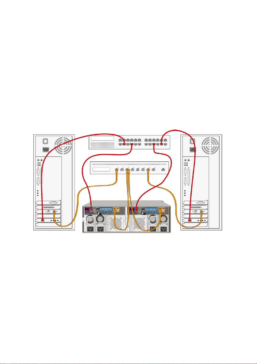
Figure 23: Management and 1GbE iSCSI connections on R2600fi
21
Important
For NAS setup, or configurations that use port trunking, cabling layout is very
important and should be carefully planned before making any connections to the
physical ports.
Important
The quality of cabling used for 10 GbE data connections is very important for
performance. 10 GbE connections must use Cat 6 or better cabling for the entire
data path. 1 GbE connections must use Cat 5e or better for the entire data path.
1GbE and 10GbE Data Path
1GbE connections:
Each Vess R2600 controller has four (4) RJ-45 data port connectors. Use at least Cat 5e or better
cabling. For a storage network (NAS or SAN), connect the data ports as follows:
1. Connect Ethernet cables between the HBA NIC or NIC in both hostPCs or servers and the
GbE network switch.
2. Connect an Ethernet cable between at least one GbE data port on the left RAIDcontroller
and the GbE network switch.
3. Connect an Ethernet cable between at least one GbE data port on the right RAIDcontroller
and the GbE network switch.
If you have multiple Vess R2600 subsystems, host PCs or servers, repeatsteps 1 through 3
as required.
Notice: GbE data ports on both RAID controller should be connected symmetrically so that NAS
failover can work properly.
22

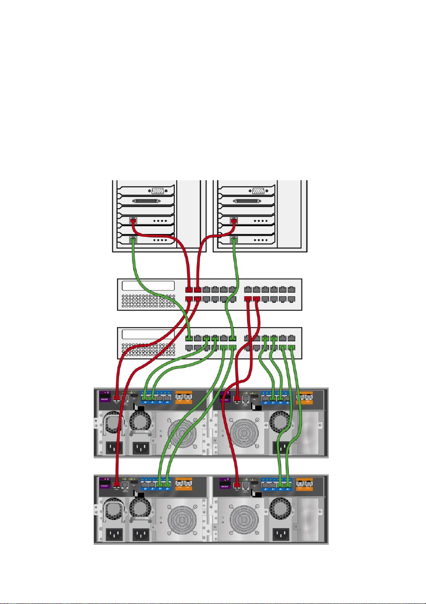
10GbE connections (R2600ti)
For a 10GbE storage network, use Cat 6 or better cabling to connect the two 10GbE ports on the
R2600ti controller:
1. Connect Ethernet cables between the HBA NIC or in both host PCs orservers and the 10
GbE network switch.
2. Connect an Ethernet cable between at least one 10 GbE data port on the left RAID
controller and the 10 GbE network switch.
3. Connect an Ethernet cable between at least one 10 GbE data port on the right RAID
controller and the 10 GbE network switch.
If you have multiple Vess R2600 subsystems, host PCs or servers, repeatsteps 1 through 3
as required.
Notice: 10 GbE data ports on both RAID controller should be connected symmetrically so that NAS
failover can work properly.
SAS JBOD EXPANSION
This arrangement requires:
• One (1) or more Vess J2600 expansion subsystems
• One (1) SFF-8088 to SFF-8088 SAS cable for each Vess J2600 expansion subsystem
CONFIGURING THE DATA PATH
Vess R2600 subsystems have one per RAID controller (1) SFF-8088 SAS Expansion Port
connector.
To expand the data path:
1. Attach one end of a SFF-8088 to SFF-8088 SAS cable to the SAS Expansion Port on the
Vess R2600 subsystem.
See “Figure 24: SAS JBOD expansion data connections”.
2. Attach the other end of the SFF-8088 to SFF-8088 SAS cable to the SAS IN Port on the
Vess J2600 subsystem.
If you have another Vess J2600 subsystem, attach one end of the SFF-8088 to SFF-8088
SAS cable to the SAS OUT Port of the first Vess J2600 to the SAS IN Port of the second
Vess J2600.
23
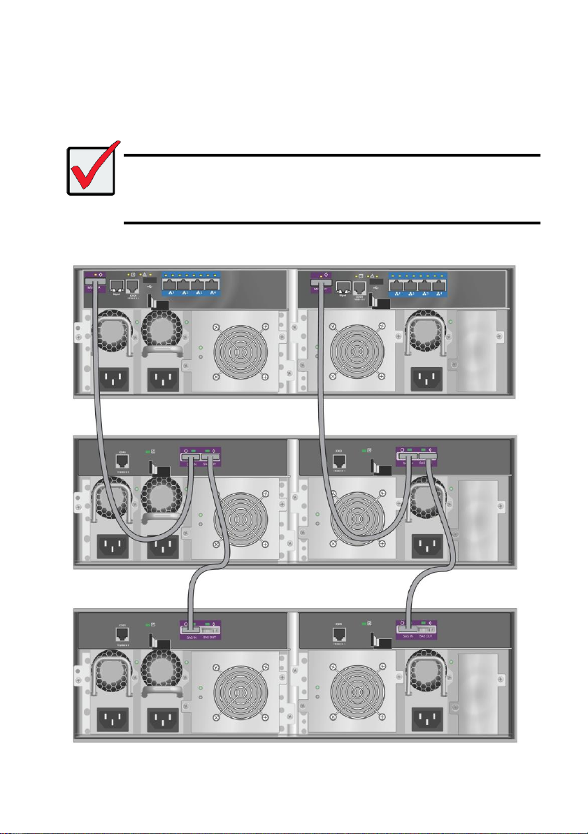
Important
Vess J2600 subsystems have one SAS IN port and one SAS OUT port. If you
connect them incorrectly, the Vess R2600 does not recognize the Vess J2600
subsystems.
For more information, see the Vess J2600 Product Manual on the CD that came
with the Vess J2600 subsystem.
CONFIGURING A MANAGEMENT PATH
The Vess R2600 controller manages the Vess J2600 subsystems. No additional management
connections are required for JBOD expansion.
Figure 24: SAS JBOD expansion data connections
24
TASK 5: CONNECTING THE POWER
Important
If you have a SAN, DAS, or Cascade with JBOD Expansion, always power on the
JBOD subsystems first.
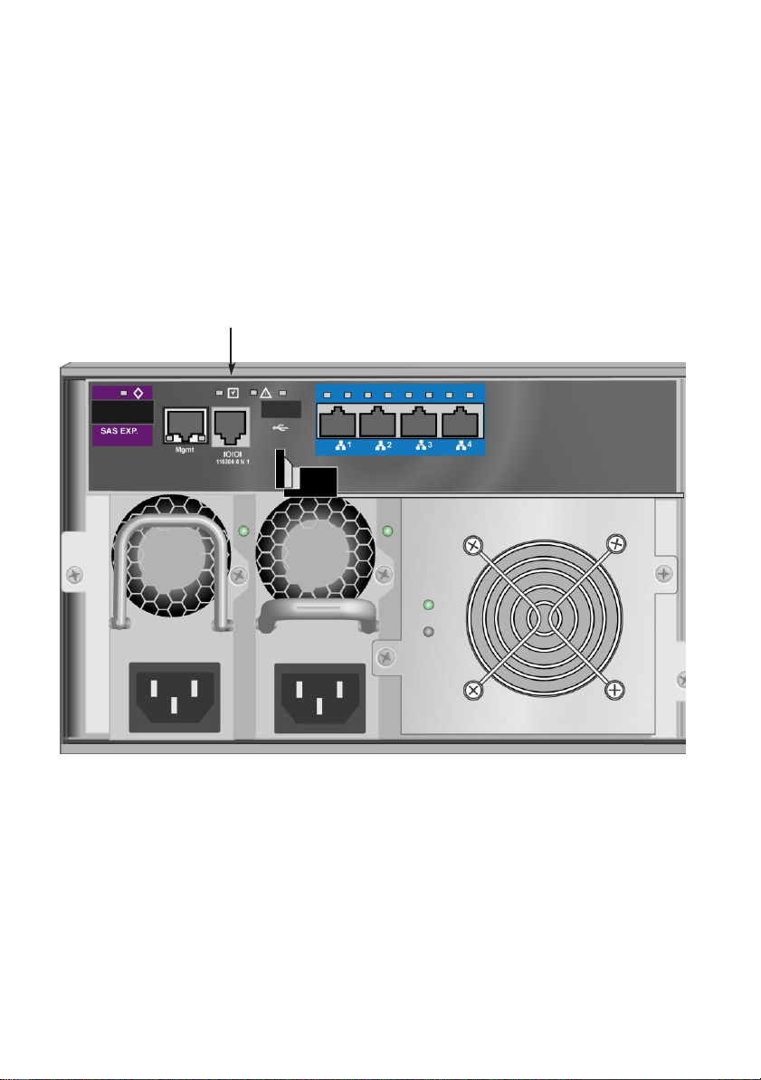
An optional fourth
power supply (PSU4)
can be installed in this
bay. See the product
manual for more in
formation on installing
and swapping power
supplies.
PSU1, PSU2 and PSU3 are installed on
both the Vess R2600 and Vess J2600.
Connect all power supplies to a suitable
power source.
Plug in the power cables on all power supplies.
The Vess R2600 and Vess J2600 enclosures can be equipped with up to four power supplies for
each unit. A minimum of two operating power supplies are required for normal function of both the
Vess R2600 and Vess J2600. The standard shipment includes three power supplies. Contact your
vendor for information on additional power supplies.
Figure 25: Vess R2600fiD rear panel power connections
25
Important
For information about installing or hot swapping power supplies, please see the
product manual.
Important
The Vess R2600 and Vess J2600 are equipped with LED indicators on the cooling
units and power supplies. Check these after powering the devices on to make sure
the cooling and power status for the enclosure is normal.
An optional fourth
power supply (PSU4)
is available.
PSU1, PSU2 and PSU3 are installed on
both the Vess R2600 and Vess J2600.
Connect all power supplies to a suitable
power source.
Figure 26: Vess J2600sD
26

With the power supplies connected, the system can now be powered on. Again, note that if your
Mute alarm button
Power button
OPAS LED
USB ports
Mute alarm LED
setup includes a SAN, DAS or cascade with Vess J2600 expansion, always power on the JBOD
subsystems first.
To power on the subsystem, press the Power button on the front left bracket facing (see illustration
below). Observe the LEDs on the right front bracket facing (see “Figure 28: Vess R2600 front panel
LED display on right side bracket”).
Figure 27: Vess R2600 front panel components, left side
FRONT PANEL LEDS
When boot-up is finished and the Vess R2600 subsystem is functioning normally:
• Power LEDs display blue continuously.
• Global Enclosure Status, and Global RAID Status LEDs display green continuously.
• Controller Activity LED flashes blue when there is controller activity.
• System Heartbeat LED blinks blue seven times in three seconds, goes dark for six seconds,
then repeats the pattern.
27
Global Enclosure Status
PSU 1 LED
PSU 2 LED
Cooling Unit 1 LEDs
BBU (top)
Cooling Unit Fan Status (bottom)
Power
Global RAID Status
Controller 1 Activity
Controller 2 Activity
System Heartbeat
Figure 28: Vess R2600 front panel LED display on right side bracket
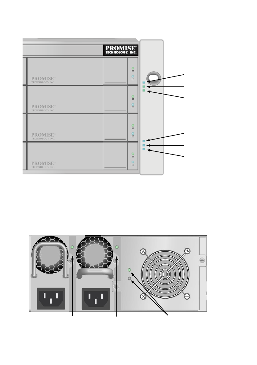
REAR PANEL PSU & COOLING FAN LEDS
The LEDs on the rear panel include LEDs on each cooling fan and each power supply. These LEDs
will light green to indicate normal operation. A red or amber LED indicates a problem or unit failure.
See the Product Manual for a complete description of LED indicators.
Figure 29: LEDs on Power Supply and Cooling Units
28
 Loading...