

Vess A2600, A2600S, A2200, A2200S Product Manual
A2600 A2200
Vess A2000 Series
Product Manual
Vess A2000 Series Product Manual
Warning
This is a Class A product. In a domestic environment this product
may cause radio interference in which case the user may be
required to take adequate measures.
Warning
The electronic components within the Vess enclosure are
sensitive to damage from Electro-Static Discharge (ESD). Observe
appropriate precautions at all times when handling the Vess or its
subassemblies.
Warning
Turn off the power and disconnect the power cord before
servicing this device.
ii
Promise Technologies
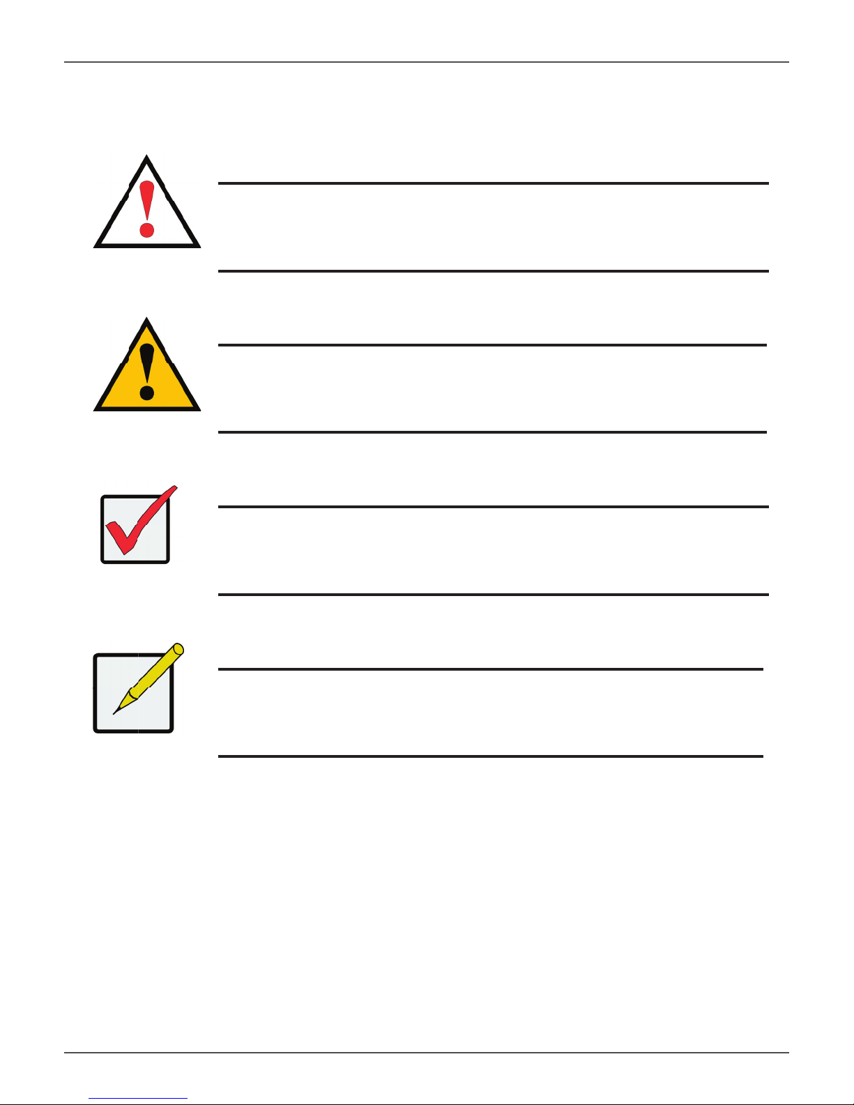
Also included are four levels of notices:
Warning
A Warning notifi es you of probable equipment damage or loss of data, or the
possibility of physical injury, and how to avoid them.
Caution
A Caution informs you of possible equipment damage or loss of data and how to
avoid them.
Important
An Important message calls attention to an essential step or point
required to complete a task, including things often missed.
Note
A Note provides helpful information such as hints or alternative ways of
doing a task.
iii

Vess A2000 Series Product Manual
CONTENTS
Introduction 1
VESS A2000 SERIES OVERVIEW 2
SYSTEM MANAGEMENT 2
SPECIFICATIONS 3
H
ARDWARE 4
FRONT PANEL HARDWARE 4
F
RONT PANEL LEDS 6
B
ACKPLATE HARDWARE 10
Hardware Setup 19
UNPACKING 20
M
OUNTING THE VESS A2000 IN A RACK 21
MOUNTING A 3U ENCLOSURE IN A RACK 22
M
OUNTING A 2U ENCLOSURE IN A RACK 25
INSTALLING DISK DRIVES 29
NUMBER OF DRIVES REQUIRED 29
MANAGEMENT PATH CONNECTIONS 37
Managing with WebPAM PROe 57
LOGGING INTO WEBPAM PROE 57
Q
UICK LINKS MENU 61
U
SING THE WEBPAM PROE INTERFACE 62
C
HOOSING A DISPLAY LANGUAGE 64
SUBSYSTEM MANAGEMENT 67
B
ACKGROUND ACTIVITIES 68
MANAGE BACKGROUND ACTIVITIES SETTINGS 69
M
EDIA PATROL 74
MANAGING ACTIVITY SCHEDULES 75
E
VENT LOGS 76
A
DMINISTRATIVE TOOLS 77
RESTORE FACTORY DEFAULT SETTINGS 77
USER MANAGEMENT 78
VIEWING USER INFORMATION 78
M
AKING USER SETTINGS 78
C
REATING A USER 80
V
IEW NETWORK SETTINGS 82
C
ONNECT THE POWER 39
P
OWER ON ENCLOSURE 41
POWER ON VESS A2600/A2600S 41
P
OWER ON VESS A2200/A2200S 44
C
ONNECT TO ISCSI STORAGE AREA NETWORK (SAN) 45
INSTALL RISER CARD IN VESS A2600/A2600S 47
I
NSTALL PCIE CARDS IN VESS A2200/A2200S 53
S
OFTWARE MANAGEMENT 82
E
MAIL SERVICE 87
P
ERFORMANCE MONITORING 89
CONTROLLERS 91
VIEW CONTROLLER INFORMATION 91
V
IEWING CONTROLLER STATISTICS 93
C
ONTROLLER SETTINGS 94
ENCLOSURES 95
ENCLOSURE INFORMATION 95
E
NCLOSURE TEMPERATURE SENSOR SETTINGS 96
B
UZZER SETTINGS 96
PHYSICAL DRIVES 97
D
ISK ARRAYS AND LOGICAL DRIVES 99
LOGICAL DRIVE MANAGEMENT 101
SPARE DRIVES 102
L
OGICAL DRIVE SUMMARY 103

Promise Technologies Contents
REATING A DISK ARRAY – EXPRESS (CLU) 129
Managing with CLU 104
USING THE CLU 106
A
CCESSING ONLINE HELP 110
E
XITING THE CLU 110
L
OGGING OUT OF THE CLI 110
L
OGGING BACK INTO THE CLI AND CLU 110
MANAGING THE SUBSYSTEM (CLU) 111
MAKING SUBSYSTEM SETTINGS (CLU) 111
R
UNNING MEDIA PATROL (CLU) 112
L
OCKING OR UNLOCKING THE SUBSYSTEM (CLU) 112
V
IEW SUBSYSTEM DATE AND TIME (CLU) 113
MANAGING THE RAID CONTROLLERS (CLU) 114
VIEWING CONTROLLER INFORMATION (CLU) 114
M
AKING CONTROLLER SETTINGS (CLU) 115
MANAGING THE ENCLOSURE (CLU) 117
VIEWING THE ENCLOSURES SUMMARY (CLU) 117
V
IEWING ENCLOSURE INFORMATION (CLU) 118
M
AKING ENCLOSURE SETTINGS (CLU) 118
V
IEWING POWER SUPPLY STATUS (CLU) 119
T
O VIEW THE STATUS OF THE POWER SUPPLIES: 119
V
IEWING COOLING UNIT STATUS (CLU) 119
V
IEWING TEMPERATURE SENSOR STATUS (CLU) 120
V
IEWING VOLTAGE SENSOR STATUS (CLU) 120
L
OCATING AN ENCLOSURE (CLU) 121
PHYSICAL DRIVE MANAGEMENT (CLU) 122
VIEWING A LIST OF PHYSICAL DRIVES (CLU) 122
M
AKING GLOBAL PHYSICAL DRIVE SETTINGS (CLU) 123
V
IEWING PHYSICAL DRIVE INFORMATION (CLU) 124
V
IEWING PHYSICAL DRIVE STATISTICS (CLU) 125
S
ETTING AN ALIAS (CLU) 125
L
OCATING A PHYSICAL DRIVE (CLU) 125
MANAGING DISK ARRAYS (CLU) 127
VIEWING A LIST OF DISK ARRAYS (CLU) 127
C
REATING A DISK ARRAY (CLU) 128
C
REATING A DISK ARRAY – AUTOMATIC (CLU) 128
C
C
REATING A DISK ARRAY – ADVANCED (CLU) 130
D
ELETING A DISK ARRAY (CLU) 132
M
AKING DISK ARRAY SETTINGS (CLU) 133
V
IEWING DISK ARRAY INFORMATION (CLU) 134
E
NABLING MEDIA PATROL, PDM, AND POWER MANAGEMENT ON A DISK ARRAY (CLU) 135
R
EBUILDING A DISK ARRAY (CLU) 136
R
UNNING MEDIA PATROL ON A DISK ARRAY (CLU) 136
R
UNNING PDM ON A DISK ARRAY (CLU) 137
R
UNNING TRANSITION ON A DISK ARRAY (CLU) 138
L
OCATING A DISK ARRAY (CLU) 138
MANAGING SPARE DRIVES (CLU) 139
VIEWING A LIST OF SPARE DRIVES (CLU) 139
C
REATING A SPARE DRIVE (CLU) 140
M
AKING SPARE DRIVE SETTINGS (CLU) 141
R
UNNING SPARE CHECK (CLU) 141
D
ELETING A SPARE DRIVE (CLU) 142
MANAGING LOGICAL DRIVES (CLU) 143
CREATING A LOGICAL DRIVE (CLU) 143
D
ELETING A LOGICAL DRIVE (CLU) 145
V
IEWING LOGICAL DRIVE INFORMATION (CLU) 146
V
IEWING LOGICAL DRIVE STATISTICS (CLU) 146
V
IEWING THE LOGICAL DRIVE CHECK TABLE (CLU) 147
M
AKING LOGICAL DRIVE SETTINGS (CLU) 147
I
NITIALIZING A LOGICAL DRIVE (CLU) 148
R
UNNING REDUNDANCY CHECK (CLU) 149
L
OCATING A LOGICAL DRIVE (CLU) 149
MANAGING BACKGROUND ACTIVITY (CLU) 150
VIEWING CURRENT BACKGROUND ACTIVITIES (CLU) 150
M
AKING BACKGROUND ACTIVITY SETTINGS (CLU) 151
WORKING WITH THE EVENT VIEWER (CLU) 152
VIEWING RUNTIME EVENTS (CLU) 153
C
LEARING RUNTIME EVENTS (CLU) 153
V
IEWING NVRAM EVENTS (CLU) 154
C
LEARING NVRAM EVENTS (CLU) 154

Vess A2000 Series Product Manual
MANAGING USERS (CLU) 155
VIEWING USER INFORMATION (CLU) 155
C
REATING A USER (CLU) 156
C
HANGING USER SETTINGS (CLU) 157
C
HANGING USER PASSWORD (CLU) 158
D
ELETING A USER (CLU) 159
SOFTWARE MANAGEMENT (CLU) 160
EMAIL SETTINGS (CLU) 160
SLP S
ETTINGS (CLU) 161
W
EB SERVER SETTINGS (CLU) 161
SNMP S
ETTINGS (CLU) 162
M
ANAGING SNMP TRAP SINKS (CLU) 163
CLEARING STATISTICS (CLU) 164
R
ESTORING FACTORY DEFAULTS (CLU) 165
B
UZZER 166
MAKING BUZZER SETTINGS 166
Maintenance 222
REPLACING A POWER SUPPLY 223
REMOVING THE OLD POWER SUPPLY 223
I
NSTALLING A NEW POWER SUPPLY 224
C
HANGE SYSTEM FAN VESS A2200/A2200S 225
Troubleshooting 227
HOW DO I KNOW WHEN A DRIVE IS FAILING? 228
CHECK DRIVE STATUS LEDS 228
A
NTICIPATING HARD DRIVE PROBLEMS 232
R
EBUILDING A DISK ARRAY 235
H
OW TO REBUILD A DISK ARRAY 236
HOW TO SAVE A SERVICE REPORT 238
THE ALARM BUZZER IS SOUNDING, WHAT DOES THIS MEAN? 240
R
EINSTALLING THE OPERATING SYSTEM 242
FAQ 247
S
ILENCING THE BUZZER 166
Managing with the CLI 167
OPENING THE CLI ON WINDOWS 167
O
PENING THE CLI ON LINUX 168
TABLE OF SUPPORTED COMMANDS 169
N
OTES AND CONVENTIONS 171

Promise Technologies Introduction
INTRODUCTION
The Vess A2000 NVR storage appliance is specially engineered for medium to large scale IP video surveillance
deployment. The Vess A2000 Series is ideally suited for continuous surveillance in banks, malls, casinos, factories,
warehouses, and similarly sized commercial, residential, governmental or private enterprises. The subsystems are
capable of continuous recording and playback operation without dropping frames for networked installations of
32 to 100 High-Defi nition IP cameras.
Vess A2000 NVR storage appliances are available with your choice of Windows or Linux operating systems, a
Video Management Software suite, and disk drives in order to streamline the installation and integration process.
The Vess A2000 Series subsystems are stand-alone devices with internal RAID storage, eliminating need for
additional servers, controllers, separate enclosures etc. The Vess A2000 Series uses the renowned PROMISE
RAID engine for maximum reliability, all drive bays are hot-swappable, and models are available with redundant
power supplies to ensure data safety and uninterrupted operation.
The Vess A2000 Series models include PCIe slots for added fl exibility. The PCIe slots are suitable for video
graphics cards, video encode/decode cards, RAID cards, or other useful function available on the PCIe platform.
1

Vess A2000 Series Product Manual
VESS A2000 SERIES OVERVIEW
SYSTEM MANAGEMENT
The Vess A2000 Series are shipped with either Windows Embedded Standard 7 Runtime (WS7P) or Linux
CentOS 6.3 operating systems depending on customer preference.
MANAGEMENT INTERFACES
• Browser-based management with WebPAM PROe
• Command Line Interface (CLI)
• Command Line Utility (CLU)
2

Promise Technologies Introduction
SPECIFICATIONS
Vess Model A2200/A2200s A2600/A2600s
Form factor 2U, 19” rack mount or desktop 3U, 19” rack mount
Function NVR server NVR server
Operating system Linux or Windows Linux or Windows
Drives supported Six 3.5” SATA (3Gb/s or 6Gb/s)* Sixteen 3.5” SATA (3Gb/s or 6Gb/s)*
Storage Expansion
(iSCSI & JBOD)
RAID support 0, 1, 1E, 3, 5, 6, 10, 30, 50 0, 1, 1E, 3, 5, 6, 10, 30, 50, 60
RAID stripe size 64K, 128K, 256K, 512K, 1MB 64K, 128K, 256K, 512K, 1MB
Max. LUNs 256/system 32/array 256/system 32/array
Hot swap drives Yes Yes
Controller Single Single
Graphics
Memory 4GB DDR (up to 16 GB) 8GB DDR (up to 16 GB)
Processor
PSU 450W single or 500W N+1 450W single or 500W N+1
Ivy Bridge Intel® HD Graphics
Intel® Core™ i3-3225 @ 3.30GHz
Up to 118 HD Up to 128 HD
Ivy Bridge Intel® HD Graphics
4000
Dual-core 4-thread
Intel® Xeon® Processor E3-1245V2
@ 3.4GHz Quad-core 8-thread
P4000
System fans Swappable fan Swappable fan
Dimensions 44 x 40 x 88 cm 45 x 46 x 140
Weight
*Can use 6 Gb/s hard disk drive but they will run at 3 Gb/s
10.4kg(22.9 lbs) w/o drives, 14.9kg
(32.8lbs) w/drives
3
15.9kg(35.1 lbs) w/o drives, 27.9kg
(61.5lbs) w/drives

Vess A2000 Series Product Manual
HARDWARE
The following section provides a summary of the front and back panel hardware features of the Vess A2000
Series enclosures.
FRONT PANEL HARDWARE
The front panel of Vess A2000 Series enclosures provide access to drives carriers. Some A2000 Series units are
shipped with secure covers to protect the drive carriers from being unintentionally removed.
For all Vess A2000 Series enclosures, defective drives can be replaced without interruption of data availability to
the host computer. If so confi gured, a hot spare drive will automatically replace a failed drive, securing the fault-
tolerant integrity of the logical drive. The self-contained hardware-based RAID logical drive provides maximum
performance in a compact external enclosure.
4
Promise Technologies Introduction
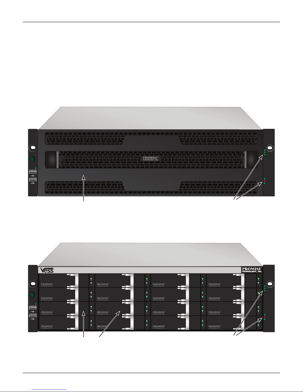
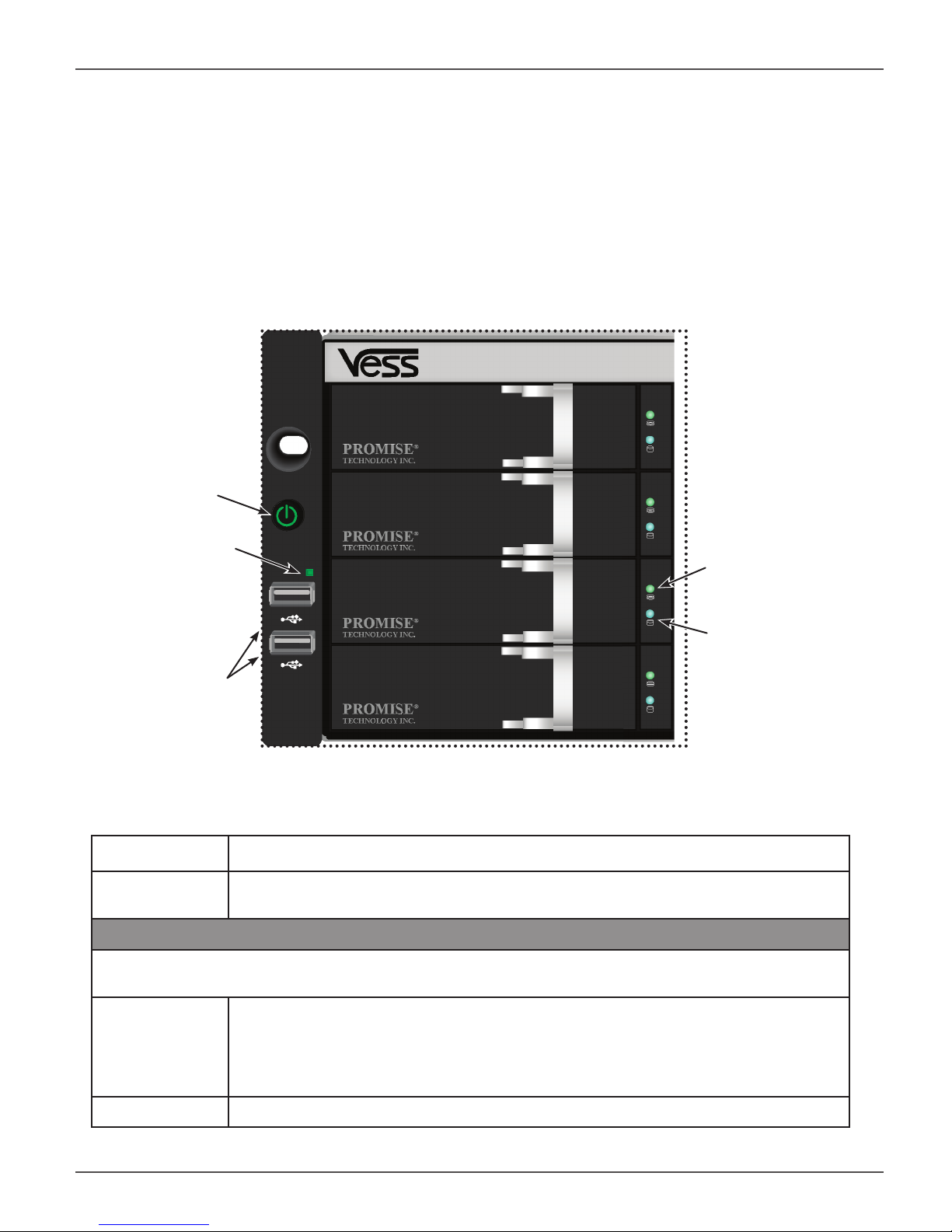
FRONT OF VESS A2600/A2600S
The Vess A2600/A2600s enclosure features handles on each side used to secure the enclosure to an equipment
rack. The system power button and two USB ports are located on the left side, and most of the front LED
indicators are located on the right side.
Vess A2600s/A2600 front view with secure cover
cover
Vess A2600s/A2600 front view
Drive carriers
Power and
Status LEDs
Power and
Status LEDs
5
Vess A2000 Series Product Manual
FRONT PANEL LEDS
Descriptions of the LED behavior and function for Vess A2000 Series enclosures.
VESS A2600/A2600S FRONT PANEL LED
Vess A2600/A2600s Front Panel LEDs - Left side
Power button
OPAS LED
USB ports
Left side LED behavior for the Vess A2600/A2600s
Drive Status
one LED per carrier
Activity
one LED per carrier
LED Description
OPAS USB Lights GREEN if an OPAS device (USB disk) is detected, RED if the OPAS operation
has failed, blinks GREEN when an OPAS operation is in progress.
Drive Carrier LEDs (located on all drive carriers)
Drive Status Each drive carrier has two LEDs on the right side of the front, the Drive Status LED lo-
cated above the Activity LED. The Drive Status LED displays GREEN when a drive is
confi gured and working properly. When the lights are RED the HDD requires manual
replacement. ORANGE indicates background RAID activity on this particular HDD, no
user action is required.
Drive Activity Flashes BLUE during drive activity.
6
Promise Technologies Introduction
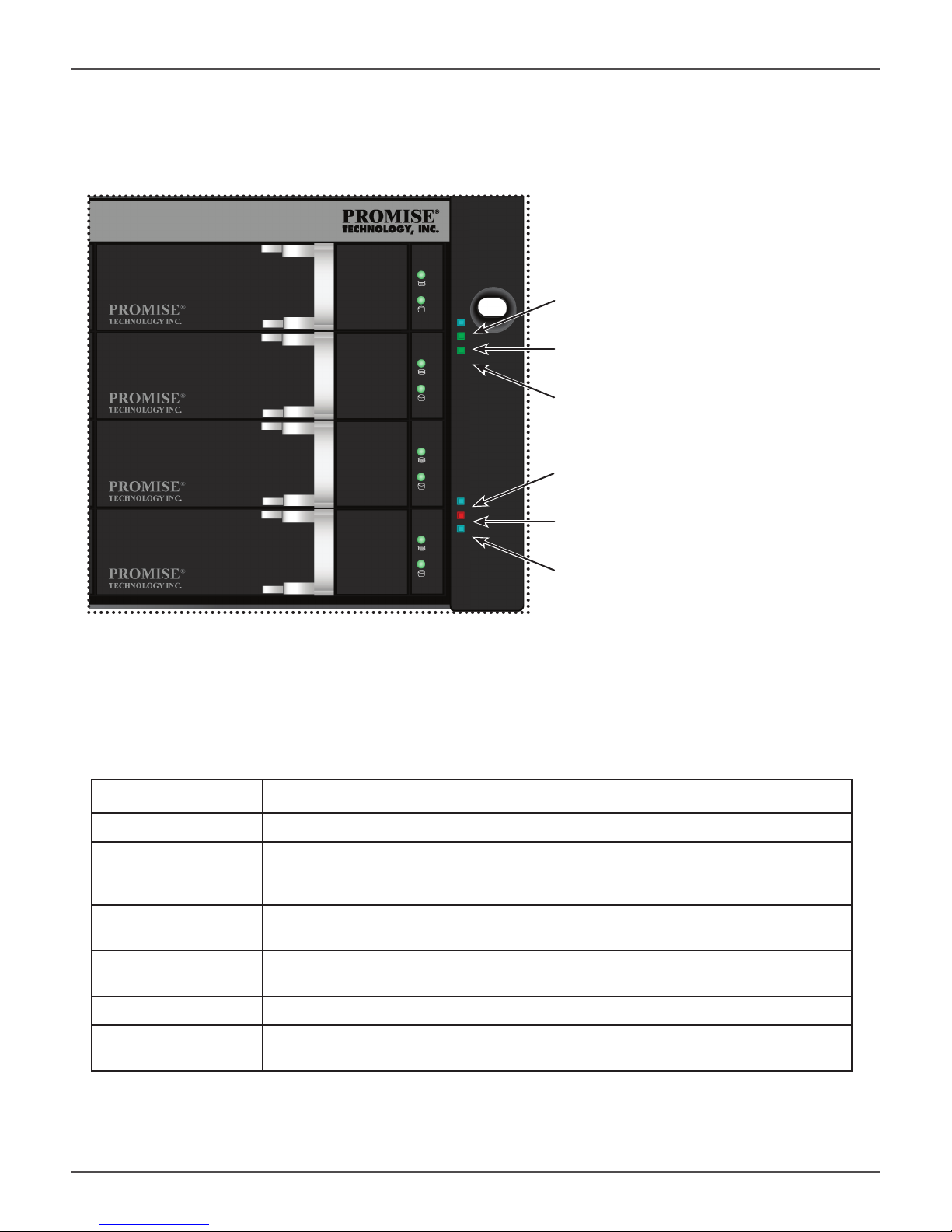
Vess A2600/A2600s Front Panel LEDs - Right side
Power
System Status
Global RAID Status
Global HDD Activity
Recording
System Heartbeat
Right side LED behavior for the Vess A2600/A2600s
LED Description
Power Lights BLUE to indicate the system is powered on. Blinks BLUE in shutdown mode.
System Status Lights GREEN when healthy, RED if there is a critical problem (LD offl ine, fan mal-
function, voltage out of range, system temperature alert), blinks RED for HDD high
temperature alert remains dark when not ready.
Global RAID Status Lights GREEN when healthy or RED if any RAID volume is offl ine, ORANGE for
critical state of any logical drive.
Global HDD Activity Blinks BLUE to indicate one or more drives are being accessed, remains dark when
no drives are being accessed.
Recording RED indicates application running.
System Heartbeat Blinks BLUE slowly at regular intervals to indicate the fi rmware and software are
operating normally.
7
Vess A2000 Series Product Manual
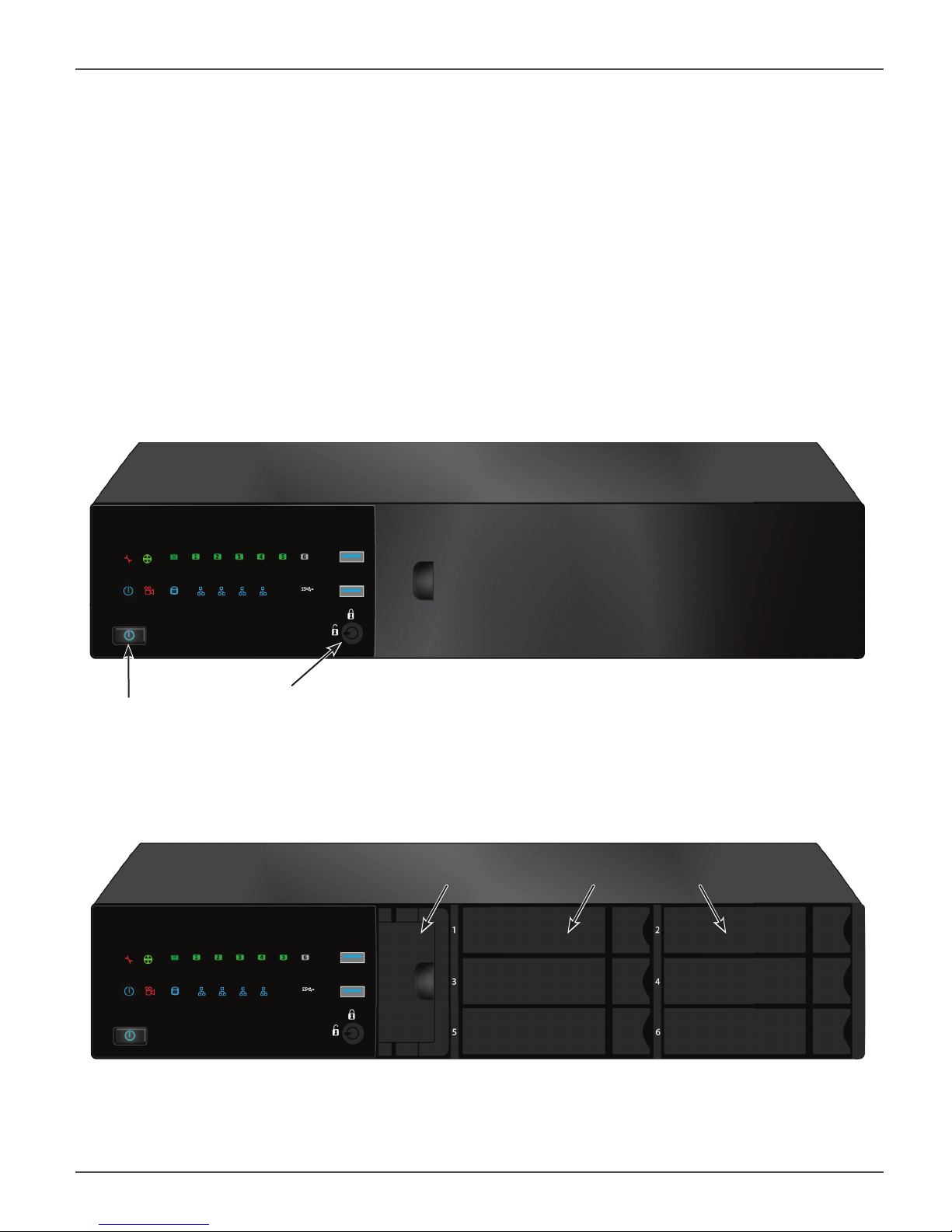
FRONT OF VESS A2200/A2200S
The Vess A2200 and Vess A2200s are shipped with a lockable front secure cover to provide physical security
for installed hard disks and cooling unit module. Use the tubular key shipped with the unit to lock or unlock this
cover to access the six hard drive carrier trays and removable cooling unit in front.
The left panel contains the power button, various LEDs, USB ports and the tubular lock.
Vess A2200s/A2200 front view with secure cover
Secure
Power button
panel lock
Vess A2200s/A2200 front view with cover removed
System Fan
module
Hard drive carriers
8
Promise Technologies Introduction
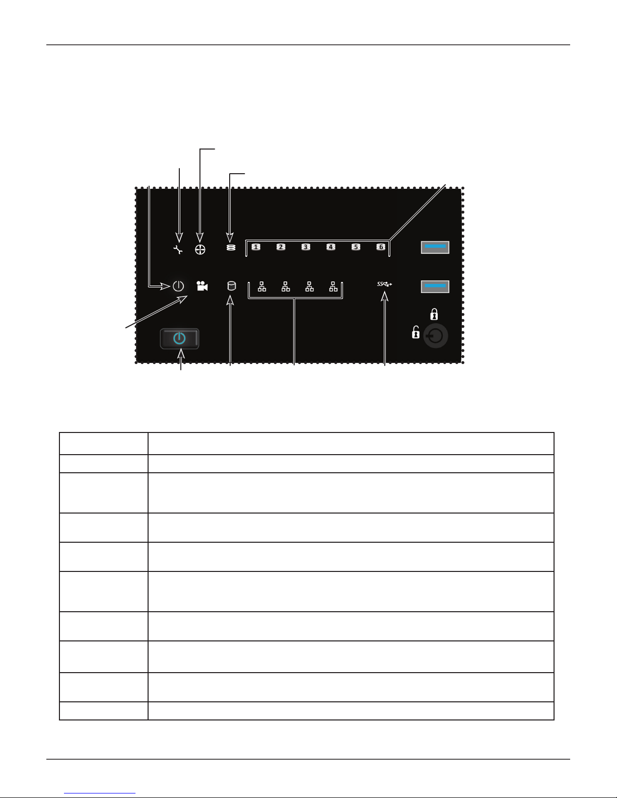
VESS A2200/A2200S FRONT PANEL LED
Vess A2200/2200s Le panel LED
System
Fan Status
Status
Power
Global RAID Status
Recording
Power
button
HDD
Activ-
Network Link/Activ-
ity
ity
Front panel LED behavior for Vess A2200/A2200s system:
HDD Status LEDs
OPAS
USB
LED Description
Power Lights BLUE to indicate the system is powered on. Blinks BLUE in shutdown mode.
System Status Lights GREEN when healthy, RED if there is a critical problem (LD offl ine, fan malfunc-
tion, voltage out of range, system temperature alert), blinks RED for HDD high temperature alert remains dark when not ready.
Global RAID
Status
Global HDD
Activity
HDD Status One LED for each HDD carrier. Each LED lights GREEN when healthy, RED if the RAID
Fan Status Lights GREEN when healthy, RED indicates a fan in the CPU module is not operating in
Network One LED for each LAN port. Lights BLUE to indicate a valid link, blinks BLUE to indicate
OPAS USB Lights GREEN if an OPAS device (USB disk) is detected, RED if the OPAS operation has
Recording RED indicates application running.
Lights GREEN when healthy or RED if any RAID volume is offl ine, ORANGE for critical
state of any logical drive.
Blinks BLUE to indicate one or more drives are being accessed, remains dark when no
drives are being accessed.
member is offl ine or there is a physical disk error, ORANGE indicates the drive is rebuilding, and a dark LED indicates either no drive is installed or the drive is not confi gured.
normal range, ORANGE indicates the CPU fan module is not present.
activity on the port.
failed, blinks GREEN when an OPAS log dump is in progress.
9
Vess A2000 Series Product Manual
BACKPLATE HARDWARE
The backplane of the Vess A2000 Series enclosure provides access to the power supply (or power supplies),
local management connection (via USB keyboard and VGA or HDMI monitor port), iSCSI (Ethernet) data ports,
some units also provide I/O connections for audio sensor and alarm systems. The A2600/A2600s backplate
includes the system fan.
VESS A2600/A2600S BACKPLATE OVERVIEW
The Vess A2600 enclosure features 3 hot-swappable power supplies (PSU) while the Vess A2600s enclosure
is equipped with a single PSU that is not hot-swappable. Both enclosures are available with the alarm (RS-422)
and audio (RS-485) I/O terminal block connection option. For detail on the control panel connections and LED
indicators, please see the relevant sections below.
Note
The Vess A2600s featuring a single power supply will not be available for general
distribution. This model will be made available by special order only.
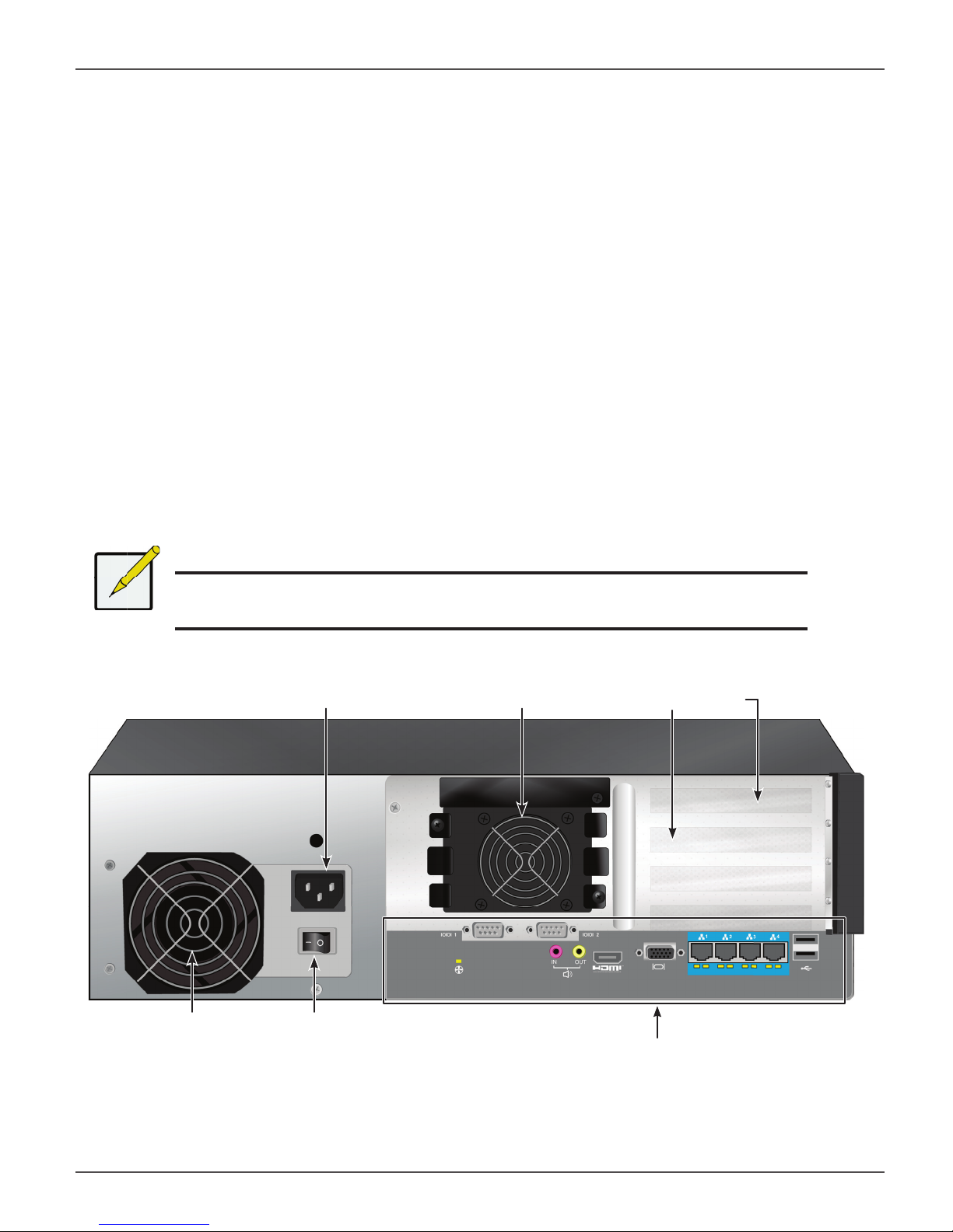
Vess A2600s rear view
Power insert
System fan
Raiser card slots
PSU
fan
Power
switch
Ports and LED indicators on control panel
10

Promise Technologies Introduction
Vess A2600s with op onal sensor/alarm IO ports rear view
PSU fan
Power insert
Power switch
pictured in “ON” position
System fan
Ports and LED indicators on control panel
Raiser card slots
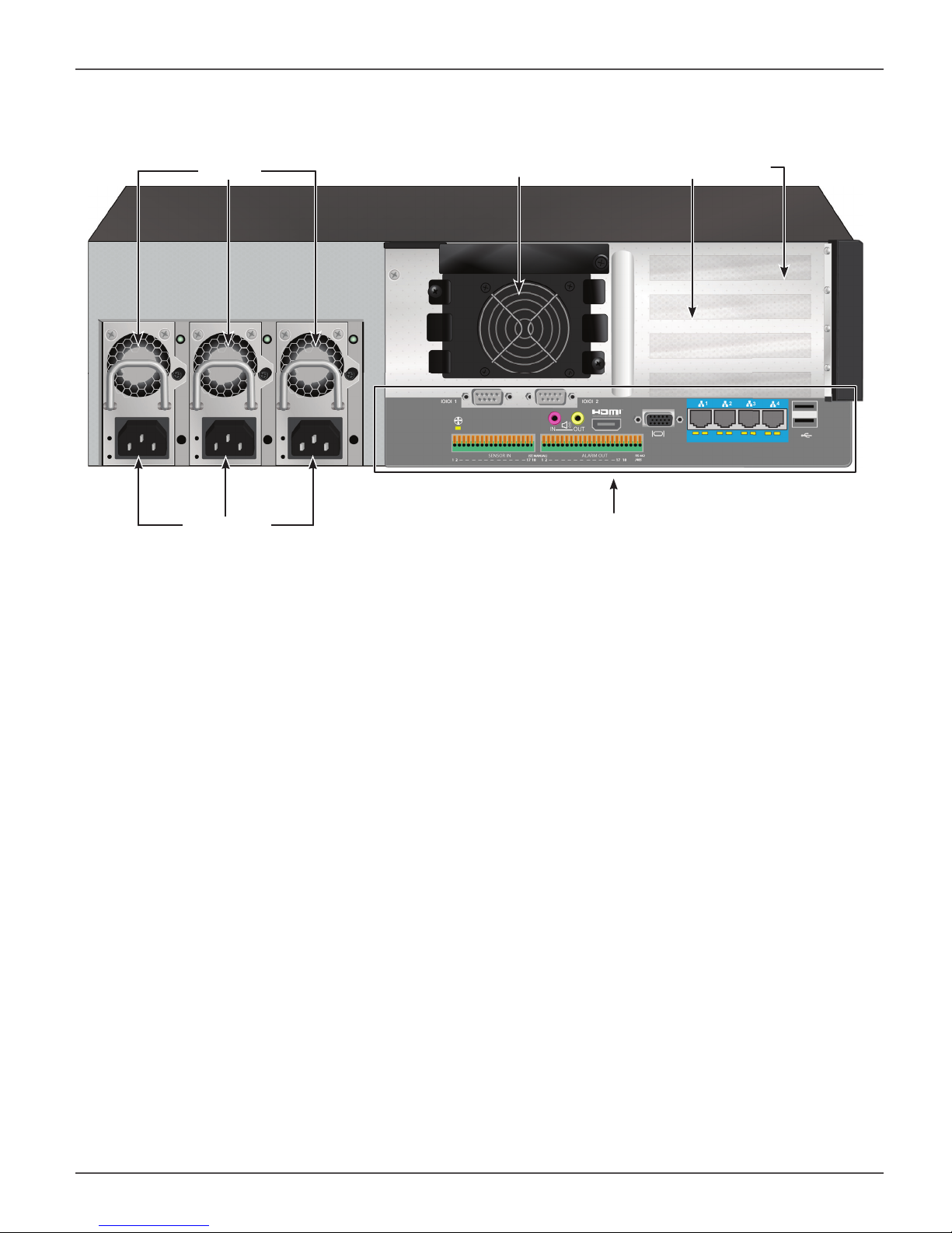
Vess A2600 rear view
PSU fans
Power inserts
System fan
Ports and LED indicators on control panel
Raiser card slots
11
Vess A2000 Series Product Manual
Vess A2600 with op onal sensor/alarm IO ports rear view
PSU fans
Power inserts
System fan
Ports and LED indicators on control panel
Raiser card slots
12
Promise Technologies Introduction
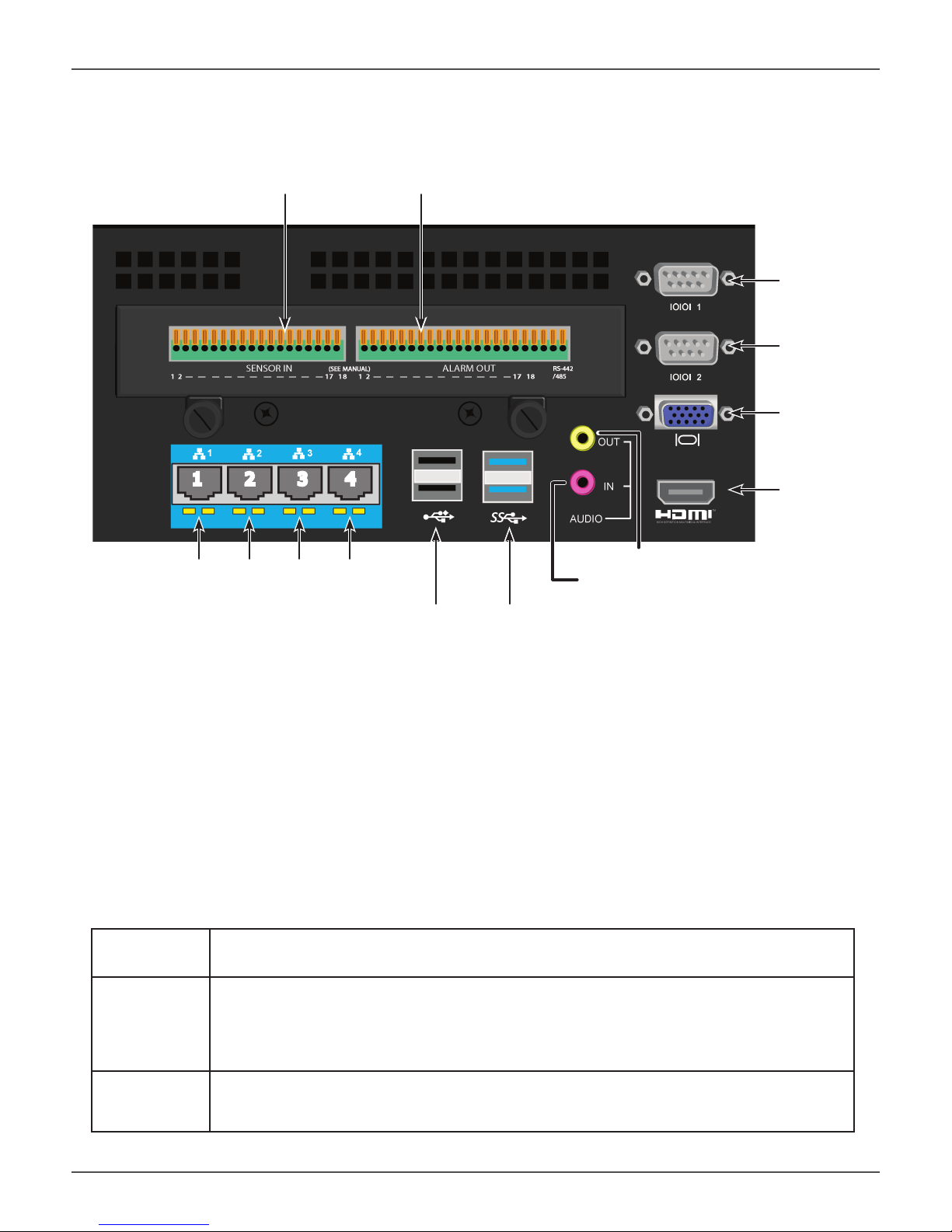
The Vess A2600/A2600s data and management connections are located on the backplate below the cooling
unit and to the right of the PSU (PSUs).
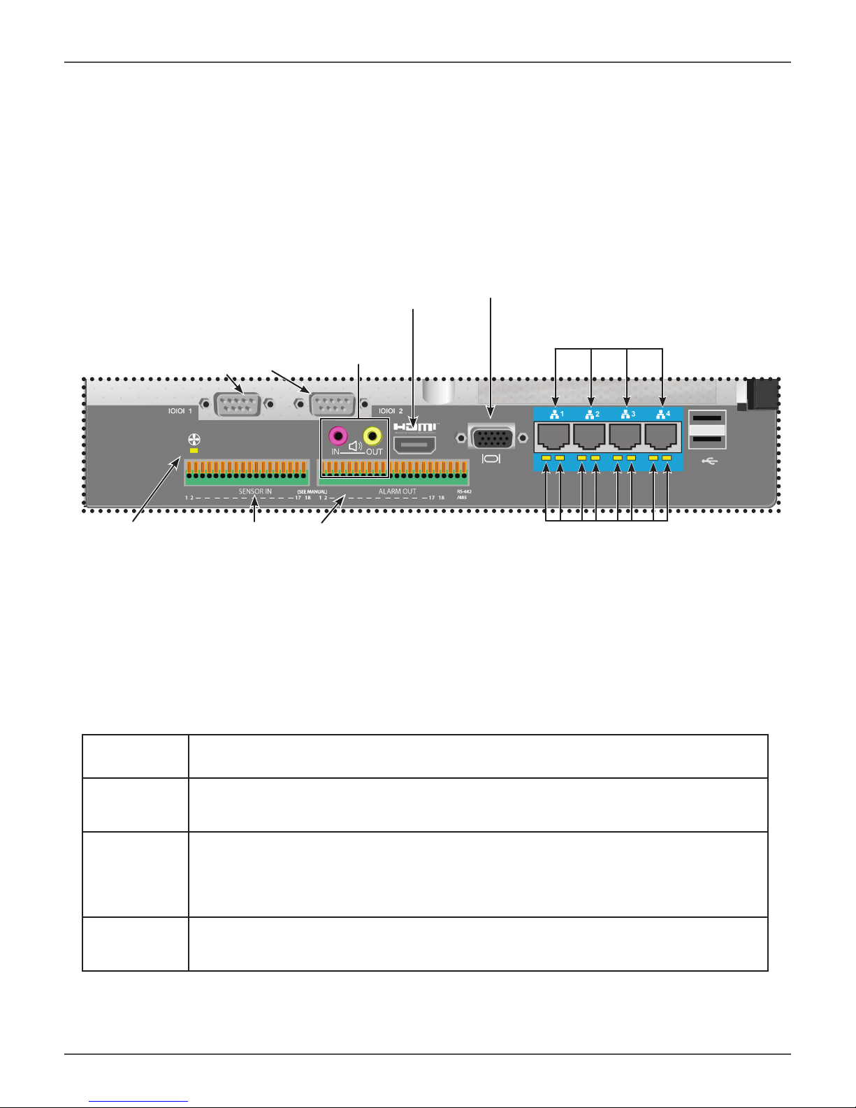
Vess A2600/A2600s backplate connec ons and LED indicators
HDMI port
VGA port
Gigabit Ethernet ports
RS-232 Ports
Audio I/O ports
1 2
Fan Status LED
RS-422/RS-485 connections
Gigabit Ethernet port LEDs
VESS A2600 BACKPLATE LED INDICATORS
The LEDs on the backplate include LEDs for System Fan and Ethernet data ports. The A2600 also has an LED
on each of the hot-swappable PSUs.
LED Description
System Fan A steady GREEN LED indicates normal fan function. A RED LED indicates fan failure, the
fan must be replaced.
Ethernet
Link/Act and
Speed
(Vess A2600)
The LED located below each port, on the left side, lights GREEN when connected, fl ashes
GREEN when there is activity on the port and remains dark no connection has been established. The LED on the lower right of each port indicates connection speed, GREEN is 100
Mbps, ORANGE is 1000 Mbps.
PSU
The power supply LEDs on the A2600 light GREEN to indicate normal operation. A RED
LED indicates a problem or unit failure.
13

Vess A2000 Series Product Manual
VESS A2600 BACKPLATE CONNECTIONS
Access to physical data and management connections are located on the backplate of the Vess A2600/A2600s
including the optional I/O connections for sensor and alarm systems.
Feature Description
HDMI Provides video out connection for HDMI enabled monitors used to view the management
interface using CLI, CLU or WebPAM PROe.
VGA This is also used for a video out connection for VGA monitors, it is also used to view the
management interface using CLI, CLU or WebPAM PROe.
USB Use to connect to a USB keyboard for managing the Vess A2000 Series, or use it to trans-
fer data to or from a USB memory device.
RS-232
Port 1
RS-232
Port 2
Audio In Use for input from a peripheral audio device, such as a microphone. Plug-In Power micro-
Audio Out Use for output (line out) peripheral audio device (speakers, for example).
RS-422/
RS-485
This is used for control line connection to an uninterruptible power supply (UPS).
Use this to connect to analog cameras via the analog camera input cable.
Note: This connector cannot be used at the same time as the RS-422/485 connector.
phones are supported.
Use this to connect to analog cameras via the analog camera input cable.
Note: This connector cannot be used at the same time as the RS-232 connector.
Note
Analog camera connections are available through either the RS-232 Port 2 or the
RS-422/RS-485 connections. These cannot be used simultaneously.
14

Promise Technologies Introduction
VESS A2200/A2200S BACKPLATE OVERVIEW
The Vess A2200 enclosure features 3 hot-swappable power supplies (PSU) while the Vess A2200s enclosure is
equipped with a single PSU that is not hot-swappable. Both enclosures are available with the alarm sensor (RS-
422) and audio (RS-485) I/O terminal block connection option. For detail on the control panel connections and
LED indicators, please see the relevant sections below.
Vess A2200s rear view
Covers for PCIe card access
Power insert
RS-422 / RS-485 ports
Sensor input / Alarm output
PSU fan
Power switch
USB ports
USB 2.0 on left
USB 3.0 on right
Network ports
and LED indicators
Audio In/Out HDMI port
Note
The Vess A2200s featuring a single power supply will not be available for general
distribution. This model will be made available by special order only.
15
Vess A2000 Series Product Manual
The Vess A2200 is identical to the Vess A2200s except that it includes an N+1 power supply arrangement.
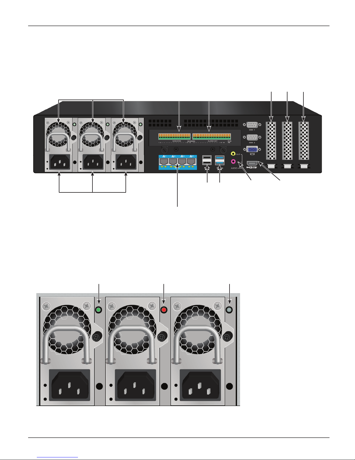
Vess A2200 rear view
Covers for PCIe card access
PSU fans
RS-422 / RS-485 ports
Sensor input / Alarm output
Power inserts
Network ports
and LED indicators
Vess A2200 and Vess A2600 Power Supply Status LEDs
Green = normal Red = problem
USB ports
USB 2.0 on left
USB 3.0 on right
Dark = no power or PSU not installed
Audio In/Out HDMI port
16
Promise Technologies Introduction
Ports and LEDs on rear panel of Vess A2200/A2200s
RS-422 / RS-485 ports
Sensor input / Alarm output
RS-232
Port 1
Port 2
VGA port
1 2 3 4
Network ports and LED indicators
Audio Out (top, yellow)
Audio In (bottom, pink)
USB Ports
Two USB 2.0 / Two USB 3.0
HDMI port
VESS A2200 BACKPLATE LED INDICATORS
The LEDs on the backplate include LEDs for System Fan and Ethernet data ports. The Vess A2200 also has an
LED on each of the hot-swappable PSUs.
LED Description
Ethernet
Link/Act and
Speed
(Vess A2600)
The LED located below each port, on the left side, lights GREEN when connected, fl ashes
GREEN when there is activity on the port and remains dark no connection has been established. The LED on the lower right of each port indicates connection speed, GREEN is 100
Mbps, ORANGE is 1000 Mbps.
PSU
The power supply LEDs on the A2600 light GREEN to indicate normal operation. A RED
LED indicates a problem or unit failure.
17

Vess A2000 Series Product Manual
VESS A2200 BACKPLATE CONNECTIONS
Access to physical data and management connections are located on the backplate of the Vess A2200/A2200s
including the optional I/O connections for sensor and alarm systems.
Feature Description
HDMI Provides video out connection for HDMI enabled monitors used to view the management
interface using CLI, CLU or WebPAM PROe.
VGA This is also used for a video out connection for VGA monitors, it is also used to view the
management interface using CLI, CLU or WebPAM PROe.
USB The backplate of the A2200/A2200s features two USB 2.0 and two USB 3.0 ports. Use to
connect to a USB keyboard for managing the Vess A2000 Series, or use it to transfer data
to or from a USB memory device.
RS-232
Port 1
This is used for control line connection to an uninterruptible power supply (UPS).
RS-232
Port 2
Audio In Use for input from a peripheral audio device, such as a microphone. Plug-In Power micro-
Audio Out Use for output (line out) peripheral audio device (speakers, for example).
RS-422/
RS-485
Use this to connect to analog cameras via the analog camera input cable.
Note: This connector cannot be used at the same time as the RS-422/485 connector.
phones are supported.
Use this to connect to analog cameras via the analog camera input cable.
Note: This connector cannot be used at the same time as the RS-232 connector.
Note
Analog camera connections are available through either the RS-232 Port 2 or the
RS-422/RS-485 connections. These cannot be used simultaneously.
18

Promise Technologies Hardware Setup
HARDWARE SETUP
This chapter presents the basics on unpacking, setting up hardware for the Vess A2600/A2600s and Vess
A2200/2200s. Hardware installation includes installing the unit in an equipment rack, connecting the power,
making network, data and management connection to the device, and installing hard drives.
The sections in Hardware Setup include the following:
• “Unpacking”
• “Mounting the Vess A2000 in a rack”
• “Mounting a 2U enclosure in a Rack” (Vess A2200/Vess A2200s)
• “Mounting a 3U enclosure in a Rack” (Vess A2600/Vess A2600s)
• “Installing Disk Drives”
• “Number of Drives Required”
• “Remove Drive Security Cover (Vess A2200/A2200s)”
• “Drive Slot Numbering”
• “Vess A2600 drive carriers”
• “Vess A2200 drive carriers”
• “Management Path Connections”
• “Connect the Power”
• “Power On Enclosure”
• “Power On Vess A2600/A2600s”
• “Power On Vess A2200/A2200s”
• “Connect to iSCSI Storage Area Network (SAN)”
• “Install Riser Card in Vess A2600/A2600s”
• “Install PCIe cards in Vess A2200/A2200s”
19

Vess A2000 Series Product Manual
UNPACKING
Note
The Vess A2000 Series can accommodate SATA (3Gbps/6Gbps) hard
drives.
PACKING LIST
The Vess A2600/A2600s box contains the following items:
• Vess A2600s or A2600
Quick Start Guide
•
(Note that the Product Manual is found on the desktop
after booting up and logging in)
• Screws for disk drives (70 pieces for 16-bay)
The Vess A2200/A2200s box contains the following items:
• Vess A2200s or A2200
Quick Start Guide
•
Manual and this Quick Start Guide, in PDF format,
are found on the desktop after booting up and logging
in)
printed
printed (Note that the Product
• 1.5m (4.9 ft) Power cords
(3 cords for A2600 3 PSU ,
1 cord for A2600s 1 PSU )
• Sliding rail assembly for rack mounting*
• Front panel bezel cover*
• 1.5m (4.9 ft) Power cords
(3 cords for A2200 3 PSU ,
1 cord for 1 PSU A2200s)
Sliding rail assembly for rack
•
mounting*
• Screws for disk drives (40 pieces for 6 bays)
* These items might be an optional feature in your region. Please contact your sales representative to learn
whether this is included or an option for your Vess A2000 Series enclosure.
20
Promise Technologies Hardware Setup
MOUNTING THE VESS A2000 IN A RACK
The instructions here apply to the Vess A2000 Series. Follow the instructions according to the form factor of
the Vess enclosure you are installing.
Cautions
• Do not populate any unit with hard drives until it has been securely
installed in the rack.
• At least two persons are required to safely lift, place, and attach the
Vess unit into a rack system.
• Do not lift or move the Vess unit by the handles, power supplies or
the controller units. Hold the system itself.
• Do not install the Vess unit into a rack without rails to support the
system.
• Only a qualifi ed technician who is familiar with the installation
procedure should mount and install the Vess unit.
• Mount the rails to the rack using the appropriate screws and fl ange
nuts, fully tightened, at each end of the rail.
• Do not load the rails unless they are installed with screws as
instructed.
• The rails available for the PROMISE Vess unit are designed to safely
support that PROMISE Vess unit when properly installed. Additional
loading on the rails is at the customer’s risk.
• PROMISE Technology, Inc. cannot guarantee that the mounting rails
will support your PROMISE Vess unit unless you install them as
instructed.
Note
To lighten the Vess enclosure, you can remove the power supplies.
Replace the power supplies after the Vess unit is mounted in your
rack.
Note
Please refer to the Quick Installation Guide included with the
mounting rails for more detailed rack installation instructions.
21
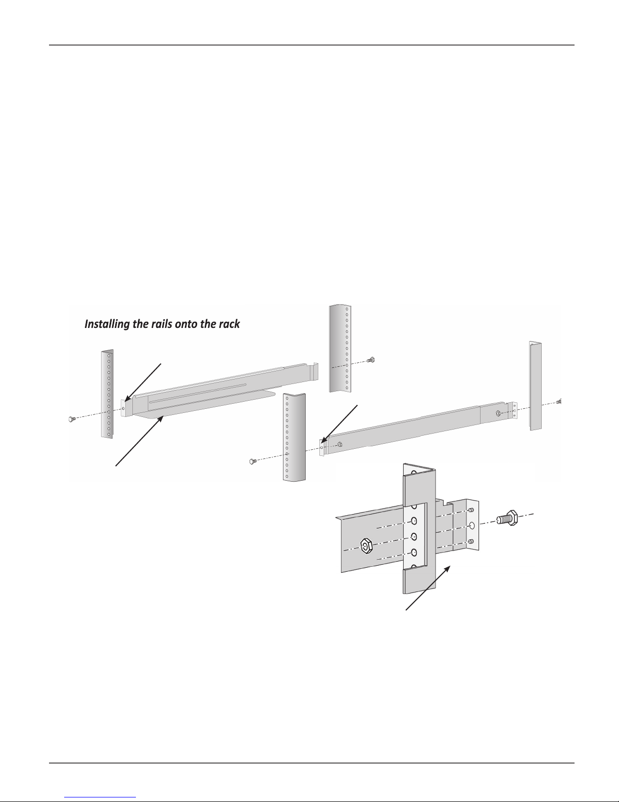
Installing the rails onto the rack
Vess A2000 Series Product Manual
MOUNTING A 3U ENCLOSURE IN A RACK
To install the Vess into a rack with the supplied mounting rails:
1. Check the fi t of the mounting rails in your rack system.
2. Adjust the length of the mounting rails as needed.
• The rear rail slides inside the front rail. The rail halves are riveted together and use no adjustment
screws.
• The front-left and front-right mounting rail ends are labeled.
• Be sure the front rail support is on the bottom facing inward.
Installing the rails onto the rack
Front left label
Front right label
Support fl ange on the front
end of each rail
Guide pins on rails align with holes in the rack post
• All rail ends, front and rear, attach at the outside of the rack posts.
• The guide pins at the rail ends align with the holes in the rack posts.
• Use the attaching screws and fl ange nuts from your rack system. Tighten the screws and nuts according
to instructions for your rack system.
22
Promise Technologies Hardware Setup
Rail ends a ach to the outside of each post
Rail ends attach on
the outside of the
front and rear rack
posts
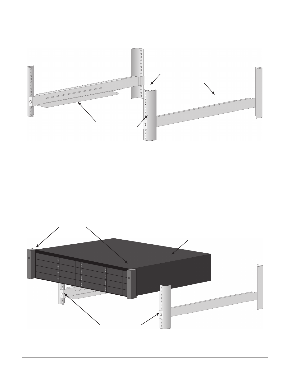
3. Place the Vess onto the rails.
• At least two persons are required to safely lift the system.
• Lift the Vess itself. Do not lift the system by its handles.
Placing the Vess system onto the rack rails
Handles
Vess system
Rails installed and
tightened
23
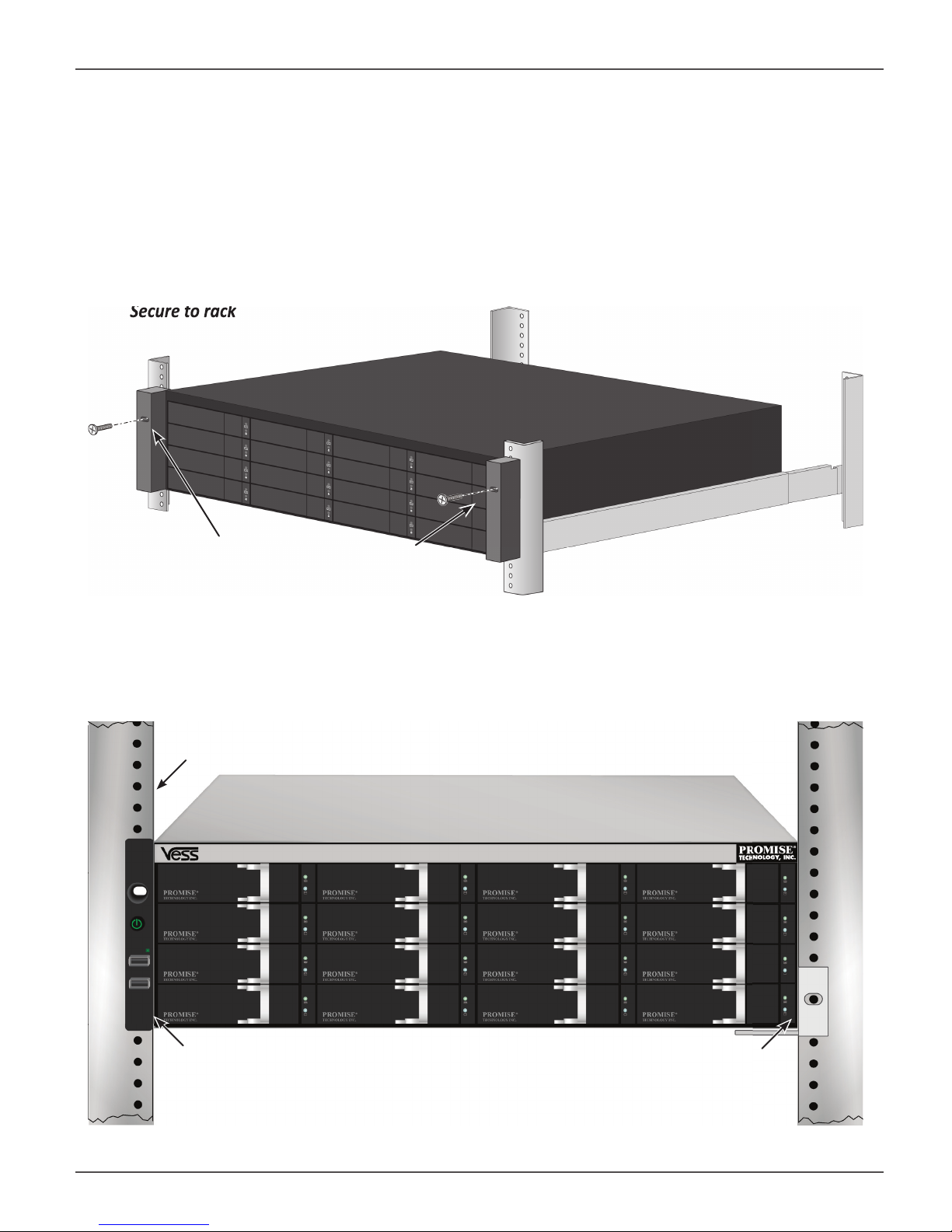
Secure to rack
Vess A2000 Series Product Manual
4. Secure the enclosure to the rack.
• The unit attaches to the rack posts using the included screws and fl ange nuts. One screw each side, in
the upper hole only.
• Use the attaching screws and fl ange nuts that came with the Vess.
Secure to rack
Screws and fl ange nuts attach
the Vess to the rack posts
System installed in rack
Vertical rack post
Handles mount outside the rack post
Mounting rails
mount outside the
rack post
24
 Loading...