

Vespermarine XB-8000, XB-6000 Install Manual
XB-8000 | XB-6000 INSTALL GUIDE
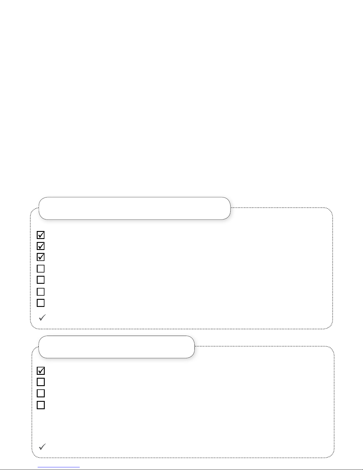
OPTIONAL ACCESSORIES
WHAT YOU NEED TO GET GOING
= Item Included
= Item Included
Congratulations on your purchase. Your XB-8000 / XB-6000
AIS Transponder is a Class B AIS Transponder with integrated
NMEA 2000 and WiFi* connectivity.
The XB provides information to improve your situational awareness and assist in
avoiding collisions at sea. Because it consumes very low power it may be left
turned on whenever your vessel is underway. It works by interpreting Universal
Shipborne Automated Identification System (AIS) messages which are sent over
VHF by transponders installed on other vessels. The AIS system uses two dedicated
VHF channels designated for this purpose and with the installation of the XB to
receive these signals, you can distribute this information to other devices on board
your vessel (e.g. chart plotters, laptops, smart phones) using NMEA 2000, USB and
WiFi*. In addition, your vessel data is transmitted to other AIS-equipped vessels
within range.
For more information on AIS go to www.vespermarine.com/xb.
(*XB-8000 only)
XB-8000 or XB-6000
External GPS Antenna with 10m cable
10 pin power/data cable
AIS/VHF antenna
MMSI number
PC/Mobile Device for configuring XB settings
2A fuse or circuit breaker
1m USB cable (for configuration)
Waterproof 5m USB cable with locking security ring
NMEA 2000 cable, T connector and network extension cable
SP160 Antenna Splitter
Consider other equipment you may need to install this on your vessel e.g.
additional cable, cable ties, mounting screws, wire strippers, screw driver etc.
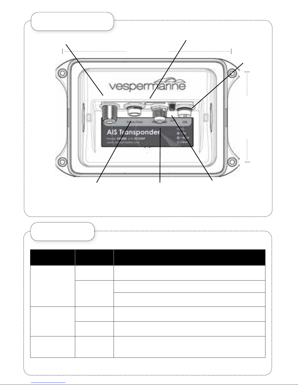
CONNECTIONS
STATUS LED
COLOR STATE DESCRIPTION
Green (OK) Solid Normal Operation
Flashing
Antenna VSWR is high
Background noise level on AIS receiver is high
Orange
(No Transmit)
Solid Device initializing, silent mode, waiting to transmit
Flashing Acquiring a GPS fix
Red (Error) Solid/
Flashing
Built in integrity test error
(See troubleshooting section for more info)
• AIS/VHF antenna
• NMEA 2000
• GPS antenna
• 10 pin power/data port
• LED Status
185mm (7 1/4”)
98mm (3 7/8”)
• USB
Mount your XB at least 0.6m (2 feet) from any compass. Test your compass
to verify that it operates properly when the XB is operating.
VHF ANTENNA
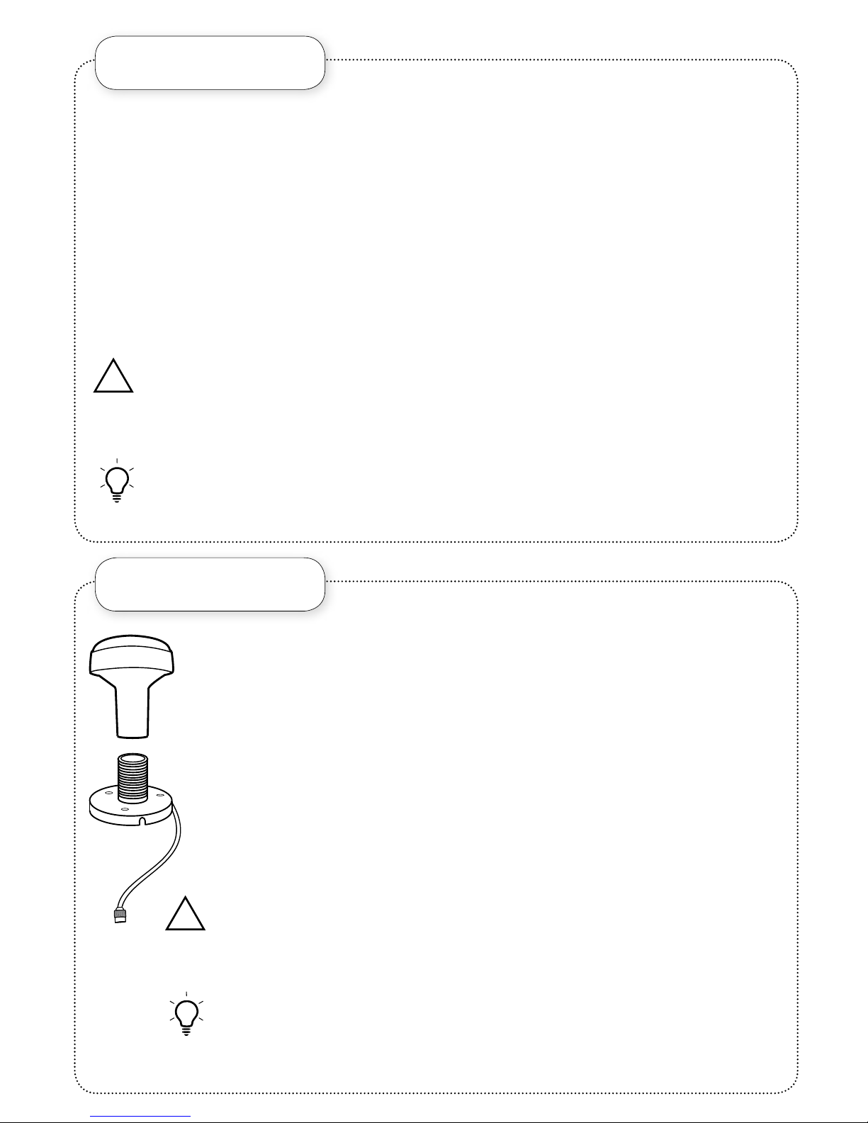
GPS ANTENNA
!
• A dedicated VHF antenna or Vesper Marine AIS/VHF Antenna Splitter
is required.
• Make sure your VHF antenna is an omni-directional antenna designed for the
marine band (156-162MHz) and is well tuned at the AIS end of the band (VSWR
2:1 or less at 162MHz).
• Mount the antenna as high as possible (at least 2-3 metres (6-10 ft) above
the water surface) and as far as practical from any existing VHF, HF or radar
antennas and any metal structures. It is not recommended to place the VHF
antenna directly alongside a mast or another VHF antenna such as on
a mast-head.
CAUTION: Never operate this device unless it is connected to a suitable VHF
antenna or Vesper Marine AIS/VHF Antenna Splitter. Performance cannot be
assured if you use any other antenna splitter. The use of an improper splitter
may damage the device and void your warranty.
HINT: Use the VSWR meter in the vmAIS or WatchMate App
(see configuration section) to check your antenna system installation.
• The XB requires a GPS fix before it can transmit its position.
• The GPS antenna should be situated so that it has an unobstructed
view of the sky above.
• Do not place the GPS antenna near or in the path of radar or
HF antennas.
• The antenna cable is terminated with a small SMA connector to
facilitate easy routing through holes and openings. Do not cut the
cable unless you have the proper tools to crimp a new connector.
Make the connection to your AIS transponder last after antenna
installation is complete.
CAUTION: The GPS antenna provided is designed specifically for
use with the XB Transponder. Performance cannot be assured
unless you use a Vesper Marine GPS antenna. Use of a different
antenna may damage your XB and void your warranty.
HINT: Use the GPS Status screen in the vmAIS or WatchMate App
(see configuration section) to view satellite signal strengths which
will assist in determining the best location for the antenna.
!
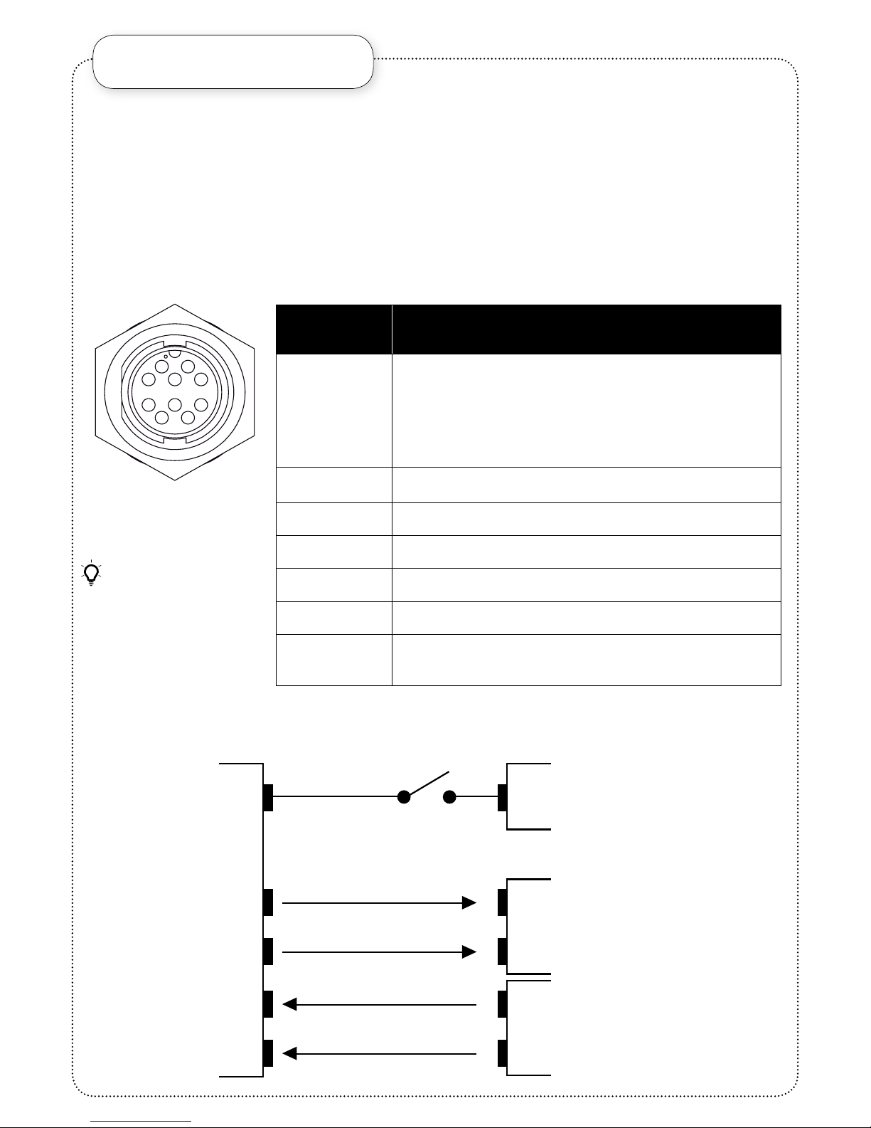
POWER AND DATA
COLOR DESCRIPTION
Red DC positive (+) (12-24 volts). Always use a 2A
fuse or circuit breaker. Do not connect directly
to battery. If you must extend the power
connections use high quality pre-tinned marine
grade wire which is at least 16 AWG (1.5mm2).
Black DC negative (-)
Gray NMEA data out (+) A
Yellow NMEA data out (-) B
Green NMEA data in (+) A
White NMEA data in (-) B
Brown External silent mode switch. Do not connect if
not used.
(Do not connect blue or pink wire)
DATA OUT (+) A
XB CHART PLOTTER
DATA OUT (-) B
DATA IN (+) A
DATA IN (-) B
HEADING SENSOR
DATA OUT (+) A
DATA OUT (-) B
DATA IN (+) A
DATA IN (-) B
(Gray)
(Yellow)
(Green)
(White)
38400 Baud
4800 Baud
DC NEGATIVE / GROUND
(Brown)
EXTERNAL
SWITCH OUTPUT
SILENT MODE SWITCH
NMEA 0183 EXAMPLE
A 2m (6.5’) cable with attached 10 pin connector is supplied for connecting the
XB to power, other devices over NMEA 0183 and an external silent mode switch.
You may extend this cable as necessary.
• Check you have the VHF antenna connected before connecting to power.
• Fully engage the locking ring to ensure a watertight seal.
• Received NMEA 0183 data is output on WIFI* and USB.
Hint: Silent Mode
can also be controlled
over USB and WiFi*.
External switch is
an optional manual
override.
 Loading...