


INSTALLATION GUIDE
M1 HUB - USA & CANADA
M1 HUB - REST OF WORLD
1

Index
Introduction 3
Items you need for installation 4
The Cortex network 5
LED indicator panel 6
M1 port locations 6
M1 positioning 7
M1 mounting 7
Connecting devices to an M1 8
Device connection FAQs 9
To connect power 10
Wiring color codes 10
AIS / VHF Antenna (required) 11
Internal AIS / VHF splitter 11
External GPS Antenna (required) 12
External WiFi Antenna (recommended) 13
To connect to NMEA 2000 14
To connect to NMEA 0183 15
External Cellular Antenna (optional) 16
External Speaker (optional) 17
Connecting devices to an M1 18
To connect a mobile device 18
To connect a handset 19
Device connection FAQs 19
MMSI programming introduction 20
To program an MMSI with the Onboard App 20
To program an MMSI with a handset 21
To confirm AIS operation 21
Monitoring and control 22
Cortex Monitor App introduction 22
To program GPIO sensors with the Cortex
Onboard App 23
To program GPIO sensors with a handset 23
Heading Sensor introduction 24
To update M1 firmware 24
M1 Wiring color codes 25
NMEA PGNs and Monitoring Instruments 26
GPIO sensor wiring - Lighting remote control 27
GPIO sensor wiring - Motion sensor 28
GPIO sensor wiring - High water sensor 29
GPIO sensor wiring - Bilge pump activation sensor 30
GPIO sensor wiring - Hatch / door open sensor 31
GPIO sensor wiring - Smoke / heat sensor 31
Specifications 33
Dimensions - M1, H1, H1P 34
Dimensions - External GPS Antenna 35
Dimensions - External Cellular Antenna 35
LED icon troubleshooting 36
Warnings 38
Warranty 39
2

Introduction
The Vesper Marine Cortex M1 hub is an AIS Class-B SO-TDMA
transponder with integrated on board and remote vessel
monitoring and control.
When paired with a Vesper Marine Cortex H1 or H1P handset, the
M1 hub becomes a fully-featured 25W VHF radio with complete
Class D DSC functionality.
The M1 hub features integrated WiFi providing configuration and
control via a Cortex app or handset.
The M1 hub uses two dedicated AIS channels to transmit and
receive vessel position and other data to and from all other AIS
equipped vessels within range.
The M1 hub uses received AIS data by sharing it with other
devices on board your vessel (e.g. chart plotters, laptops, phones)
over NMEA 2000, NMEA 0183 and WiFi.
For flexibility, the M1 hub includes an integrated AIS/VHF splitter
which allows an existing or secondary VHF radio to share the VHF
Antenna with the M1 hub (the M1 uses a single antenna for VHF
and AIS).
The M1 hub also features an integrated GNSS receiver
(supporting GPS, GLONASS, BeiDou, Galilleo), fully isolated
NMEA ports and a high-power external speaker driver. Internal
antennas for cellular and WiFi are included with the option to
attach external antennas as required.
Off-boat vessel monitoring and control is supported via a built-in
cellular modem and the Cortex Monitor App on your phone.
Integrated sensors provide vessel position, battery voltage,
heading and barometric pressure, while NMEA 2000 or NMEA
0183 provides information from sensors connected to the NMEA
network.
Optional external sensors can be installed and connected to the
M1 hub to monitor information such as bilge level, shore power
and vessel security. Optional output relays can be installed to
remotely control lighting, air conditioning, refrigeration, bilge
pump, battery charging and more.
Questions and FAQs
Visit www.vespermarine.com/faqs for answers to frequently
asked questions, technical support, downloads, local dealer
contacts and more…
Register Your Cortex
Vesper Marine releases product updates from time to time.
These updates often add new features.
To be notified when an update is available please register your
Cortex at www.vespermarine.com/register.
3
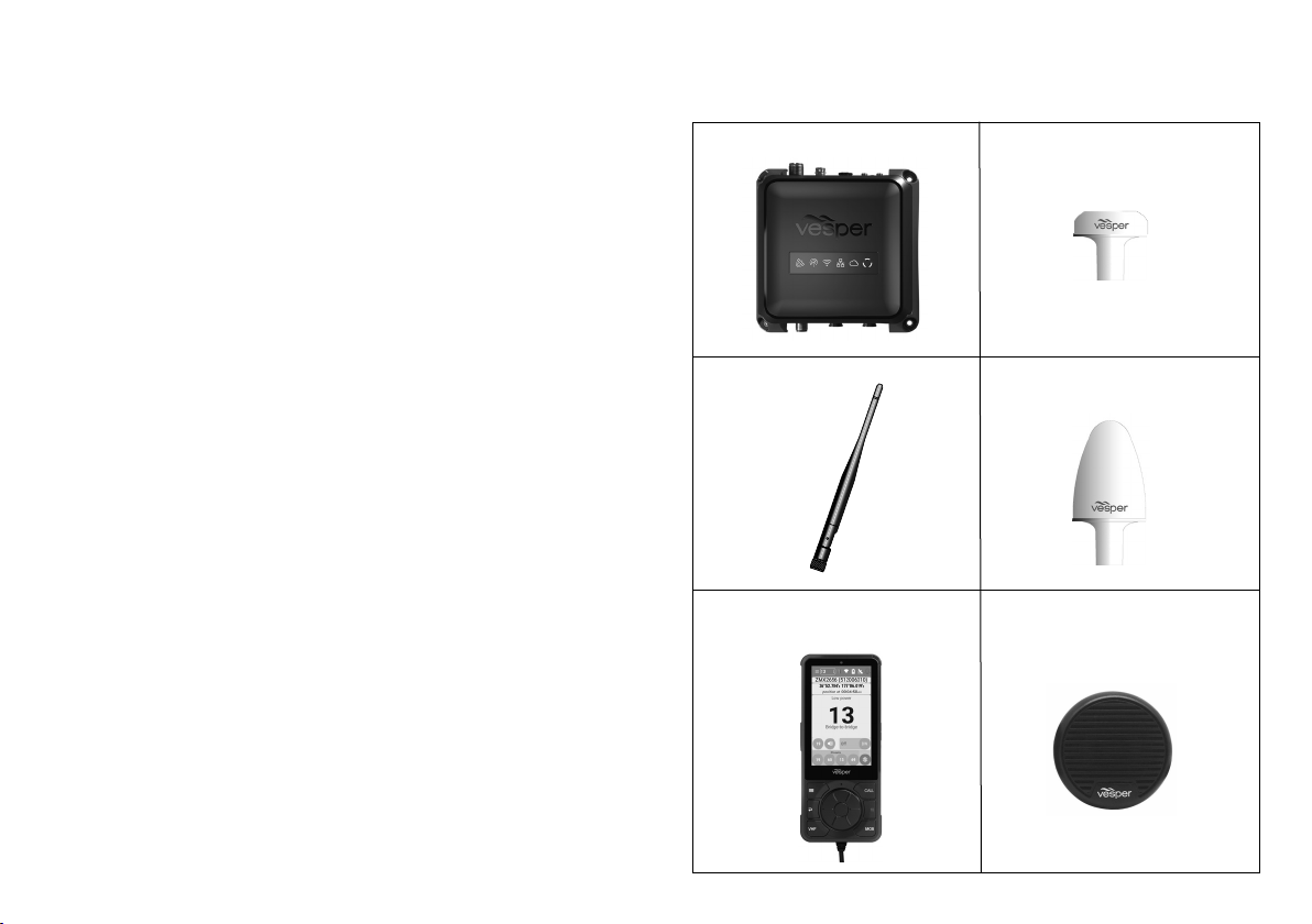
Items you need for installation and configuring
Required components (included)
M1 hub
GPS Antenna
Power cable
WiFi antenna
Audio cable
Input / Output cable
Required components (not included)
AIS/VHF antenna
Fuse or circuit breaker
Fastenings of your choice
Mobile device running the Cortex Onboard App or a Cortex
H1 or H1P handset for configuring.
Optional accessories
Cortex H1 or H1P handset(s)
External speaker
External cellular antenna
NMEA 2000 cable
NMEA 2000 T connector
NMEA 2000 network extension cable
External sensors for Monitoring and Control
M1 hub GPS antenna (included)
External WiFi
antenna
(included)
Cortex H1 or H1P handset
(optional)
External cellular antenna
(optional)
External speaker (optional)
4
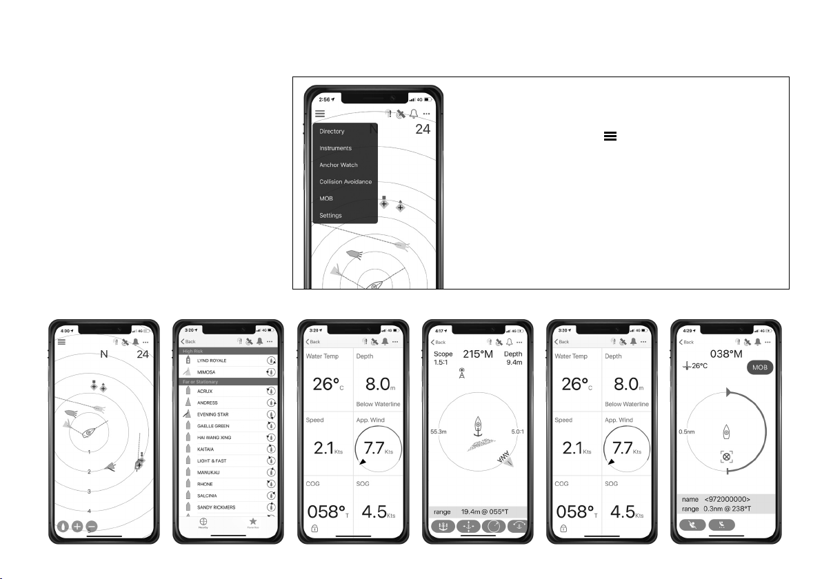
Onboard App Introduction
Cortex Onboard is a free Android and Apple
iOS app that connects your phone or tablet
to the WiFi of the M1.
Use the Cortex Onboard App to configure,
manage and display M1 data. The
Configuration Menu is used for initial
configuration, AIS programming, network
settings, firmware updates and input /
output sensor setup.
Once the M1 is configured, the Cortex
Onboard App provides access to all M1
status and smartAIS display screens in a
similar layout to a Cortex handset.
See To update M1 firmware (pg24).
Cortex Onboard App Main Menu options
Select the Main Menu icon (
Plotter Plotter view of AIS targets
Directory AIS targets and manual DSC contacts
Instruments GPS, integrated sensors and NMEA data
Anchor watch Monitor the vessel at anchor
Collision avoidance Manage a potential collision scenario
MOB Man Overboard monitoring
Settings Configure and manage the M1
Collision avoidanceAnchor watchInstruments MOBDirectoryPlotter
)
5
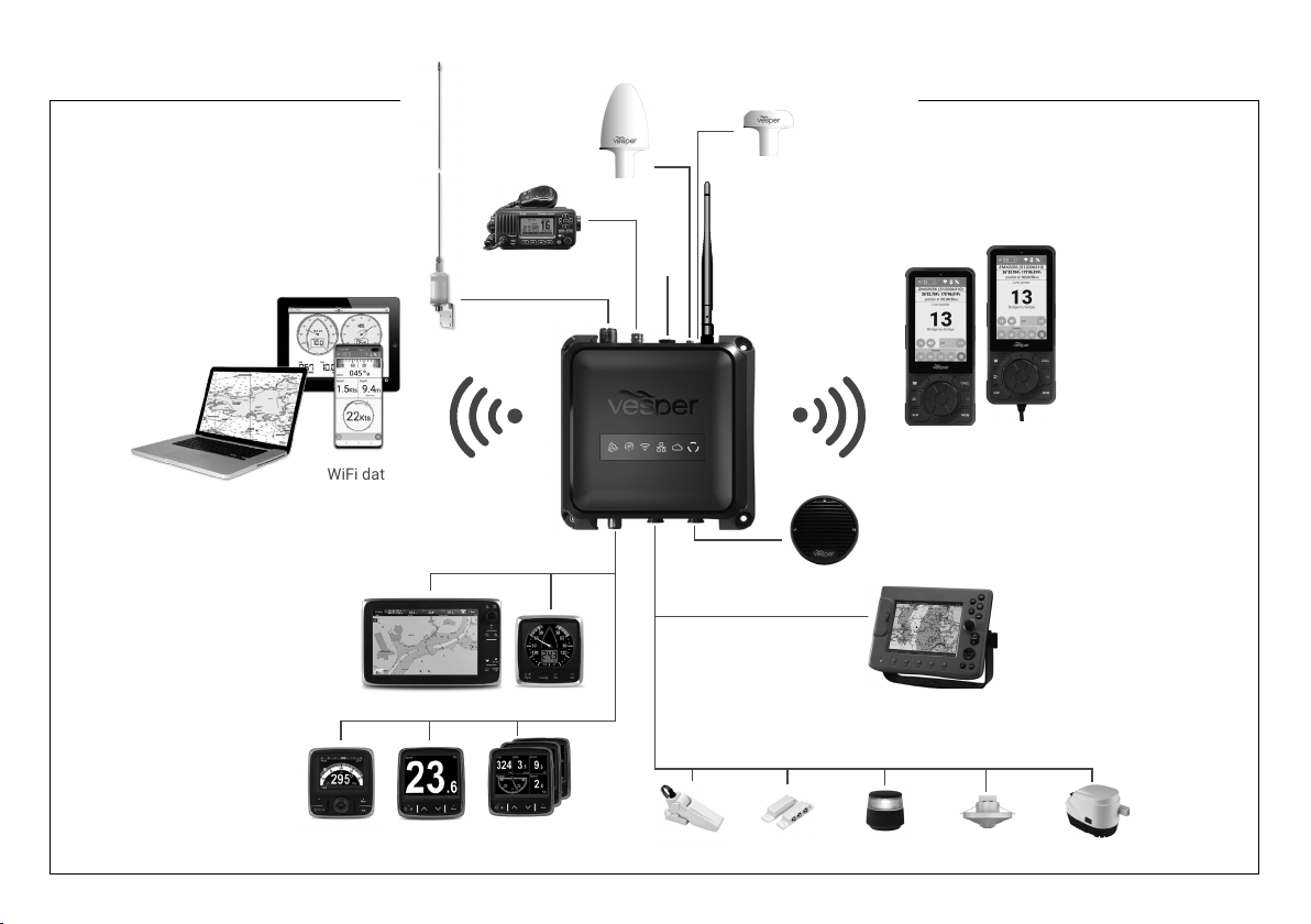
The Cortex network
AIS / VHF
Antenna
Cellular
Antenna
GPS (10 Hz)
Antenna
(included)
WiFi data
Secondary VHF
NMEA 2000
MFD
DepthHeading Others
Wind
Power
12/24V
WiFi Antenna
(included)
Cortex
Handsets
External
Speaker
NMEA 0183
Chart plotter
Remote monitoring Input and Output examples
High water Hatch sensor Lighting Motion sensor Bilge pump
6
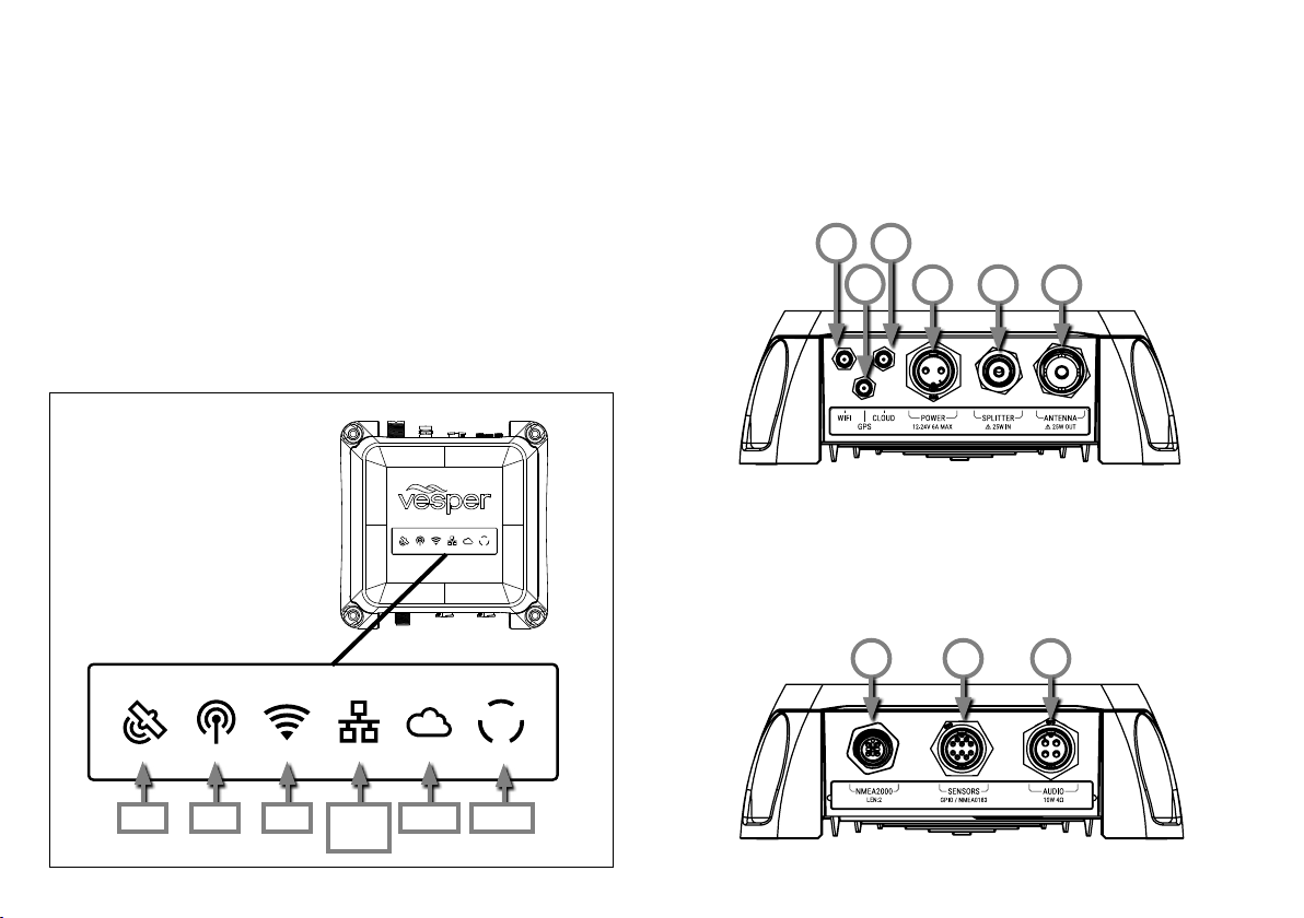
LED indicator panel
M1 port locations
The M1 indicator panel provides system status via orange, green
and red illumination in various stages of solid or flashing.
eg. The GPS icon flashes green momentarily when a fix is
acquired and returns to solid green after a few seconds.
The VHF icon indicates VHF, AIS and DSC as these functions are
all connected to the same AIS/VHF antenna.
Power ON is indicated with white light.
See M1 LED icon troubleshooting (pg36).
1 WiFi Antenna port
2 GPS Antenna port
3 Cellular Antenna port
1 3
2
7 NMEA 2000 port
8 Input / Output port
(NMEA 0183 and GPIO
sensors)
4 5 6
4 DC Power Supply
(12V or 24V DC)
5 Auxiliary VHF port
6 VHF Antenna
9 Audio port
(External Speaker)
987
GPS VHF WiFi NMEA
2000
PowerCloud
7
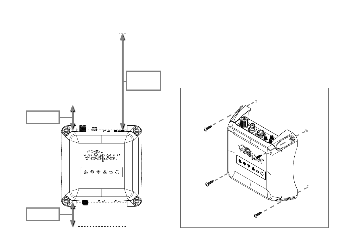
M1 positioning
M1 mounting
Allow at least 2"/ 50mm at each connector
row to give sufficient room for cable
clearance and connection.
Allow at least 8" / 200mm for the external
WiFi antenna to be positioned in a vertical
position to increase WiFi range.
For optimal Heading Sensor performance,
do not mount on or near ferrous materials.
See Heading Sensor introduction (pg24)
CAUTION - Ensure that the minimum safe
compass distance is maintained.
Standard: 0.8 m, Steering: 0.4 m.
Cables Allow
2"/50mm
WiFi Antenna
Allow
8"/200mm
1. Use the M1 as a template for mounting holes.
2. Mark the holes on the mounting surface and drill them
3. Align the M1 to the mounting holes and secure with
fastenings of your choice. (not included)
Recommended scre ws: 316 Stainless Self Tapping
8G/1" (4.2/25.4mm) or 10G/1" (4.8/25.4mm) Pan/Round Head.
Cables Allow
2"/50mm
8
To connect power
M1 DC power requirements:
Nominal 0.5A @ 12V
VHF High Power Transmit (Max) 6.0A @ 12V
Note - Each handset requires 12W of power (1A@12V)
HINT - To provide sufficient power, consider the total system
requirements in terms of adequate cable gauge and fuse rating
with capacity for future expansion (ie, adding an H1 or H1P
handset to the same circuit).
The 2M (6.5ft) power cable (supplied) is terminated with a 2 pin
socket. This cable may be extended or shortened as necessary.
> Check that the VHF antenna is connected before
connecting to live DC power.
> Connect the positive (+ve red) and negative (-ve
black) leads of the power cable to the vessel.
> Connect a fuse or circuit breaker to the positive cable
of the appropriate rating for the system. (ie 10A for the M1,
2A for each handset)
> Connect the power cable to the M1. Tighten the power
cable lock ring clockwise to ensure a secure connection
and watertight seal.
> Turn the vessel's batteries (and/or switch or circuit breaker)
on to apply power to the M1.
> Confirm the M1 is powered on with a visual check on the
M1 indicator lights.
HINT - Connect the M1 to a power supply that will remain on even
when the vessel’s batteries may be turned off. (eg, connected to
the 24hr circuit)
This is important for monitoring to ensure the M1 remains on even
when the main DC power of the vessel is switched off.
M1 wiring diagram
Black
Red
FUSE
Negative -ve
Power +ve
Wiring color codes
Red DC positive (+ve) (12/24 volts).
Black DC negative (-ve)
Always use a fuse or circuit breaker installed near the battery
end or bus bar end.
Do not connect directly to a battery.
If you must extend the power connections use quality tinned
marine grade wire at least 16 AWG (1.5mm²).
9

AIS / VHF Antenna (required)
Internal AIS / VHF splitter
The M1 shares one antenna for both AIS and VHF functions.
A dedicated VHF antenna is required.
Choose a high quality omni-directional VHF antenna designed for
the marine band (156-162MHz) and ensure it is well tuned at the
AIS end of the band (VSWR 2:1 or less at 162MHz).
See Part Number VA159 (AIS/VHF Antenna).
Mount the antenna vertically, as high as possible (at least 2-3
meters (6-10 ft) above the waterline). It is not recommended to
place the VHF antenna near a mast or other metal structures
CAUTION - Install the antenna a minimum of 3m (10ft) from any
other VHF or HF antennas and not within the beam path of a
radar. Inadequate separation may damage the Cortex transponder
and void your warranty.
CAUTION - Never operate the M1 unless it is connected directly
to a suitable VHF antenna.
HINT - The VHF indicator light will display red when a problem
is detected with the antenna system (ie, the VSWR is above the
acceptable level).
What does VSWR mean ?
VSWR stands for Voltage Standing Wave Ratio and is a measure
of the how well matched a transmission line (e.g. the antenna
cable connected to the VHF output of your the M1) is to its
termination impedance (e.g. your antenna).
VSWR can be thought of as a comparative measure of how much
power, generated from your M1 AIS transponder, is delivered to
the antenna and how much of it is reflected back and lost in the
poorly matched transmission line.
A high VSWR will reduce your effective transmission range and
may also lead to other problems.
10
The M1 incorporates an AIS/VHF splitter to share one AIS/VHF
antenna and to allow connection to an external VHF radio via the
auxiliary port.
The auxiliary port protects the transponder while an external VHF
is transmitting (up to 25W) and also isolates the external VHF
radio when the M1 is transmitting.
The auxiliary port will still provide a path to the antenna for the
external VHF radio in the event of an M1 power failure.
AIS / VHF Antenna connection
Auxiliary VHF
VHF Antenna
> Connect the AIS/VHF Antenna plug (PL259) to the M1 port
labeled ANTENNA.
> Tighten clockwise.
> (If applicable) Connect the auxiliary VHF antenna cable
(BNC) to the auxiliary VHF port labeled SPLITTER.
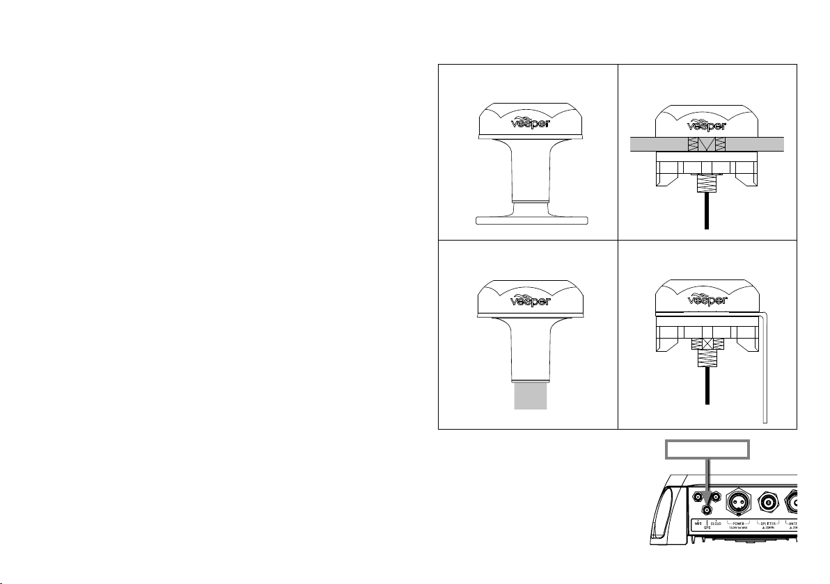
External GPS Antenna (required)
External GPS Antenna mounting
Consider the following location and connection requirements:
- The GPS antenna should be positioned with an unobstructed
view of the sky.
- The GPS antenna is rated IP67 and UV stable for external
installation.
- Do not place the GPS antenna near or in the path of radar, HF
and/or high power satellite communication (such as Iridium Go)
antennas.
- You cannot use another GPS or any other NMEA device
to provide a GPS position to the M1. Class B AIS SO-TDMA
transponders are required by international regulations to use
their own GPS.
- You may use the M1 to share GPS position data to other
devices over NMEA 2000, 0183 or WiFi.
- The antenna cable is terminated with an SMA connector to
facilitate easy routing through holes and openings. Do not cut
the cable without the correct tools to crimp on a new connector.
HINT - Use the GPS Status screen in the Onboard App or handset
to view the satellite signal strengths and determine the best
location for mounting the external GPS antenna.
CAUTION - The Vesper Marine GPS antenna is specifically
designed for use with Vesper Marine devices. Use of a different
GPS antenna may damage the M1 hub and void the warranty.
Deck mount on base
Pole mount
1” 14 UNS threaded mast
> After installing the GPS Antenna,
connect the SMA connector of
the GPS Antenna cable to the
M1 port labeled GPS.
> Tighten clockwise.
Do not over torque.
Deck mount flush
Vertical surface mount
GPS Antenna
11

External WiFi Antenna (recommended)
Consider these WiFi requirements when choosing a position:
- Allow enough clearance space when installing the M1 for the
External WiFi Antenna to be positioned in a vertical position to
increase WiFi range.
- Do not place the External WiFi Antenna near or in the path
of radar, HF and/or high power satellite communication (such as
Iridium Go) antennas.
- Consider the distance between the handset and M1 onboard.
Some objects and materials such as steel, aluminum and carbon
composites may provide interference to degrade the WiFi signal
strength.
External Wifi Antenna Configuration
Cortex Onboard App:
> Menu (
> Device Settings > Networks > WiFi...
> Use external antenna (select on/off)
Cortex handset:
> Main Menu (
the Configuration Menu.
> Networks > WiFi...
> External Antenna (select on/off)
WiFi signal strength is checked via the WiFi icon on the handset
status bar or the WiFi signal on your device.
) > Settings
). Touch on the wrench icon ( ) to open
External WiFi Antenna installation
WiFi Antenna
> Connect the WiFi Antenna to the M1
port labeled WiFi.
> Tighten clockwise. Do not over torque.
> Adjust the angle of the WiFi antenna to
be as close to vertical as practical.
HINT - Install the WiFi Antenna last to allow
sufficient room for fingers to first access and
install the other SMA size connectors attached
to the External GPS and optional cellular
antenna for cloud connectivity.
HINT - Installations where an M1
is mounted in close proximity
to an H1 (with little or no
interference to the WiFi
signal) may not require
fitment of the External
WiFi Antenna.
Note - The M1 includes an internal WiFi antenna for installations
where the external antenna is not required.
12

NMEA 2000 Gateway
The M1 incorporates an NMEA Gateway to allow different brands
and generations of electronics on NMEA 0183 or 2000 networks
to talk to each other automatically and transfer data without extra
multiplexing devices or configuring.
The Gateway translates selected NMEA 2000 sensor data for
compatibility with mobile apps. Monitor navigation data on your
Cortex Onboard App on your phone or tablet or use it with third
party apps of your choice.
Data is made available to NMEA 0183 and 2000 plotters. The
Gateway supports a range of wind, depth, speed, heading,
temperature, barometric pressure and autopilot PGNs.
See PGNs sent and received by the gateway (pg26).
Example Case #1:
Sailing and navigation apps cannot talk directly to an NMEA 2000
network as the apps use the 0183 protocol. We need to translate
data from NMEA 2000 to 0183.
Gateway: The M1 receives NMEA 2000 PGNs and automatically
converts these to 0183 sentences and sends to devices running
the sailing and navigation apps via WiFi.
Example Case #2:
A vessel has an older chart plotter (NMEA 0183 only) with new
NMEA 2000 sailing instruments.
Gateway: The M1 receives the new instrument data from the
vessel’s NMEA 2000 network and automatically converts the data
to 0183 sentences for the chart plotter. The chart plotter 0183
wires are connected to the 0183 wires on the M1's input/output
cable.
NMEA 2000 Gateway example
WiFi data
NMEA 2000
MFD
NMEA 0183
Wind
Depth
DepthHeading Wind
Chart plotter
13

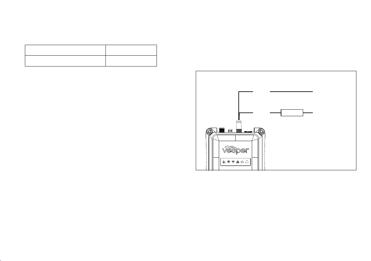
Chart plotter
Terminating
Resistor
T Connection
Network
extension cable
Network
power
Drop cable
To connect to NMEA 2000
The M1 can be connected to an NMEA 2000 network to enable
AIS and Navigation data, including GPS to be sent to other NMEA
2000 devices.
- The NMEA sentences (PGNs) supported are listed on page 26.
- A NMEA 2000 drop cable and T connector are required to
connect the M1 to a vessel’s NMEA 2000 network.
- Modifying the Instance or System Identification can be done via
the Cortex Onboard App or from the H1 handset.
Cortex Onboard App:
> Menu (
) > Settings > Device Settings > Networks
> NMEA 2000...
> Device Instance (0-255) (select to enter value)
> System Instance (0-255) (select to enter value)
Cortex handset:
> Main Menu (
the Configuration Menu.
> Networks
> N2000 (NMEA 2000)
). Touch on the wrench icon ( ) to open
> Device Instance
> System Instance
To change the Device or System instance select the field and use
the touchscreen menu to key a number between 0-255
NMEA 2000 network connection example
NMEA 2000 port
14

SPEAKER +VE
SPEAKER -VE
BLACK
(Shared with GPIO Ground)
To connect to NMEA 0183
NMEA 0183 devices can receive AIS data when connected to the
M1 I/O (Sensors GPIO / NMEA 0183) expansion port.
- The NMEA sentences supported are included on page 26.
The NMEA Baud rate can be changed via the Cortex Onboard App
or from the H1 handset.
Cortex Onboard App:
> Menu (
) > Settings > Device Settings
> Networks > NMEA 0183... > Baud rate (select)
Cortex handset:
> Main Menu (
the Configuration Menu.
). Touch on the wrench icon ( ) to open
> Networks
> 0183 (NMEA 0183)
> Baud In >
> Baud out >
HINT - AIS output requires a minimum of 38400 Baud rate.
Note - When connecting the M1 to NMEA 0183 devices, connect
0183 Common (Black) to the vessel's negative bus.
This is to ensure a satisfactory grounding as the NMEA
0183 network of the M1 is isolated.
NMEA 0183 network connection diagram
NMEA TX (+) A
NMEA TX (-) B
NMEA RX (+) A
NMEA RX (-) B
NMEA 0183 COMMON
ORANGE
WHITE
DARK GREEN
YELLOW
BLACK
NMEA 0183 port
15

External Cellular Antenna (optional)
External Cellular Antenna mounting
The Vesper Marine External Cellular Antenna may be connected
for enhanced cellular coverage. Consider the following location
and connection requirements:
- The external cellular antenna is rated IP67 and UV stable
for external installation.
- Do not place the external cellular antenna near or in the path
of radar, HF and/or high power satellite communication (such
as Iridium Go) antennas.
- The antenna cable is terminated with an SMA connector to
facilitate easy routing through holes and openings. Do not cut
the cable without the correct tools to crimp on a new connector.
- Do not extend the antenna cable beyond the supplied
length of 5M (16').
HINT - A solid orange light on the LED indicator panel indicates
an attempt to connect to a cell tower, green indicates connection.
See LED icon troubleshooting (pg36) for further information.
External Antenna Configuration
Cortex Onboard App:
> Menu (
> Device Settings > Networks > Cloud...
> Use external antenna (select on/off)
Cortex handset:
> Main Menu (
the Configuration Menu.
> Networks > Cloud
> Use external antenna (select on/off)
Note - The M1 includes an internal Cellular antenna for
installations where the external antenna is not required.
16
) > Settings
). Touch the wrench icon ( ) to open
Deck mount
on base
Pole mount
1” 14 UNS
threaded
mast
> After installing the Cellular
Antenna, connect the SMA
connector of the Cellular
Antenna cable to the M1 port
labeled Cloud.
> Tighten clockwise.
Do not over torque.
Deck mount
flush
Vertical
surface
mount
Cellular Antenna

External Speaker (optional)
ORANGE
WHITE
DARK GREEN
YELLOW
ORANGE
BLACK
RED
BROWN
LIGHT GREEN INPUT / OUTPUT 2
BROWN INPUT / OUTPUT 1
GRAY INPUT 3
VIOLET INPUT 2
BLUE INPUT 1
RED
PULLUP VOLTAGE
AUDIO +VE
AUDIO -VE
Reserved - Do not connect
Reserved - Do not connect
BLACKNMEA 0183 COMMON
An optional external speaker can be connected to the M1 for
audio alarms or voice alarms using the Audio cable.
In addition, the speaker also broadcasts VHF voice when the M1
is connected to an H1 or H1P handset.
Make sure that the external speaker is installed at least 3ft / 1M
from any magnetic compass or flux gate sensor.
External Speaker wiring color codes
Orange Audio positive (+ve)
Black Audio negative (-ve)
HINT - For best audio performance, choose a speaker with a
minimum 10W audio power rating and 4 ohm impedance.
Vesper Marine External Speaker
The Vesper Marine External Speaker (Part Number 111210) is
purpose designed for the marine environment.
Featuring IP66 ingress protection this speaker is suitable for
installing almost anywhere on board.
- 3” 70 Watt Speaker
- Frequency response of 80Hz-18kHz
- 4 ohm impedance
- IP66 water resistant for marine applications
- UV resistant polymer housing / Polypropylene cone
- Heavy duty molded ABS plastic basket and grill
- Pre-wired with 2m (6.5ft) of cable
External Speaker Wiring Diagram
Audio positive (+ve)Orange
Black
Audio negative (-ve)
Side Front
93.5mm (3 11/16”)
74.5mm (2 15/16”)
55.6mm (2 3/16”)
External Speaker Dimensions
86mm (3 3/8”)
DRILL / CUT DRILL X 4
ø 74.5mm (2 15/16”)
ø 4mm (5/32”)
86mm (3 3/8”)
93.5mm (3 11/16”)
17

Connecting devices to an M1
To connect a mobile device
Once installation of the M1, cables and antennas are complete,
the M1 is configured using the Cortex On board App on a mobile
device (iOS or Android) or via a Cortex H1 or H1P handset.
Prior to the configuration steps, a WiFi connection must be made
between the M1 and the device used for configuration.
The M1 WiFi network will connect with up to 10 devices.
Note - The Cortex V1 package (M1+H1) ships with the handset
pre-configured to the M1.
Place supplied
WiFi label here
Caution - The WiFi
SSID or password
cannot be changed,
please ensure the
labels do not get lost.
1 Turn Cortex M1 and device ON
Switch the vessel's batteries ON to power the M1.
2 Select WiFi in the settings of the device
> From the list of available WiFi, identify and select
the M1 WiFi SSID.
Note - The WiFi SSID is identified by the
M1 serial number eg: CORTEX-95211616
> Key the WiFi password found on the label
supplied with the M1.
Alternatively scan the QR code of the M1 (found
on the WiFi label) to be automatically connected.
> Join and save to connect.
> Close the WiFi setting on the device.
Note - If the supplied label is lost, the WiFi password is
found underneath the M1 on the serial label.
For further assistance please contact Vesper
Marine via support@vespermarine.com.
18

To connect a handset Device connection FAQs
1 Turn M1 ON
Switch the vessel's batteries ON to power the M1.
2 Turn the handset ON
Press and hold the Power button for 2 seconds.
3 Select WiFi from the Status Bar
WiFi status
> From the list of available WiFi, identify and select
the M1 WiFi SSID.
Note - The WiFi SSID is identified by the
M1 serial number eg: CORTEX-95211616
Note - The Cortex V1 package (M1+H1) ships with
the handset pre-configured to the M1.
> Key the WiFi Password found on the label
supplied with the M1.
> Select CONNECT to save.
Text ‘connected’ will confirm the connection.
> Select the Back key to close the WiFi status
Note - To connect additional handsets to a configured M1 network
follow the To connect a handset steps above.
If the device (handset or mobile device) displays 'Trying to
connect...’ for a long period, it has not made a WiFi connection to
the M1.
> Confirm the M1 is ON
> Check the WiFi signal strength on the mobile device or in
the Status Bar of the handset.
> Check the M1 WiFi External Antenna is attached.
> Consider the distance between the device and M1 on
board. Some objects and materials may provide
interference to degrade the WiFi signal strength.
> See 'Connecting to an M1' (pg18).
Follow the steps to identify and connect to the WiFi.
Note - The WiFi status icon on the M1 will illuminate
green when a handset or app makes a connection.
If the device displays 'No GPS connection!' while beeping an
alarm, touch the screen (or any key) to silence the alarm and
close this notification.
The device will then display 'Waiting for GPS...’ , the M1 has not
acquired GPS position.
> Check GPS Status in the Status Bar of the
handset (select GPS icon in the On board App).
> Check the M1 external GPS installation.
> Check the GPS icon on the M1 indicator panel.
19

MMSI programming Introduction
To program an MMSI with the Onboard App
Before an M1 can transmit your position over AIS you must
configure your vessel details and enter a valid MMSI number.
You can configure your MMSI using the Cortex Onboard App or a
Cortex handset.
Your MMSI may have been entered by your dealer. You must have
an assigned MMSI for your vessel.
If you do not have an assigned MMSI, contact the relevant
authority in your country.
Once you save the MMSI number you cannot change it. If you
need to change the MMSI, please contact an authorized dealer or
Vesper Marine.
MMSI Programming Warning
For Customers in the USA: This device must be programmed with
data corresponding to the vessel on which it will be installed.
Programming must be carried out by a Vesper Marine dealer.
The included instructions contain information on how to verify the
correct programming.
WARNING: It is a violation of the rules of the Federal
Communications Commission to input an MMSI that has not
been properly assigned to the end user, or to otherwise input any
inaccurate data in this device.
20
1 Download the Cortex Onboard App
Free download from the Apple or Google Play stores
2 Turn Cortex M1 and device ON
Switch the vessel's batteries ON to power the M1
2 Connect the device to the M1 via WiFi
See Connecting to an M1 section
4 Open the app and program as follows;
> Select the Main Menu icon (
Menu.
> Device Settings...
> Vessel...
> Identification...
> MMSI (Enter MMSI number)
> Name (Enter the vessel’s name)
> Callsign (Enter the vessel’s callsign)
> ATIS ID* (Enter the vessel's ATIS ID)
*A vessel ID for inland waterways in some European countries.
> Vessel Type (Select from the list)
To program your vessel dimensions with the Onboard App
> Select the Menu icon (
> Device Settings...
> Vessel...
> Dimensions
> Length (Enter length overall)
> Beam (Enter beam overall)
> GPS from stern (Enter measurement)
> GPS from starboard (Enter measurement)
) to open the Settings
) to open the Settings Menu.

To program an MMSI with a handset
To conrm AIS operation
1 Turn Cortex M1 and handset ON
Switch the vessel's batteries ON to power the M1
2 Connect the handset to the M1 via WiFi
See Connecting to an M1 section
3 Select the handset Main Menu and program as follows;
> Main Menu. (
the Configuration Menu.
) Select the wrench icon ( ) to open
> Vessel
> Vessel Identification
> MMSI (Enter MMSI number)
> Name (Enter the vessel’s name)
> Callsign (Enter the vessel’s callsign)
> Vessel Type (Select from the list)
To program your vessel dimensions with a handset
> Main Menu. (
the Configuration Menu.
) Select the wrench icon ( ) to open
> Vessel
> Dimensions
> Length (Enter length overall)
> Beam (Enter beam overall)
> GPS from stern (Enter measurement)
> GPS from starboard (Enter measurement)
LED indicator panel
Green light indicates
VHF
AIS data transmission
Handset
> Main Menu. (
to open the Configuration Menu.
) Select the wrench icon ( )
> Systems
> AIS (View RX and TX data counter)
Onboard App
> Main Menu (
) to open the Settings Menu.
> Device Settings > Systems...
>AIS... (View RX and TX data counter)
Onboard App (or handset Status Bar pictured)
Transponder receive only mode (Stealth mode)
is controlled (on/off) from within this menu.
Transponder status
21

Monitoring and control Cortex Monitor App Introduction
Off-boat vessel monitoring and control is supported via a built-in
cellular modem and the Cortex Monitor App on your phone.
Once the M1 is installed and operating, data from the M1's
integrated sensors, from external sensors wired into the GPIO
port and data from an NMEA bus will be displayed and controlled
on the Cortex Monitor App.
M1 integrated sensors
GPS position
System voltage
Vessel heading (refer Heading Sensor Calibration pg24)
Barometric pressure
M1 GPIO sensors and connections
The M1 can monitor up to three general purpose inputs and an
additional two may be configured either as an input or output.
Note - When connecting GPIO sensors to the M1, a Pullup voltage
connection is recommended.
Pullup voltage provides an active high/low voltage
reference for the GPIO input when sensors do not provide
sufficient voltage.
NMEA 2000 sensors
When the M1 is connected to an NMEA 2000 bus, data from
applicable NMEA 2000 and 0183 devices will display on the
handset and Onboard App Instruments screen, and on the Cortex
Monitor App.
See page 26 for the NMEA PGNs received and transmitted and
Monitoring Instruments received.
Cortex Monitor is a free Apple iOS and Android app that allows
your phone to monitor and control the sensors of your Cortex M1
via a cellular connection.
Use the Cortex Monitor App to monitor and control your boat when
you are ashore provided your Cortex M1 and phone are within
cellular coverage.
Note - Use the Cortex Onboard App or a handset to configure and
test GPIO sensors and relays.
After the inputs and outputs have been configured and tested,
download the Cortex Monitor App onto your device.
Enter your login details and the Cortex Product Serial number or
scan the QR code to activate monitoring for your Cortex M1. Once
activated it can take a few minutes for your Cortex M1 to connect
for the first time. You can now view the status of M1 sensors on
the Monitor app.
PowerInstrumentsTracking
22

Onboard App
Name and configure up to 5 general purpose sensors,
2 x input/output, 3 x input.
To program GPIO sensors with a handsetTo program GPIO sensors with the Cortex
Name and configure up to 5 general purpose sensors,
3 x input, 2 x input/output.
1 Download the Cortex Onboard App
Free download from the iOS or Google Play stores
2 Turn Cortex M1 and device ON
Switch the vessels batteries ON to power the M1
2 Connect the device to the M1 via WiFi
See Connecting to an M1 section
4 Open the app and program as follows;
> Select the Main Menu icon (
Menu.
> Device Settings...
> Sensors...
> GPIO...
> Sensor / control name
> Sensor / control type (select from list)
> Default input high
> Pullup active (select Enabled or Disabled)
> Active when high (select Yes for Normally Closed
select No for Normally Open)
Note - An external Pullup voltage connection is recommended when connecting GPIO sensors to the M1.
When a sensor does not provide more than 2V, the Pullup provides an appropriate high level reference for the M1's input.
) to open the Settings
1 Turn Cortex M1 and handset ON
Switch the vessels batteries ON to power the M1
2 Connect the handset to the M1 via WiFi
See Connecting to an M1 section
3 Select the handset Main Menu and program as follows;
> Main Menu. (
the Configuration Menu.
> Sensors
> GPIO
> Sensor / control name
> Sensor / control type (select from list)
> Default input high
> Pullup active (select Enabled or Disabled)
> Active when high (select Yes for Normally Closed
select No for Normally Open)
) Select the wrench icon ( ) to open
23

Heading Sensor introduction
To update M1 rmware
The M1 includes an internal heading sensor to display an
accurately orientated AIS icon of your vessel on another vessels
AIS system. The heading sensor also determines the direction to
the bow for Anchor Watch.
Note - If an external heading sensor exists on the NMEA 0183 or
2000 network, M1 heading sensor calibration is not required. The
M1 will automatically receive the heading PGN from the networked
device.
The Cortex Onboard App
1 Turn Cortex M1 and device ON
Switch the vessel's batteries ON to power the M1
2 Connect the device to the M1 via WiFi
See Connecting to an M1 section
3 Open the app and program as follows;
> Select the Main Menu icon (
Menu.
> Device Settings...
> Sensors...
> Heading...
With a handset
1 Turn Cortex M1 and handset ON
Switch the vessel's batteries ON to power the M1
2 Connect the handset to the M1 via WiFi
See Connecting to an M1 section
3 Select the handset Main Menu and program as follows;
> Main Menu. (
the Configuration Menu.
> Sensors
> Heading
24
) Select the wrench icon ( ) to open
) to open the Settings
Firmware updates for the M1 hub and H1/H1P handsets are
bundled with Cortex Onboard App releases.
Check the Apple IOS App Store or Google Play Store for updates
to Cortex Onboard, select UPDATE as required.
Once downloaded to your mobile device, connect it to the M1 WiFi
on the vessel.
The M1 will automatically recognize updated firmware.
The Onboard App will ask if you would like to perform the firmware
update. Select Yes to update.
Note - If you have registered your Cortex, emails will advise when
a firmware update is available.

M1 Wiring color codes
NMEA TX (+) A
NMEA TX (-) B
NMEA RX (+) A
NMEA RX (-) B
NMEA 0183 COMMON
and GPIO GROUND
ORANGE
WHITE
DARK GREEN
YELLOW
BLACK
RED
BLACK
ORANGE
BLACK
RED
BROWN
RED
LIGHT GREEN INPUT / OUTPUT 2
BROWN INPUT / OUTPUT 1
GRAY INPUT 3
VIOLET INPUT 2
BLUE
POWER +VE
POWER -VE
AUDIO +VE
AUDIO -VE
Reserved - Do not connect
Reserved - Do not connect
PULLUP VOLTAGE
INPUT 1
25

NMEA PGNs and Monitoring Instruments
Received PGNs
PGN Description 0183 Translation
127250 Vessel Heading HDG
128259 Speed, water referenced VHW
128267 Water depth DPT
128275 Distance log V LW
129283 Cross track error XTE
129284 Navigation data BOD APB RMB
129285 Navigation, route/waypoint info WPL RMB
129810 Wind data MDW MWV
129284 Actual Pressure XDR MDA
130314 Air Pressure MTW
Received PGNs are translated and outputted over NMEA 0183
and WiFi. See www.vespermarine.com for an up to date list.
Sent PGNs
PGN Description
127233 Man Overboard
127250 Vessel Heading
127267 Water depth
129025 Position (Rapid)
129026 COG & SOG (Rapid)
129029 GNSS Position
129038 Class A Position
129039 AIS Class B position
129040 AIS Class B position extended
129041 AIS Aids to Navigation
129539 GNSS DOP’s
129540 GNSS satellites in view
129794 AIS Class A Static Voyage
129798 AIS SAR Aircraft Position
129801 AIS Addressed Safety
129802 AIS Safety Related Broadcast
129809 AIS Class B “CS” Static, Part A
129810 AIS Class B “CS” Static, Part B
130306 Wind data
26
Monitoring Instruments
Description
Vessel Heading
Speed, water referenced
Water depth
Wind data
Actual Pressure
Air Pressure

GPIO sensor wiring - Lighting remote control
GPIO sensor configuration example
Sensor / control name Anchor light
Sensor / control type On/Off switch
RED
LIGHT
LIGHT
GREEN
GREEN
INPUT/OUTPUT 2
Note - Lighting on/off remote control is one example of what an
output relay may switch and control.
PULLUP
VOLTAGE
+ve 12/24V
Output relay
C
C
+ve -ve
Light
NO
BROWN
BROWN
GRAY
GRAY
VIOLET
VIOLET
BLUE
BLUE
BLACK
INPUT/OUTPUT 1
INPUT 3
INPUT 3
INPUT 2
INPUT 2
INPUT 1
INPUT 1
GPIO GND
-ve
Note - An external Pullup voltage connection is recommended when connecting GPIO sensors to the M1.
When a sensor does not provide more than 2V, the Pullup provides an appropriate high level reference for the M1's input.
27

-ve
VIOLET
BLUE
BLACK
INPUT 2
INPUT 1
GPIO GND
Bilge pump
GPIO sensor wiring - Motion sensor
GPIO sensor configuration example
Sensor / control name Cockpit Motion 1
Sensor / control type Security sensor
Default input high Pullup enabled
Active when high Yes, normally closed
RED
LIGHT
GREEN
BROWN
GRAY
VIOLET
BLUE
PULLUP
VOLTAGE
INPUT/OUTPUT 2
INPUT/OUTPUT 1
INPUT 3
INPUT 2
INPUT 1
+ve 12/24V
V + V -
NC
C
BLACK
GPIO GND
-ve
Note - An external Pullup voltage connection is recommended when connecting GPIO sensors to the M1.
When a sensor does not provide more than 2V, the Pullup provides an appropriate high level reference for the M1's input.
28

add pullup to system voltage
NO
GREEN
BROWN
VIOLET
BLACK
GPIO sensor wiring - High water sensor
GPIO sensor configuration example
Sensor / control name Bilge high water
Sensor / control type High water sensor
Default input high Pullup enabled
Active when high No, normally open
+ve 12/24V
RED
LIGHT
GREEN
BROWN
GRAY
VIOLET
BLUE
BLACK
PULLUP
VOLTAGE
INPUT/OUTPUT 2
INPUT/OUTPUT 1
INPUT 3
INPUT 2
INPUT 1
GPIO GND
-ve-ve
Note - An external Pullup voltage connection is recommended when connecting GPIO sensors to the M1.
When a sensor does not provide more than 2V, the Pullup provides an appropriate high level reference for the M1's input.
29

BILGE PUMP
GPIO sensor wiring - Bilge pump activation sensor
GPIO sensor configuration example
Sensor / control name Engine room bilge
Sensor / control type Bilge pump
Default input high Pullup disabled
Active when high Yes, normally closed
RED
(not requied in this example)
Three way switch
manual on / off / auto on
PULLUP VOLTAGE
+ve 12/24V
Float switch
LIGHT
GREEN
BROWN
GRAY
VIOLET
BLUE
BLACK
INPUT/OUTPUT 2
INPUT/OUTPUT 1
INPUT 3
INPUT 2
INPUT 1
GPIO GND
+
Bilge pump
Warning light
or alarm
-ve
Note - A Pullup connection is not required in this example as it is driven high.
30

add system voltage and
connect pullp
LIGHT
GREEN
BROWN
GRAY
VIOLET
BLUE
BLACK
RED
GPIO sensor wiring - Hatch / door open sensor
GPIO sensor configuration example
Sensor / control name Forward Hatch 1
Sensor / control type Security sensor
Default input high Pullup enabled
Active when high No, normally open
+ve 12/24V
RED
LIGHT
GREEN
BROWN
GRAY
VIOLET
BLUE
BLACK
PULLUP
VOLTAGE
INPUT/OUTPUT 2
INPUT/OUTPUT 1
INPUT 3
INPUT 2
INPUT 1
GPIO GND
Magnetic reed switch
-ve
Note - An external Pullup voltage connection is recommended when connecting GPIO sensors to the M1.
When a sensor does not provide more than 2V, the Pullup provides an appropriate high level reference for the M1's input.
31

-ve
SMOKE / HEAT DETECTOR
BLUE
BLACK
INPUT 1
GPIO GND
BLUE
BLACK
LIGHT
GREEN
BROWN
GRAY
VIOLET
BLUE
BLACK
RED
GPIO sensor wiring - Smoke / Heat sensor
GPIO sensor configuration example
Sensor / control name Engine room smoke
Sensor / control type Smoke sensor
Default input high Pullup enabled
Active when high No, normally open
RED
LIGHT
GREEN
BROWN
GRAY
VIOLET
BLUE
PULLUP
VOLTAGE
INPUT/OUTPUT 2
INPUT/OUTPUT 1
INPUT 3
INPUT 2
INPUT 1
+ve 12/24V
V + V -
NO
C
BLACK
GPIO GND
-ve
Note - An external Pullup voltage connection is recommended when connecting GPIO sensors to the M1.
When a sensor does not provide more than 2V, the Pullup provides an appropriate high level reference for the M1's input.
32

Specifications
M1 GENERAL
HUB SIZE
POWER SUPPLY
WEIGHT 770g (1.7lb)
ENVIRONMENTAL Waterproof (IPx7)
OPERATING
TEMPERATURE
SUPPORTED
PROTOCOLS
TRANSMITTER
FREQUENCY ERROR
ANT CONNECTOR SO239
SPLITTER
SPLITTER
CONNECTOR
SOTDMA CLASS B AIS
DEDICATED RX
CHANNELS
FREQUENCY RANGE 156.025 – 162.025 MHz
POWER OUTPUT 5W, 1W (High, Low)
AIS SENSITIVITY (20%
PER)
ADJACENT CHANNEL
SELECTIVITY
SPURIOUS RESPONSE 70 dB
INTER-MODULATION 67 dB
168 x 168 x 58.7mm
(6 5/8” x 6 5/8” x 2 5/16” )
9-33V. 12V: 6A max, 500mA
nom
-25°C to +55°C (-13°F to
+131°F)
AIS Class B SOTDMA,
VHF Voice, Class D DSC,
ATIS (user congurable, EU
region)
NOAA Weather (US region)
Less than 300Hz
Max input power 25W,
Insertion Loss RX 0dB, TX
< 2dB
BNC
2
-113 dBm
80 dB
VHF VOICE
VHF FREQUENCY
RANGE
TX
RX
DEDICATED RX
CHANNELS
POWER OUTPUT 25W, 1W (High, Low)
REGIONS USA, CAN, INT
SENSITIVITY (12 DB
SINAD)
ADJACENT CHANNEL
SELECTIVITY
SPURIOUS RESPONSE 70 dB
INTERMODULATION 70 dB
SPURIOUS EMISSIONS Less than –80 dBc (at 25 W)
MAX AUDIO OUTPUT
POWER
CLASS D DSC
DEDICATED RX
CHANNELS
SENSITIVITY (1% BER) -115 dBm
ADJACENT CHANNEL
SELECTIVITY
SPURIOUS RESPONSE 70 dB
INTERMODULATION 70 dB
AUDIO
SUPPORTED
FUNCTIONS
AMPLIFIER 10W Class D, THD < 1%
SPEAKER 4 ohm
156.025–161.600 MHz
156.050–163.275 MHz
3
-116 dBm
80 dB
10W, < 1% THD
1
80 dB
VHF RX, Alarms
M1 NETWORKING
NMEA 2000 GATEWAY
NMEA 0183
WIRELESS
WIRELESS SECURITY WPA2 Personal
CLOUD CONNECTIVITY
CONTROL OUTPUTS
M1 GNSS
SENSITIVITY -167dBm
CONSTELLATIONS
CHANNELS 72
DIFFERENTIAL
SUPPORT
NAVIGATION RATE 10Hz
CONNECTOR SMA
CERTIFICATIONS IEC 61108
FEATURES Anti-jamming, Anti-spoong
1 x Isolated Micro-C male
port, AIS, GPS & MOB PGN
output, Gateway Translations
to/from NMEA 0183
1 x Isolated NMEA 0183 port,
AIS and GPS sentences,
Gateway Translations to/
from NMEA 2000, 4800 /
38400 baud
Access Point for up to
10 devices, 2.4GHz,
802.11b/g/n, Integrated
Antenna, SMA-RP external
antenna port (optional)
LTE-Cat1 with 3G fallback
(USA, Canada), 3G (EU,
Asia), Integrated SIM,
Integrated Antenna, SMA-RP
external antenna port.
2 Outputs, Low side driven
(max 200mA)
GPS, GLONASS, Bei Dou,
Galilleo
SBAS, WAAS, EGNOS
33

58.7mm
(2 5/16”)
164.8mm (6 1/2”)
71.8mm (2 13/16”)
21.4mm (7/8”)
18mm (11/16”)
20.8mm (13/16”)
58.7mm
(2 5/16”)
164.8mm (6 1/2”)
71.8mm (2 13/16”)
21.4mm (7/8”)
75.6mm (3”)
73.3mm (2 7/8”)
18mm (11/16”)
25.1mm (1”)
Back
Front
20.8mm (13/16”)
168mm (6 5/8”)
147.5mm (5 13/16”)
147.5mm (5 13/16”)
168mm (6 5/8”)
Dimensions
164.8mm (6 1/2”)
71.8mm (2 13/16”)
21.4mm (7/8”)
75.6mm (3”)
73.3mm (2 7/8”)
18mm (11/16”)
25.1mm (1”)
Back
Front
20.8mm (13/16”)
71.8mm (2 13/16”)
21.4mm (7/8”)
71.8mm (2 13/16”)
21.4mm (7/8”)
25.1mm (1”)
Back
Front
M1 SENSORS
HEADING
BAROMETER
BATTERY VOLTAGE Measured at power input
EXTERNAL SENSORS
INPUTS
H1 AND H1P HANDSET SPECIFICATIONS
HANDSET SIZE
POWER SUPPLY
BATTERY
WEIGHT
ENVIRONMENTAL Waterproof (IPX8)
OPERATING TEMP
AUDIO
H1 AND H1P HANDSET DISPLAY
SCREEN
TOUCH
BACKLIGHT
34
9-Axial, Internal use only,
Accuracy: +/- 1 deg,
Update rate: 10Hz (max)
Update rate 1Hz max
(averaged)
5 Inputs, Digital (0-24V)
164.8 x 71.8 x 21.4mm
(6 1/2” x 2 13/16” x 7/8”)
12V, 1A max, 200mA nom
12/24V DC compatible
Lithium Polymer
2 hour full charge,
>10 hours operation
H1 285g (0.63lb), H1P
235g (0.52lb)
-25°C to +55°C (-13°F to
+131°F)
3W Class D amplier, THD
< 5% @ 85dBA
LCD TFT Si, 640 x 800,
24bit color
Capacitive, optically
bonded, LCD, glove and
salt water operable
600 cd/m2, Ambient Light
sensor for auto dimming
M1
168mm (6 5/8”)
147.5mm (5 13/16”)
58.7mm
(2 5/16”)
H1 / H1P Handset
164.8mm (6 1/2”)
147.5mm (5 13/16”)
168mm (6 5/8”)
H1 and H1P Cradle
All stated specications are subject to change without notice or obligation.
Dimensional measurements based on metric.
21.4mm (7/8”)

Dimensions
0.5:1 Scale
Ø22mm (7/8”)
Ø63mm (2 1/2”)
Ø52mm (2 1/16”)
Ø42mm (1 5/8”)
Ø32mm (1 1/4”)
0.5:1 Scale
Ø22mm (7/8”)
Ø63mm (2 1/2”)
Ø52mm (2 1/16”)
Ø42mm (1 5/8”)
Ø32mm (1 1/4”)
18.5mm (3/4”)
15mm (5/8”)
7mm (1/4”)
21.5mm (7/8”)
Ø60mm (2 3/8”)
Ø42mm (1 5/8”)
22mm (7/8”)
Ø22mm (7/8”)
Ø63mm (2 1/2”)
Ø52mm (2 1/16”)
Ø42mm (1 5/8”)
Ø32mm (1 1/4”)
4mm (5/32”)
20mm (13/16”)
18.5mm (3/4”)
15mm (5/8”)
7mm (1/4”)
21.5mm (7/8”)
0.5:1 Scale
Ø22mm (7/8”)
Ø63mm (2 1/2”)
Ø52mm (2 1/16”)
Ø42mm (1 5/8”)
Ø32mm (1 1/4”)
4mm (5/32”)
18.5mm (3/4”)
15mm (5/8”)
7mm (1/4”)
21.5mm (7/8”)
Ø60mm (2 3/8”)
Ø42mm (1 5/8”)
22mm (7/8”)
Ø22mm (7/8”)
Ø63mm (2 1/2”)
Ø52mm (2 1/16”)
Ø42mm (1 5/8”)
Ø32mm (1 1/4”)
4mm (5/32”)
20mm (13/16”)
18.5mm (3/4”)
15mm (5/8”)
7mm (1/4”)
21.5mm (7/8”)
0.5:1 Scale
Ø22mm (7/8”)
Ø63mm (2 1/2”)
Ø52mm (2 1/16”)
Ø42mm (1 5/8”)
Ø32mm (1 1/4”)
4mm (5/32”)
External GPS Antenna External Cellular Antenna
Side
Bottom
Diameter
21.5mm (7/8”)
18.5mm (3/4”)
15mm (5/8”)
7mm (1/4”)
19.5mm (3/4”)
Ø60mm (2 3/8”)
Ø42mm (1 5/8”)
Side
Bottom
Diameter
All stated specications are subject to change without notice or obligation.
Dimensional measurements based on metric.
90mm (3 37/64”)
15mm (5/8”)
7mm (1/4”)
21.5mm (7/8”)
19.5mm (3/4”)
Ø60mm (2 3/8”)
Ø42mm (1 5/8”)
35

LED icon troubleshooting
FUNCTION COLOR STAT E DESCRIPTION
GPS Orange Solid Acquiring a GPS fix.
GPS Green Solid
Flashes green momentarily when a fix is acquired; returns to solid after a few
seconds.
GPS Red Solid GPS Antenna short detected. It may also indicate a GPS system error,
contact Vesper marine technical support if this state persists.
FUNCTION COLOR STAT E DESCRIPTION
VHF Orange Solid Initializing Before the M1 can transmit it requires 1 minute to initialize.
MMSI not programmed A valid MMSI must be programmed before you may
transmit your position. (see To program your MMSI number section)
Stealth mode Stealth mode is on.
Last position report not sent This may happen from time to time in very busy
areas with lots of AIS traffic. This is normal behaviour for a Class B AIS device.
VHF Orange Flashing AUX VHF is transmitting.
VHF Green Solid Normal AIS + VHF Operation.
VHF Red Solid A VHF/DSC/AIS System Check has failed. Contact Vesper Marine technical support.
VHF Red Flashing Antenna short circuit or open circuit detected - may also indicate a high VSWR.
36

LED icon troubleshooting
FUNCTION COLOR STAT E DESCRIPTION
WiFi Orange Solid WiFi ready and waiting for connections.
WiFi Green Solid At least one device is attempting to join or has joined the network.
WiFi Red Solid WiFi not operational. Contact Vesper Marine technical support.
FUNCTION COLOR STAT E DESCRIPTION
NMEA 2000 Orange Solid NMEA 2000 bus network is not connected or not powered on.
NMEA 2000 Green Solid NMEA bus connected and exchanging information with the M1.
NMEA 2000 Red Solid NMEA 2000 bus error detected. Check the integrity of the NMEA network cable and
FUNCTION COLOR STAT E DESCRIPTION
Cloud Orange Solid Attempting to connect or connected to a cellular network.
Cloud Orange Flashing Flashes when attempting to connect to the Vesper Cloud.
terminating resistors.
Cloud Green Solid Connected to the Vesper Cloud.
Note - on the Lite plan it will only connect every 12 hours for 10 minutes.
Cloud Red Solid An unexpected Vesper Cloud connection error has occurred.
Contact Vesper Marine technical support if this state persists.
37

The Cortex AIS Transponder works in conjunction with other vessels and
Warnings
Warnings
systems such as other AIS transponders and GPS devices. The accuracy of
this device and the AIS system can be affected by many factors, including
equipment failure or defects, environmental conditions and incorrect
installation, handling or use. Vesper Marine does not warrant that this product
is error-free. It is the user’s responsibility to exercise common prudence and
navigational judgement. This device should not be relied upon as a substitute
for such prudence and judgement. Always maintain a permanent watch so that
you can respond to situations as they develop. The prudent mariner will not
rely on a single aid to navigation. The user should verify that the information
obtained from this AIS Transponder is in accordance with expected situations
and conditions. The information is not guaranteed to be accurate or reliable
and this AIS Transponder is not a substitute for proper seamanship. Vesper
Marine Limited cannot be held liable for any injury, damage or loss, caused
by, during, or because of the installation, use or inability to use this device.
This AIS Transponder is to be installed and used entirely at your own risk. By
installing and/or using this AIS Transponder you fully accept this risk and agree
to hold Vesper Marine Limited harmless. If you do not agree to accept all risk,
return this product unused in its original factory condition to your dealer for a
full refund.
Intended Use
This product is intended to be used on leisure or commercial vessels
(excluding IMO/SOLAS class). Vesper Marine has designed and manufactured
this product to be used only aboard vessels.
Warranty Void
Do not disassemble the unit or remove the screws which hold it together. The
unit is sealed and disassembly will void the warranty.
FCC Warning
This device complies with Part 15 of the FCC Rules. Operation is subject to
the following two conditions:
(1) this device may not cause harmful interference and (2) this device must
accept any interference received, including interference that may cause
undesired operation.
Industry Canada Warning
This device complies with Industry Canada license-exempt RSS standard(s).
Operation is subject to the following two conditions: (1) this device may not
cause interference, and (2) this device must accept any interference, including
interference that may cause undesired operation of the device.
This device complies with RSS-310 of Industry Canada. Operation is subject to
the condition that this device does not cause harmful interference.
To satisfy RF exposure requirements for mobile transmitting devices, a
separation distance of 2 metre or more should be maintained between the
antenna of this device and persons during device operation. To ensure
compliance, operations at closer than this distance is not recommended.
The antenna used for this transmitter must not be co-located in conjunction
with any other antenna or transmitter.
This device has been designed to operate with an antenna having a maximum
gain of 3dBi. Antennas having a gain greater than 3dBi are strictly prohibited
for use with this device. The required antenna impedance is 50 ohms.
To reduce potential radio interference to other users, the antenna type and its
gain should be chosen that the equivalent isotropically radiated power (EIRP)
is not more than that required for successful communication.
Pour satisfaire aux exigences d’exposition aux frequencies radio pour les
appareils mobiles de transmission, une distance de 2 mètre ou plus doit être
maintenue entre l’antenne de ce dispositif et les personnes pendant son
fonctionnement. Pour assurer la sécurité, les opérations plus près de cette
distance ne sont pas recommandées.
L’antenne utilisée pour ce transmetteur ne doit pas être co-localisés avec toute
autre antenne ou transmetteur.
Ce dispositif a été conçu pour fonctionner avec une antenne ayant un gain
maximalde 3dBi. Les antennes ayant un gain supérieur à 3dBi sont strictement
interdits pour une utilisation avec cet appareil. L’impédance d’antenne requise
est de 50 ohms.
Pour réduire le risque d’interférence aux autres utilisateurs, le type
d’antenne et son gain doivent être choisis pour que la puissance isotrope
rayonnée équivalente (PIRE) ne soit pas supérieure à celle requise pour une
communication réussie.
CAUTION - This device generates and radiates electromagnetic energy. This
device must be installed and operated according to the instructions contained
in this manual. Failure to do so may result in product malfunction and / or
exposure to potentially harmful levels of radio frequency radiation. Changes or
modifications to the unit not expressly approved by Vesper Marine Ltd will void
the user’s authority to operate this equipment.
CAUTION - The system has a Maximum Permissible Exposure (MPE) radius
of 2m from the antenna. This has been determined assuming the maximum
power of the transmitter and using a standard half-wave monopole VHF
antenna with a maximum gain of 3dBi and termination impedance of 50 ohms.
38

When installing the antenna and operating the equipment consider the
Warranty
Warnings
following:
The antenna should be mounted as high above deck as possible.
Higher gain VHF antennas will require a larger MPE radius.
Do not operate the unit when anyone is within the MPE radius of the
antenna.
The antenna should not be collocated or operated in conjunction with any
other transmitting antenna.
MMSI Programming Warning
IMPORTANT: In most countries the operation of a VHF unit may require the
possession of a current VHF radiotelephone license which lists the AIS system
and the vessel Call Sign and MMSI number.
An MMSI number is required in order for this device to operate DSC or as an
AIS transmitter. Please contact the relevant authority in your country for more
information.
For Customers in the USA
This device must be programmed with data corresponding to the vessel on
which it will be installed. Programming must be carried out by a Vesper Marine
dealer. The included instructions contain information on how to verify the
correct programming.
WARNING: It is a violation of the rules of the Federal Communications
Commission to input an MMSI that has not been properly assigned to the end
user, or to otherwise input any inaccurate data in this device.
Electronic Waste Recycling
Various regional and national regulations exist regarding the
recycling of certain electronics.
Please consult your local authorities or contact Vesper Marine
for recycling information.
Your Vesper Marine product is warranted, when properly installed and used,
to be free from defects in materials or workmanship for two years from the
date the product was purchased by the first retail customer. This warranty
applies to the original retail purchaser only and is not transferable. This
warranty only applies to products purchased from Vesper Marine or from an
authorized Vesper Marine reseller. Within this period, Vesper Marine will, at its
discretion, repair or replace any components which fail in normal use. Repairs
or replacement will be made at no charge for parts or labor, provided that
the customer shall be responsible for any transportation costs. This warranty
does not cover failures due to abuse, misuse, accident, improper installation,
unauthorized alterations or repairs, shipping damage, wear and tear, or
corrosion.
This warranty does not cover defects or damage caused if the product’s
external housing has been opened, the serial number or other labels have
been removed or altered, or the specified input voltage has been exceeded.
This warranty does not cover defects or damage caused if the product has
been operated with an incompatible GPS antenna or without a suitable VHF
antenna, or with an incompatible antenna splitter, where applicable to the
product.
Vesper Marine retains the exclusive right to repair or replace the unit at its sole
discretion. In the event Vesper Marine chooses to replace the unit it may be
replaced with a factory reconditioned unit or a new unit at its sole discretion.
Where a replacement is provided the original product becomes the property of
Vesper Marine and the warranty will remain from the original purchase date.
THE WARRANTIES AND REMEDIES CONTAINED HEREIN ARE EXCLUSIVE
AND IN LIEU OF ALL OTHER WARRANTIES, WHETHER EXPRESS,
IMPLIED OR STATUTORY, INCLUDING ANY LIABILITY ARISING UNDER
ANY WARRANTY OF MERCHANTABILITY OR FITNESS FOR A PARTICULAR
PURPOSE, STATUTORY OR OTHERWISE. THIS WARRANTY GIVES YOU
SPECIFIC LEGAL RIGHTS, WHICH MAY VARY FROM STATE TO STATE.
IN NO EVENT SHALL VESPER MARINE BE LIABLE FOR ANY INCIDENTAL,
SPECIAL, INDIRECT, OR CONSEQUENTIAL DAMAGES, WHETHER
RESULTING FROM THE USE, MISUSE OR INABILITY TO USE THE
PRODUCT OR FROM DEFECTS IN THE PRODUCT. SOME STATES DO
NOT ALLOW THE EXCLUSION OF INCIDENTAL OR CONSEQUENTIAL
DAMAGES, SO THE ABOVE LIMITATIONS MAY NOT APPLY TO YOU.
Vesper Marine retains the exclusive right to repair or replace the product or
offer a full refund of the purchase price at its sole discretion. SUCH REMEDY
SHALL BE YOUR SOLE AND EXCLUSIVE REMEDY.
*These warranty terms and conditions are provided as a summary and the
specific terms and conditions of your warranty may vary by region. Please
see www.vespermarine.com/warranty for details of the warranty terms and
conditions specific to your region.
39

Vesper Marine declares that this product is in compliance with
Directive 2014/53/EU.
The full text of the EU Declaration of Conformity is available
at the following internet address: www.vespermarine.com/
compliance
This product is for use worldwide, including the following
countries:
AT BE BG CH CY CZ DE DK EE ES
FI FR GR HU IE IS IT LT LU LV
MT NO NL PL PT RO SE SI SK UK
Copyright © 2020, Vesper Marine Ltd.
Vesper Marine, Vesper, Cortex, VHF Reimagined, WatchMate, AIS
WatchMate, WatchMate Vision, deckWatch, smartAIS and Always
On Always Visible Always Watching are trademarks or registered
trademarks of Vesper Marine Ltd.
All other products are trademarks or registered trademarks of their
respective owners.
Unless otherwise indicated, all documentation and operating
software contained within this product or distributed with this
product is copyrighted by Vesper Marine Ltd. All rights are
reserved.
Portions of this product may use software licensed under open
source license agreements. Source code for the applicable
software is available upon request from Vesper Marine Ltd.
40
CortexM10618
500-100310-01
45 Sale Street, Freemans Bay,
Auckland, New Zealand.
info@vespermarine.com www.vespermarine.com
Phone +64 9 950 4848
www.facebook.com/vespermarine
Member of:
 Loading...