

VESPA GTS 300 i.e., GTS 300 i.e. ABS User Manual

Vespa would like to thank you
for choosing one of its products. We have prepared this manual to help you to get the very best from your vehicle. Please read it carefully before riding
the vehicle for the first time. It contains information, tips and precautions for using your vehicle It also describes features, details and devices to assure
you that you have made the right choice. We believe that if you follow our suggestions, you will soon get to know your new vehicle well and that it will
continue to give you satisfactory service for many years to come. This booklet forms an integral part of the vehicle; should the vehicle be sold, it must
be transferred to the new owner.
Vespa GTS 300 i.e. - Vespa GTS 300 i.e. ABS
Ed. 02_02/2016 Cod. 1Q000182 (IT-FR-DE-ES-NL-EN) - 1Q000183 (EN-PT-DE-ES-FR-EL)

The instructions given in this manual are intended to provide a clear, simple guide to using your vehicle; details are also given of routine maintenance
procedures and regular checks that should be carried out on the vehicle at an Authorised PIAGGIO Dealer or Service Centre. The booklet also
contains instructions for simple repairs. Any operations not specifically described in this booklet require the use of special tools and/or particular technical
knowledge: to carry out these operations refer to any authorised PIAGGIO Dealer or Service Centre.
2
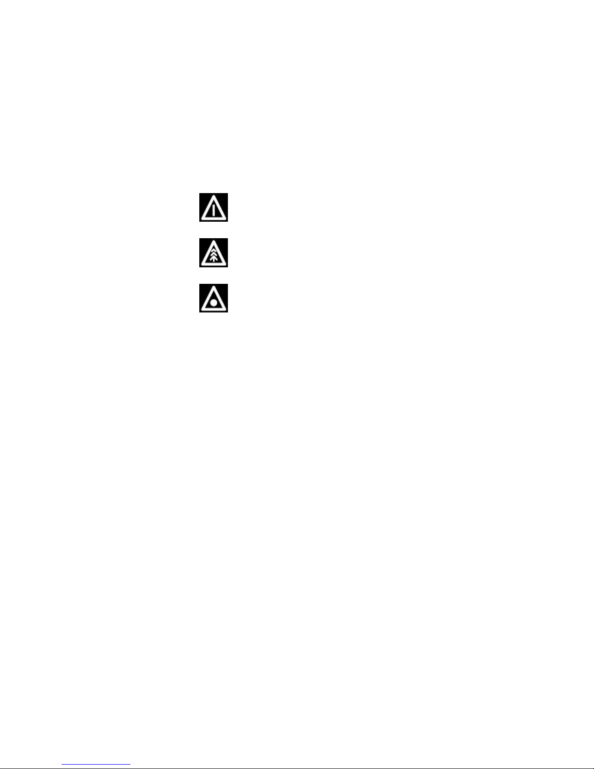
Personal safety
Failure to completely observe these instructions will result in serious risk of personal
injury.
Safeguarding the environment
Sections marked with this symbol indicate the correct use of the vehicle to prevent dam-
aging the environment.
Vehicle intactness
The incomplete or non-observance of these regulations leads to the risk of serious
damage to the vehicle and sometimes even the invalidity of the guarantee.
The signs that you see on this page are very important. They are used to highlight parts
of the booklet that should be read with particular care. The different symbols are used
to make each topic in the manual simple and quick to locate.
3

4

INDEX
VEHICLE...................................................................................... 7
Dashboard................................................................................ 8
Analogue instrument panel....................................................... 9
Digital lcd display...................................................................... 11
*MODE* button...................................................................... 12
Keyswitch.................................................................................. 13
Locking the steering wheel.................................................... 13
Releasing the steering wheel................................................ 13
Switch direction indicators........................................................ 14
Horn button............................................................................... 14
Light switch............................................................................... 15
Start-up button.......................................................................... 15
Engine stop button.................................................................... 16
System ABS.............................................................................. 16
System ASR.............................................................................. 17
The immobilizer system............................................................ 23
Keys...................................................................................... 23
Immobilizer device enabled indicator led.............................. 24
Operation............................................................................... 24
Programming the immobilizer system................................... 25
Accessing the fuel tank............................................................. 26
USB socket............................................................................... 27
Opening the saddle............................................................... 28
Identification.............................................................................. 29
Rear top box opening................................................................ 30
Bag clip..................................................................................... 31
USE.............................................................................................. 33
Checks...................................................................................... 34
Refuelling.................................................................................. 34
Tyre pressure............................................................................ 36
Shock absorbers adjustment.................................................... 37
Running in................................................................................. 38
Starting up the engine............................................................... 39
Precautions........................................................................... 40
Difficult start up......................................................................... 40
Stopping the engine.................................................................. 41
Stand......................................................................................... 42
Automatic transmission............................................................. 42
Safe driving............................................................................... 43
Rear rack.................................................................................. 45
MAINTENANCE........................................................................... 47
Engine oil level.......................................................................... 48
Engine oil level check............................................................ 48
Engine oil top-up................................................................... 49
Warning light (insufficient oil pressure)................................. 50
Engine oil change.................................................................. 50
Hub oil level.............................................................................. 51
Tyres......................................................................................... 53
Spark plug dismantlement........................................................ 55
Removing the air filter............................................................... 56
Cooling fluid level...................................................................... 56
Checking the brake oil level...................................................... 58
Battery....................................................................................... 59
Use of a new battery............................................................. 60
Long periods of inactivity.......................................................... 61
Fuses........................................................................................ 62
Lamps....................................................................................... 66
Front light group........................................................................ 67
Head light adjustment............................................................ 69
Front direction indicators........................................................... 70
Rear optical unit........................................................................ 71
Rear turn indicators................................................................... 72
Rear-view mirrors...................................................................... 73
Front and rear disc brake.......................................................... 73
Puncture.................................................................................... 74
Inactivity of the vehicle.............................................................. 75
5

Cleaning the vehicle.................................................................. 76
TECHNICAL DATA...................................................................... 81
SPARE PARTS AND ACCESSORIES........................................ 87
Warnings................................................................................... 88
SCHEDULED MAINTENANCE.................................................... 91
Scheduled servicing table......................................................... 92
Periodic maintenance table....................................................... 94
6

Vespa GTS 300 i.e. - Vespa GTS 300
i.e. ABS
Chap. 01
Vehicle
7
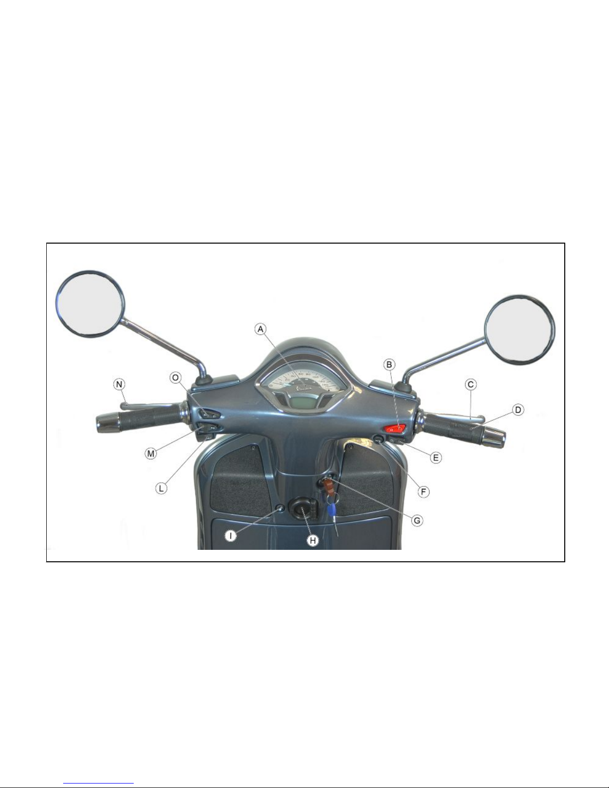
Dashboard (01_01)
01_01
8

A = Instrument panel
B = RUN/OFF switch
C = Front brake lever
D = Throttle grip
E = Starter button/Enabling-disabling button ASR system (where available)
F = MODE button
G = Ignition switch
H = Bag hook
I = Saddle opening button
L = Horn button
M = Turn indicator control
N = Rear brake lever
O = Light switch
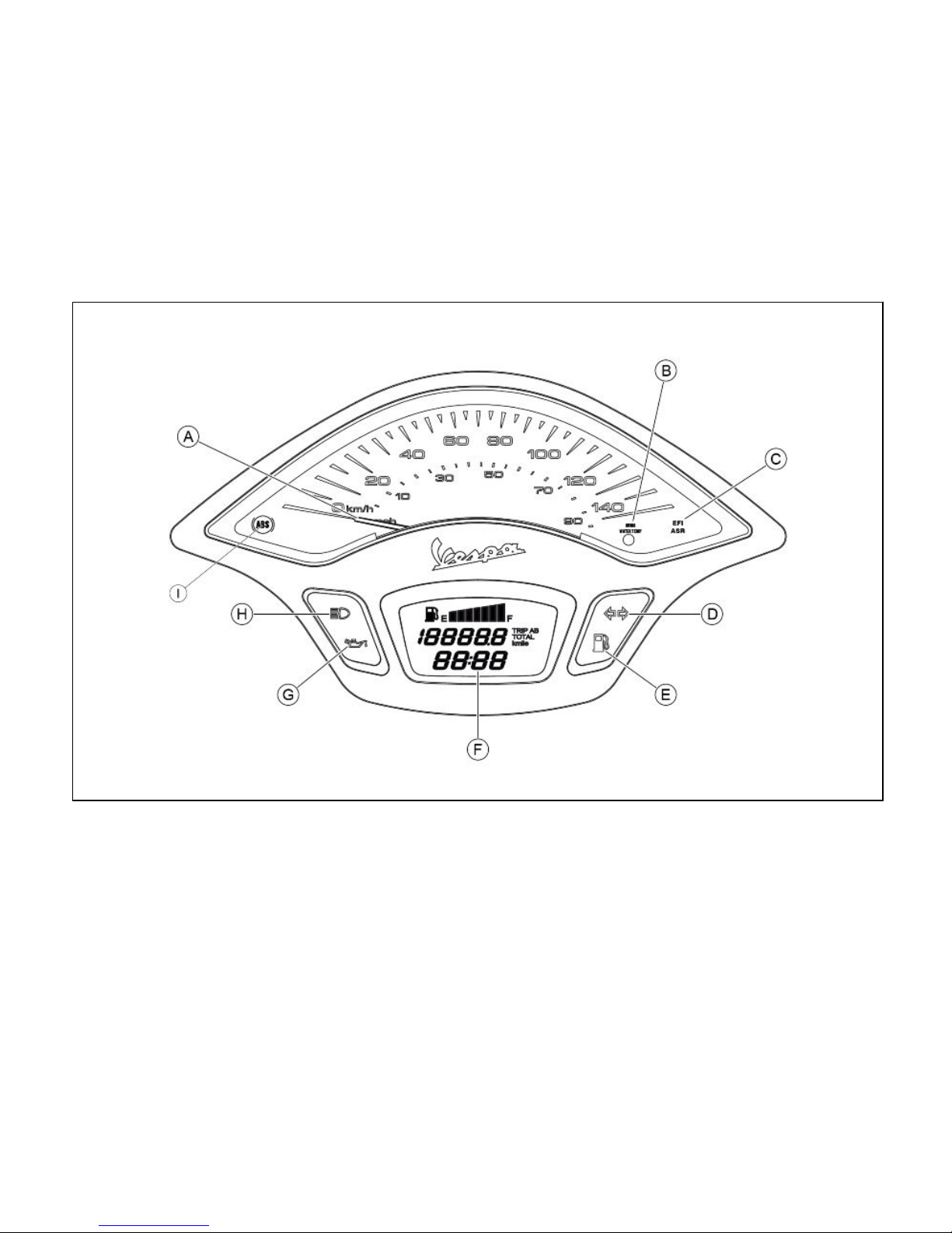
Analogue instrument panel (01_02)
9
1 Vehicle
01_02
A = Speedometer
B = Immobilizer warning light /engine temperature
10
C = Engine control warning light/ASR (where available)
D = Turn indicator warning light
E = Low fuel warning light
F= Digital display
G = Insufficient oil pressure warning light
H = High beam warning light
I = ABS warning light (where available)
01_03
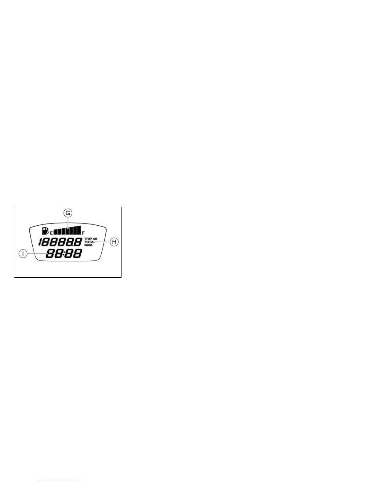
Digital lcd display (01_03)
G = Fuel gauge with petrol symbol
H = Total or partial odometer
I = Clock
By turning the ignition key to the «ON» position all the digital display functions will light
up for a few seconds.
MULTIFUNCTION INDICATOR «H»
Acting on the «MODE» button this indicator displays the following functions in sequence:
- Total odometer (TOTAL)
- Partial odometer A (TRIP A)
11
1 Vehicle
- Partial odometer B (TRIP B)
For this indicator, the unit of measurement can be changed (from Km to Miles) with
the following procedure:
- turn the key to the «OFF» position;
- press the «MODE» button;
- Holding in the «MODE» button, turn the key to the «ON» position;
- after about 2 seconds release the «MODE» button.
WARNING
TO GO FROM «KM» TO «MILE» THE MULTIFUNCTION INDICATOR «C» MUST
BE SET TO TOTAL ODOMETER (TOTAL).
N.B.
IN THE NAVIGATION OF THE DISPLAY ARE DEFINED:
- «BRIEF PRESS»: A PRESS OF THE INDICATED BUTTON, FOR A PERIOD OF
LESS THAN TWO SECONDS;
- «PROLONGED PRESS»: A PRESS OF THE INDICATED BUTTON, FOR A PERIOD OF MORE THAN TWO SECONDS.
01_04
*MODE* button (01_04)
With the vehicle running or with the key in position «ON», by short pressing the MODE
key «A», the odometer view can be changed (TOTAL, TRIP A, TRIP B).
By pressing and holding the MODE key, it is possible to:
- on the TOTAL screen page, proceed with adjusting the clock;
- on the TRIP A or TRIP B screen page, reset the relative counter.
12
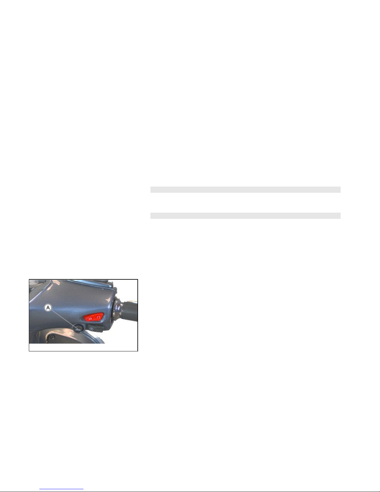
Keyswitch (01_05)
Ignition key «A» is located on the front leg shield back plate near the bag hook.
01_05
SWITCH POSITIONS
ON«1»: Ready to start position, non-extractable key, mechanical anti-theft device
disabled.
OFF «2»: Ignition disabled, extractable key, mechanical anti-theft device disabled.
LOCK «3»: Ignition disabled, extractable key, mechanical anti-theft device enabled.
Locking the steering wheel
Turn the handlebar to the left (as far as it will go), turn the key to «LOCK» and remove
the key.
CAUTION
NEVER TURN THE KEY TO «LOCK» OR «OFF» WHILE RIDING.
Releasing the steering wheel
Reinsert the key and turn it to «OFF».
13
1 Vehicle
CAUTION
NEVER TURN THE KEY TO «LOCK» OR «OFF» WHILE RIDING.
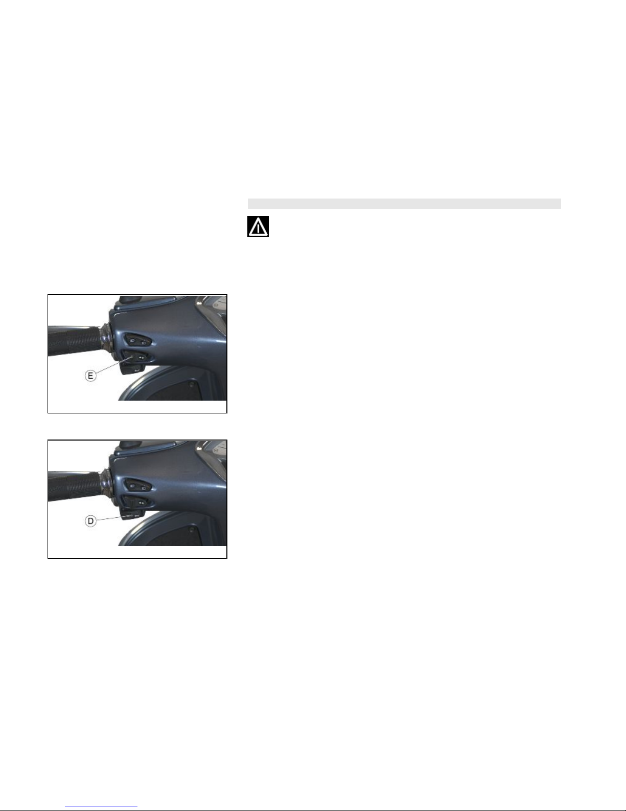
01_06
Switch direction indicators (01_06)
Move switch «E» to the left to indicate a left turn; move switch «E» to the right to
indicate a right turn. Push the central part of switch «E» to deactivate the turn indicators.
01_07
Horn button (01_07)
Push the button «D» to sound the horn.
14
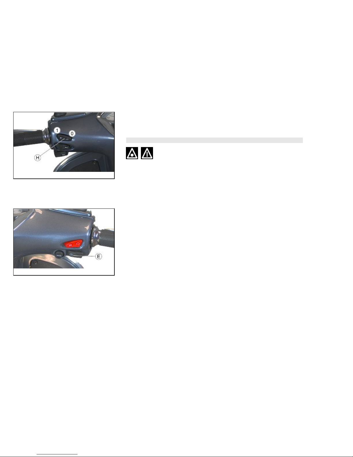
01_08
Light switch (01_08)
When the light switch «H» is set to «0», the low-beam light is on. When set to «1»,
the high-beam light is activated.
CAUTION
DO NOT PLACE, TRANSPORT OBJECTS AND/OR CLOTHES OVER THE FRONT
HEADLIGHT ASSEMBLY, WHEN THE HEADLIGHT IS TURNED ON OR OFF.
FAILURE TO FOLLOW THIS PRECAUTION MAY CAUSE OVERHEATING AND
THE SUBSEQUENT FUSION OF THE GLASS.
01_09
Start-up button (01_09)
Starter button «E»
15
1 Vehicle
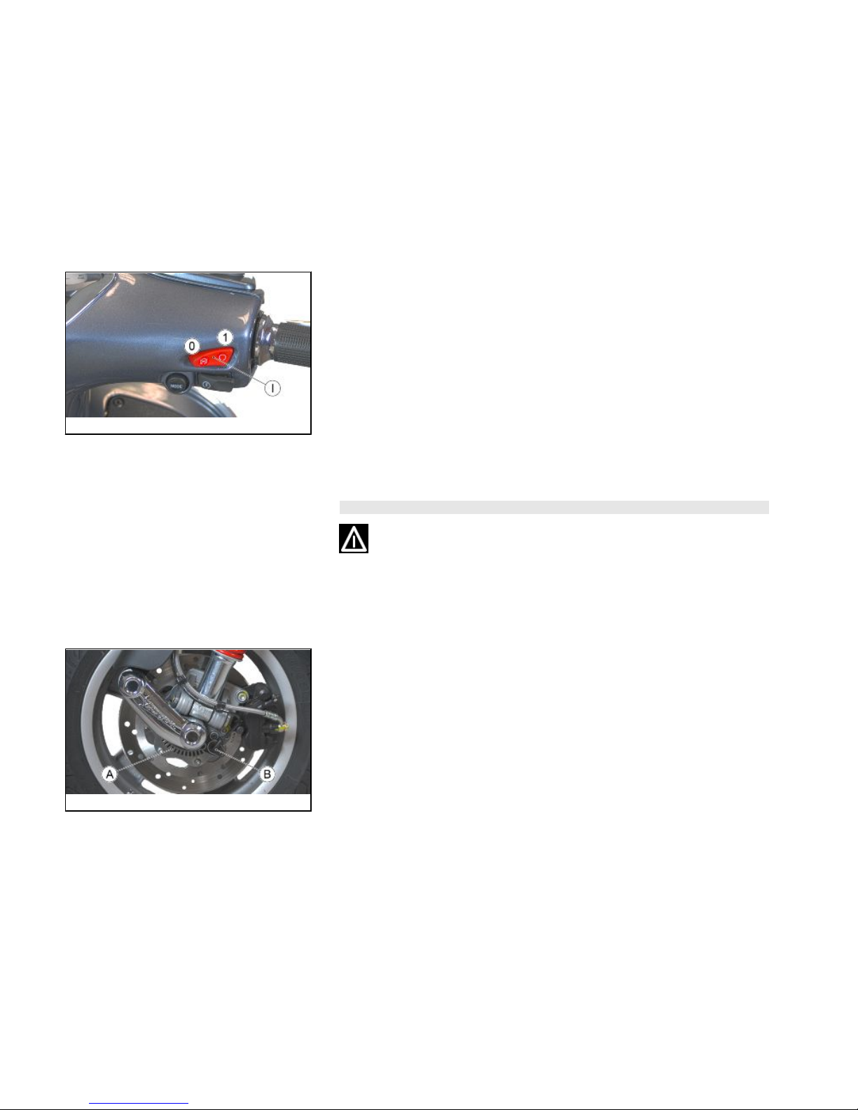
01_10
Engine stop button (01_10)
The engine can be started when the emergency cut-off switch «I» is set to «1»
RUN; if the emergency cut-off switch «I» is set to «0» OFF, the engine cannot be
started, or it shuts off if already running.
System ABS (01_11, 01_12)
WARNING
DEPENDING ON THE PURCHASED VERSION THE VEHICLE IS EQUIPPED WITH
THE ABS SYSTEM. THE INDICATIONS SHOWN BELOW ARE TO REFER TO FOR
VEHICLES WITH ABS SYSTEM, IT IMPROVES THE SAFETY DURING BRAKING
BY AVOIDING THAT THE WHEELS BLOCK.
01_11
The vehicle is equipped with a locking ABS system on the wheels.
A: Tone wheel
B: Speed sensor
•
ABS: It is a hydraulic - electronic device that limits the pressure within the
braking circuit when a sensor, located on the wheel, detects its tendency to
lock. This system prevents the wheels from locking to avoid the risk of falling.
In case of failure of the ABS system, immediately reported to the rider with ABS warning light on the instrument panel, the vehicle retains the characteristics of a conventional braking system. In case of ABS warning light, reduce speed and go to an
16
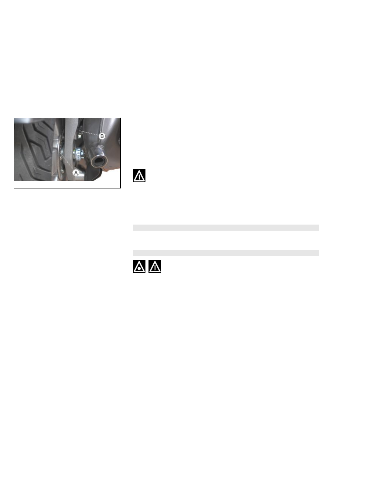
01_12
Authorised Service Centre for the appropriate checks. The safety provided by the ABS
does not, in any case, justify risky manoeuvres. The stopping distance may be greater,
compared to a conventional vehicle equipped with traditional braking in the following
conditions:
•
Riding on rough roads, with gravel or snow
•
Riding on roads with holes or bumps
It is therefore recommended to reduce speed in these conditions.
AT VERY LOW SPEEDS (LESS THAN 5 KM/H) THE ABS SYSTEM IS DISABLED.
IT IS RECOMMENDED TO PAY ATTENTION THEREFORE IN CASES OF BRAK-
ING IN LOW GRIP CONDITIONS AT LOW SPEED (FOR EXAMPLE BRAKING ON
GARAGE FLOOR TILES AFTER HAVING RIDDEN ON WET ROADS OR SIMILAR
SITUATIONS)
N.B.
THE ABS WARNING LIGHT TURNS ON AND STAYS ON UNTIL REACHING 5 KM/
H.
CAUTION
IN THE EVENT OF MALFUNCTION OF THE BATTERY, THE ABS - ASR SYSTEM
TURNS OFF.
System ASR (01_13, 01_14)
ASR SYSTEM
The ASR system is a device to help riding that helps the rider during acceleration
manoeuvres, especially on slippery surfaces or in conditions that can cause sudden
17
1 Vehicle
slippage of the rear wheel. The ASR in these situations automatically intervenes by
reducing engine output within the limit imposed by the grip conditions, contributing
significantly to the maintenance of stability the vehicle.
WARNING
THE ASR SYSTEM IS BASED ON THE RECOGNITION OF SPEED DIFFERENCES
BETWEEN FRONT AND REAR WHEEL. IN ORDER FOR THE SYSTEM TO MAINTAIN MAXIMUM EFFICIENCY IN ALL CONDITIONS, THE CALIBRATION PROCEDURE
MUST BE PERFORMED EVERY TIME, EVEN IN CASE OF REPLACE-
MENT OF JUST ONE TYRE.
FOR THE CALIBRATION OF THE CONTROL UNIT PERFORM THE PROCEDURE
BELOW.
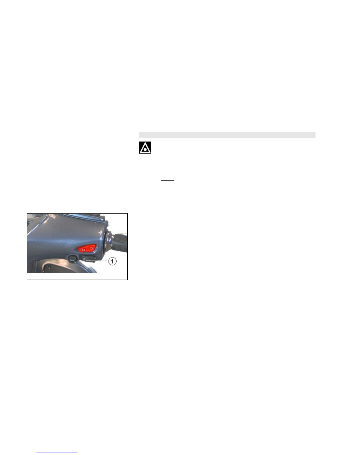
01_13
•
BUTTON «1» (with the engine running): on / off.
•
ASR/EFI WARNING LIGHT «2»:ASR and EFI operating indication warning
light (engine malfunction).
18

01_14
N.B.
THE WARNING LIGHT PERFORMS AN INITIAL CHECK AT KEY ON; AFTER-
WARDS OPERATE AS DESCRIBED AS FOLLOWS.
N.B.
THE ENGINE MALFUNCTION (EFI) HAS PRIORITY OVER THE ASR FUNCTION.
WARNING
UNDER NORMAL OPERATING CONDITIONS (ASR ENGAGED), THE ENGINE
MALFUNCTION WARNING LIGHT IS OFF.
CAUTION
WHEN THE WARNING LIGHT FLASHES WITH A FREQUENCY OF 1 FLASH PER
SECOND (1 HZ), THERE IS AN ENGINE MALFUNCTION. SHOULD THIS HAPPEN,
CONTACT AN AUTHORISED SERVICE CENTRE.
Flashing mode:
-
Frequency of 5 flashes per second (5Hz), with vehicle running: the system is up and
running (conditions of low grip and intervention to reduce engine power); we recommend the utmost caution because the grip limit has been exceeded; restore the vehicle
safety conditions by gently reducing the throttle opening.
19
1 Vehicle
- Frequency of 2 flashes per second (2 Hz), with vehicle running: the system is in
calibration phase; for the specific procedure refer to the following.
- Lit with moving vehicle: the system is disabled and will not intervene in case of loss
of grip.
•
If the deactivation was voluntary (by pressing the appropriate button «1» for
1 second with the engine running) it is recommended to reactivate the system
as soon as possible.
•
If the deactivation was NOT voluntary, there is an ASR failure: in this case
you must contact an Authorised Service Centre for the diagnosis and the
reactivation of the system.
To ensure maximum safety of the vehicle it is advisable to keep the system active.
Deactivation may be necessary only in case of starting with very low grip surfaces
(mud, snow) on which the operation of the ASR could actually prevent the movement
of the vehicle.
WARNING
THE ASR SYSTEM IS ACTIVATED AT EVERY «ON» POSITIONING OF THE IGNITION SWITCH.
IF DISABLED BY THE USER, THE ASR SYSTEM KEEPS THE STATE OF INACTIVITY ONLY IF THE VEHICLE IS OFF, BY USING THE ENGINE STOP SWITCH;
AT THE NEXT KEY ON THE ASR SYSTEM IS ENABLED AUTOMATICALLY.
CAUTION
IT IS EMPHASISED THAT THE RIDING AUXILIARY SYSTEM CAN NOT CHANGE
THE PHYSICAL LIMITS OF GRIP AND IS NOT A SUBSTITUTE FOR PROPER
MANAGEMENT OF POWER, BOTH ON STRAIGHT STRETCHES AND IN TURNS.
THEREFORE, IT IS RECOMMENDED TO ALWAYS USE THE VEHICLE WITH THE
UTMOST CARE AND IN ACCORDANCE WITH THE REGULATIONS IN FORCE.
20
CAUTION
AT LOW SPEED (LESS THAN 5 KM/H), THE ASR SYSTEM DOES NOT WORK.
IT IS RECOMMENDED TO PAY PARTICULAR ATTENTION IN THE EVENT OF
ACCELERATION FROM STANDSTILL IN CONDITIONS OF LOW GRIP, ESPECIALLY IN THE FIRST METRES.
N.B.
IN CASE OF ROADS FULL OF HOLES THERE MAY OCCUR BRIEF ACTIVATION
OF THE ASR SYSTEM. THIS OCCURS UNDER NORMAL OPERATING CONDITIONS OF THE VEHICLE.
N.B.
THE DEVICE PREVENTS IMPRESSING ON THE REAR HIGH SPEED ROTATION
WHEEL WITH THE VEHICLE ON THE CENTRE STAND. IT IS RECOMMENDED
NOT TO INSIST WITH THE THROTTLE GRIP IN THIS PARTICULAR CONDITION.
CAUTION
A POOR STATE OF MAINTENANCE OF THE TYRES CAN RESULT IN ABNORMAL OPERATION OF THE ASR SYSTEM.
IN CASE OF REPEATED INTERVENTIONS OF THE ASR, EVEN ON ROAD SURFACES WITH GOOD GRIP OR SMALL THROTTLE OPENINGS, IT IS NECESSARY
TO CHECK FOR WEAR AND/OR THE STATE OF INFLATION OF TYRES FIRST.
IF THE PROBLEM PERSISTS, CONTACT AN AUTHORISED SERVICE CENTRE.
21
1 Vehicle
CAUTION
IN THE EVENT OF MALFUNCTION OF THE BATTERY, THE ABS - ASR SYSTEM
TURNS OFF.
ASR SYSTEM CALIBRATION PROCEDURE.
In order to maintain the effectiveness of the ASR system following the replacement of
one or both tyres a calibration procedure of the system must be performed as follows
on a straight flat stretch of road. Please note that the request for activation of the
procedure (steps 1 to 4) must be completed within 60 sec from ignition on the engine.
• It is necessary that the diagnostic phase of the ASR systems and ABS is complete:
for this purpose, after the key ON, ride a short distance above 5 km/h and wait for the
flashing of the EFI/ASR warning light to stop.
• Turn the ASR system off by pressing the button «1» on the handlebar and check that
the ASR disabling warning light «2» is on.
• Allow the engine to idle for at least 3 seconds.
• Press the ASR on/off button «1» and one of the two brake levers simultaneously for
at least 4 seconds. The activation of the procedure will be confirmed by lighting up of
the EFI/ASR warning light «2» with a frequency of 2 flashes per second (2 Hz).
• Accelerate to a constant speed of 30 to 40 km/h and maintain it for at least 7 to 8
seconds.
• The end of the procedure will be indicated by the flashing EFI/ASR warning light
«2».
• Once the procedure is complete it is necessary to turn off the vehicle panel (key off)
and wait 30 seconds before turning the panel on (key on).
• In case of failure to complete the procedure within 2 minutes the EFI/ASR warning
light «2» will stay on steady and the ASR will remain off until the panel is turned off
(key off).
22
• To restart the ASR it is necessary to turn on vehicle panel (key on).
It is however necessary to repeat the process until it succeeds.
CAUTION
IF NECESSARY, CONTACT AN AUTHORISED SERVICE CENTRE.
The immobilizer system
In order to enhance theft protection, the vehicle is equipped with a «PIAGGIO IMMOBILIZER » electronic engine locking device that is activated automatically when the
ignition key is removed. Upon start-up, the «PIAGGIO IMMOBILIZER» system checks
the starter key, and only if this key is recognised will the Immobiliser system allow the
vehicle to be started.
01_15
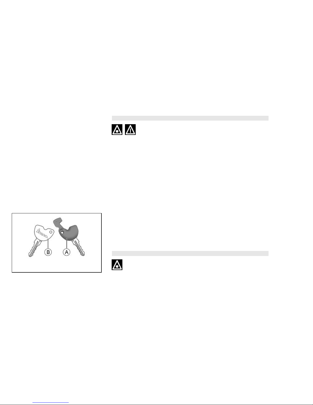
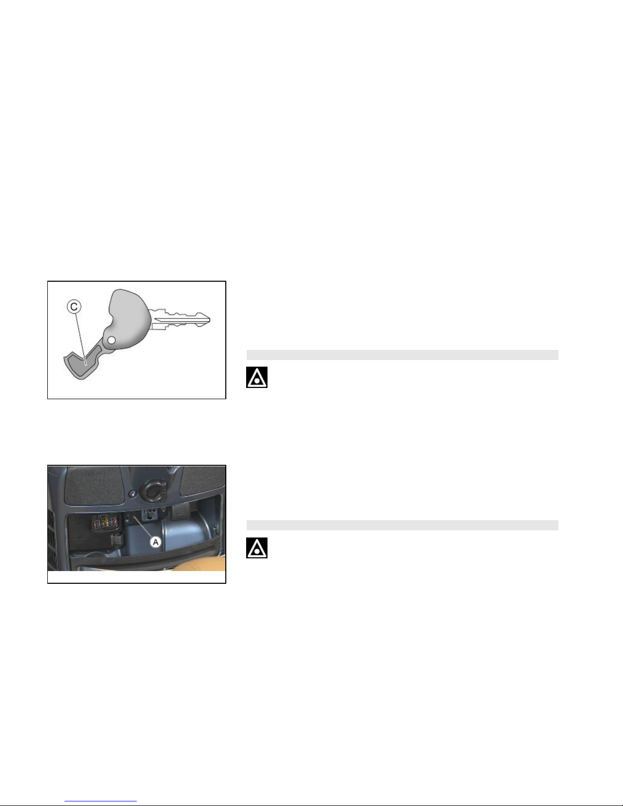
Keys (01_15)
The vehicle is supplied with two types of keys. The «A» key with a brown grip and the
"MASTER" key. Only a single copy of this key is supplied, which is necessary to program all the other keys and for the dealer to perform some maintenance operations.
We therefore recommend that it be used only under exceptional circumstances. The
blue key «B» (single copy supplied) is used for normal operations and for start-up.
WARNING
THE LOSS OF THE BROWN KEY PREVENTS LATER REPAIRS TO THE "PIAGGIO IMMOBILIZER" SYSTEM AND TO THE ENGINE CONTROL UNIT.
23
1 Vehicle
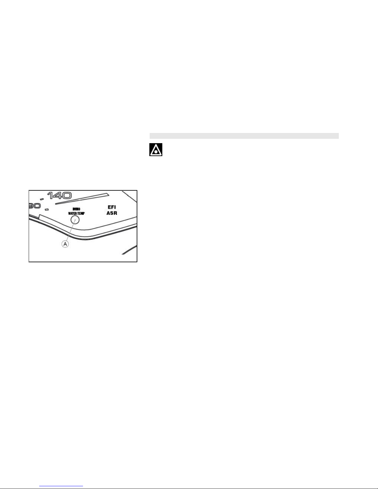
Immobilizer device enabled indicator led (01_16)
CAUTION
WITH THE ENGINE RUNNING, THE WARNING LIGHT «A» HAS THE FUNCTION
TO SIGNAL THE ENGINE COOLANT TEMPERATURE. REFER TO THE SECTION
«MAINTENANCE» / «COOLANT LEVEL».
01_16
Activation of the "PIAGGIO IMMOBILIZER" system is signalled by a flashing «A»
indicator. In order to reduce battery discharge, the indicator LED turns off automatically
after 48 hours of uninterrupted functioning. Should the system fail, different LED flashing patterns will provide the Authorised Service Centre with information on the type
of fault detected.
Operation
Every time the ignition key is removed in the "OFF" or "LOCK" position, the safety
system activates the immobilizer system. Turning the key to "ON" disables the engine
lock, provided that the safety system recognises the code transmitted by the key. If
the code is not recognised, turn the key first to "OFF" and then to "ON"; if the lock
cannot be disabled, try with the other key supplied (brown). If the engine cannot be
started, contact an Authorised Piaggio Service Centre, which is provided with the
electronic equipment required to detect and repair the system. The Immobilizer is also
activated by switching off the engine with the RUN OFF switch. This happens even if
the starter key is in «ON».
When additional keys are required, please note that data storage (up to 7 keys max.)
must be done on all keys, both new and existing ones. Take the key with the brown
grip and all the blue keys supplied to an Authorised Piaggio Service Centre. The
24
codes of keys not submitted for the new programming procedure are deleted from the
memory. Any lost keys will therefore not be enabled to start the engine.
WARNING
EACH KEY HAS ITS OWN AND UNIQUE CODE, WHICH MUST BE STORED IN
THE SYSTEM CONTROL UNIT MEMORY.
VIOLENT SHOCKS MAY AFFECT THE ELECTRONIC COMPONENTS OF THE
KEY.
SHOULD THE VEHICLE CHANGE OWNER, IT IS ABSOLUTELY NECESSARY
THAT THE NEW OWNER GET POSSESSION OF THE KEY WITH THE BROWN
GRIP (AS WELL AS ALL OTHER KEYS).
Programming the immobilizer system (01_17)
Below is described the procedure to follow for programming the PIAGGIO IMMOBILISER system and/or for storing other key codes. The programming procedure should
be carried out with the engine stop switch set to «RUN».
START PROCEDURE
Insert the «MASTER» key «A» into the ignition switch (in «OFF») and turn it to
«ON». After 1 - 3 seconds, turn the key to «OFF » again and pull it out.
INTERMEDIATE STAGE
After extracting the «MASTER» key «A», insert, within ten seconds, the key that is
going to be programmed «B» and turn it immediately to «ON». After 1-3 seconds, turn
the key to «OFF» again and pull it out. In this way, a maximum of 7 keys can be
programmed by repeating the above procedure and keeping the indicated times.
25
1 Vehicle
FINAL STAGE
After extracting the key to be programmed «B», insert the «MASTER» key «A» again
and turn it to «ON» (perform this operation within the 10 seconds following the extraction of the previous key). Leave it in this position for 1 to 3 seconds and return it
to «OFF».
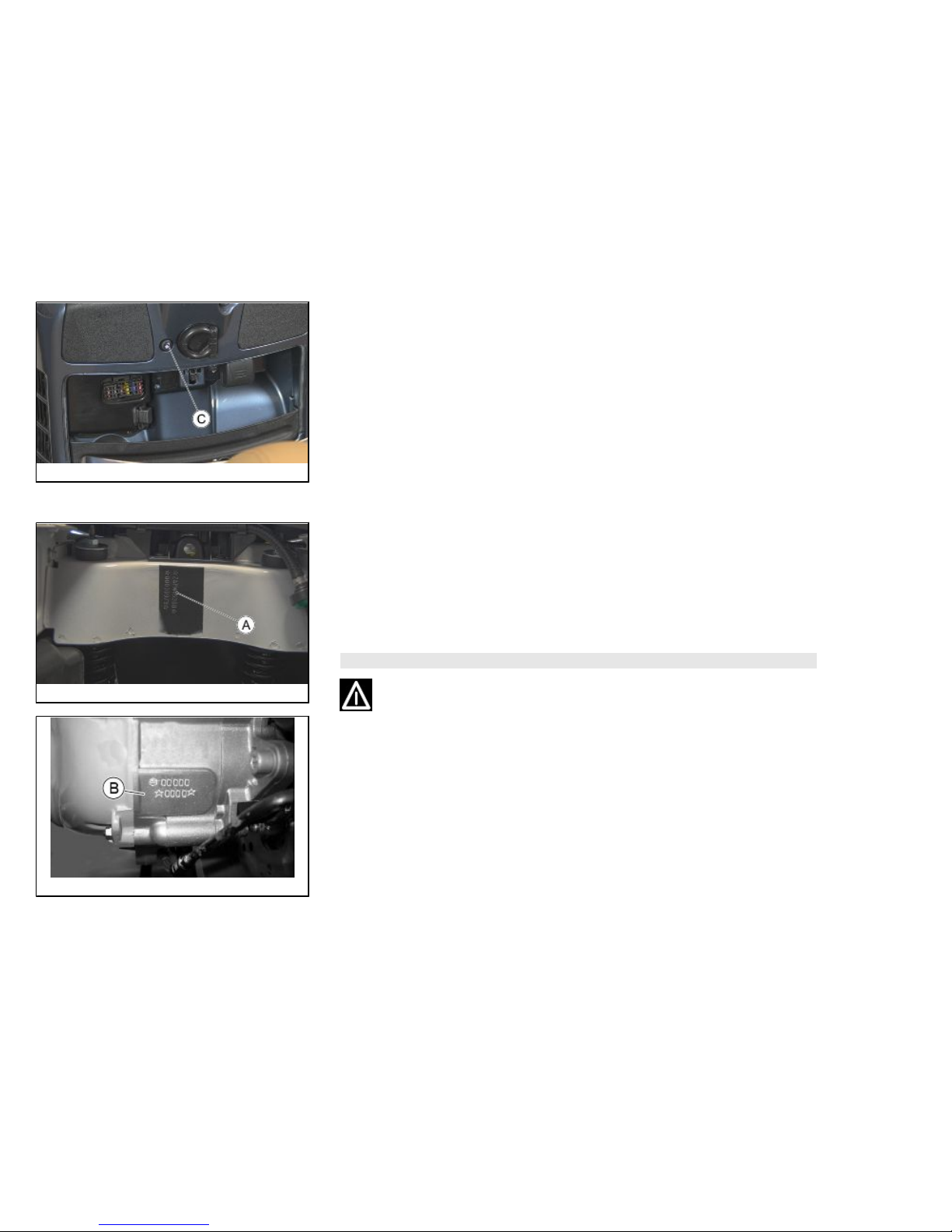
01_17
CORRECT PROGRAMMING CHECK PHASE
Insert the «MASTER» key «A» disabling the transponder «C» (i.e., by tilting the key
cap by 90°), and turn the key to «ON». Perform the engine starter operation. Ensure
that the engine does not start. Insert the programmed key «B» and repeat the starter
operation. Check that engine starts.
WARNING
SHOULD YOU START THE ENGINE WITH THE MASTER KEY (WITH TRANSPONDER OFF) OR IN THE EVENT OF WRONG OPERATION DURING PROGRAMMING, REPEAT THE PROCEDURE FROM THE BEGINNING.
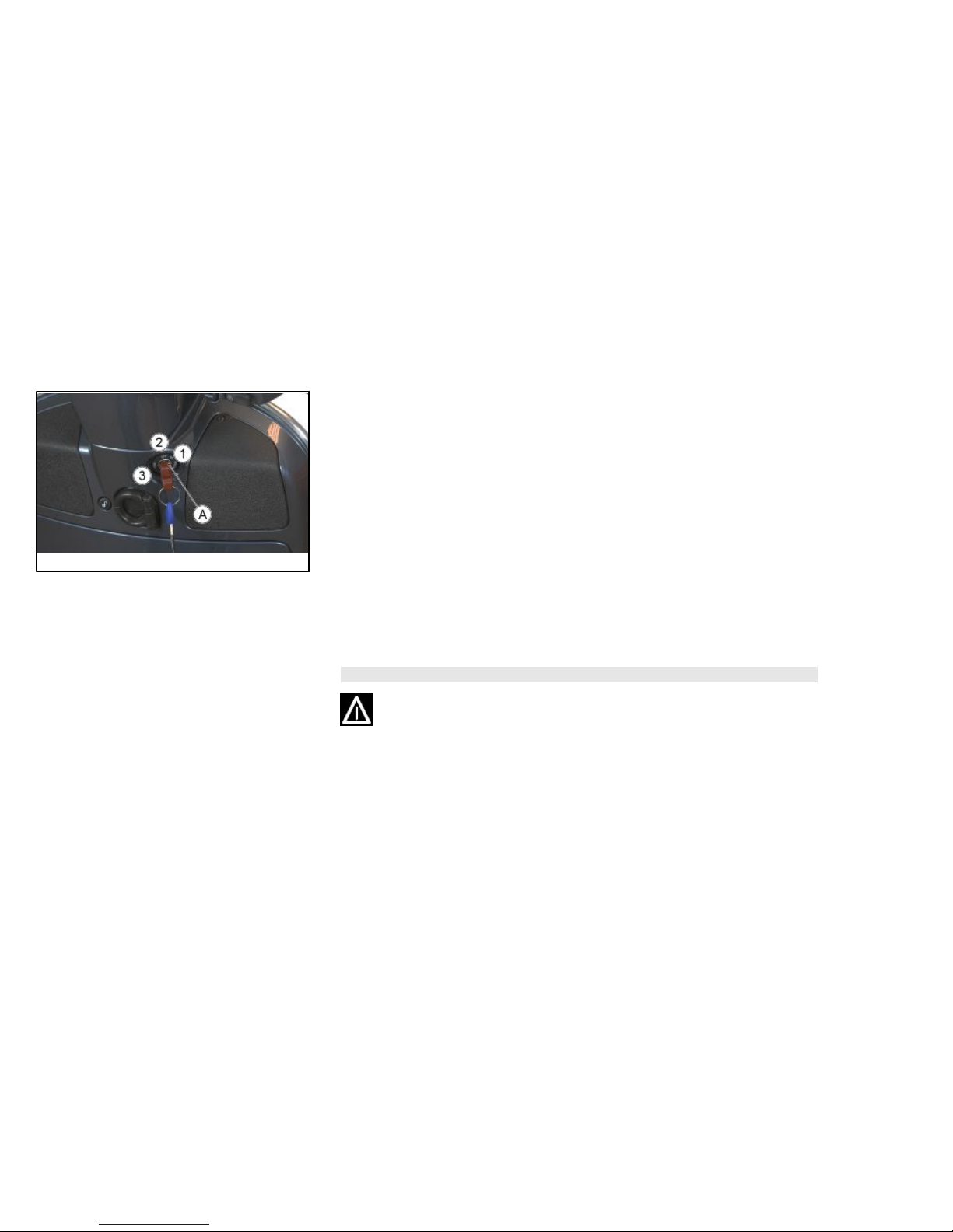
01_18
Accessing the fuel tank (01_18, 01_19)
With the key in the «OFF» or «ON» position, or with the engine running it is possible
to electrically open the saddle by pressing the «C» button. In case of failure of the
electrical opening, operate the emergency lever «A».
CAUTION
ALWAYS USE PETROL WITH A MAXIMUM OF 10% BIOETHANOL CONTENT
(E10).
26
01_19
DO NOT USE PETROL WITH AN ETHANOL CONTENT HIGHER THAN 10%; THIS
USE COULD DAMAGE THE FUEL SYSTEM COMPONENTS AND/OR COMPROMISE ENGINE PERFORMANCE.
01_20
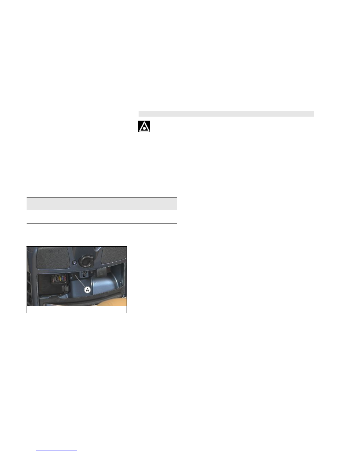
USB socket (01_20)
Inside the front glove compartment on the left side, in the versions where available, is
a USB plug «A».
To use it, remove the protective cap. Cover the socket again with the cap to avoid that
water and/or humidity could damage it.
CAUTION
THE SUPPLIED USB SOCKET IS COMPATIBLE WITH THE DEVICES OF THE
FOLLOWING BRANDS: Apple iPhone, Apple iPod, Apple iPod Nano, Apple iPod
Touch, Blackberry Pearl, Blackberry 8xxx AND NOT COMPATIBLE WITH THE
DEVICES FOR THE PRODUCTS OF THE MOTOROLA BRAND.
The USB socket is active once the key is turned to «ON».
27
1 Vehicle
CAUTION
PROLONGED USE OF THE PLUG SOCKET MAY RESULT IN PARTIAL DISCHARGE OF THE BATTERY
USB PORT
USB port
Output voltage (5.00±0.25) Vdc
Charging current 1 A max
01_21
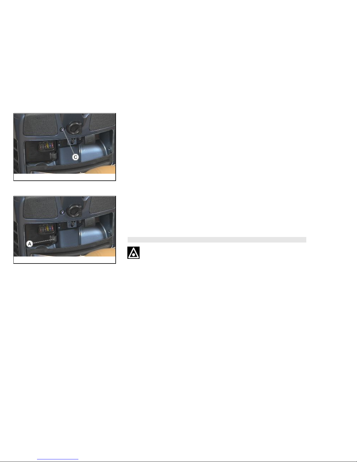
Opening the saddle (01_21, 01_22)
With the key set to «OFF» or «ON», or with engine on, it is possible to electrically open
the saddle by pressing button «C». If the electric opening does not work, use the
emergency lever "A". When the key is set to «LOCK» the saddle cannot be opened.
28
01_22
01_23
01_24
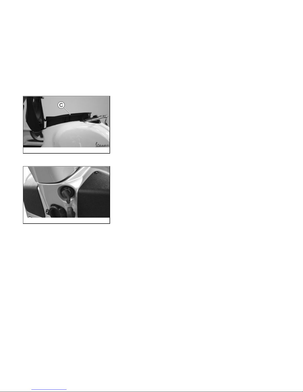
Identification (01_23, 01_24, 01_25)
The identification registration numbers consist of a prefix followed by a number stamped on both the chassis «A» and the engine «B». These numbers must always be
indicated on spare parts requests. To read the chassis number, lift the saddle and
remove the helmet compartment «C». We recommend checking that the chassis registration number stamped on the vehicle corresponds with that on the vehicle documentation.
CAUTION
PLEASE REMIND THAT ALTERING IDENTIFICATION REGISTRATION NUMBERS CAN LEAD TO SERIOUS PENAL SANCTIONS (IMPOUNDING OF THE
VEHICLE, ETC.).
29
1 Vehicle
01_25
01_26
Rear top box opening (01_26)
Insert the key into the switch and press down until the glove compartment opens. If
the switch is set to "LOCK", turn the key to "OFF" or "ON" before pressing it down.
30
 Loading...