

Page 1
WORKSHOP MANUAL
633338
Vespa GT 125-200
Page 2

WORKSHOP
MANUAL
Vespa GT 125-200
The descriptions and illustrations given in this publication are not binding. While the basic specifications
as described and illustrated in this manual remain unchanged, PIAGGIO-GILERA reserves the right, at
any time and without being required to update this publication beforehand, to make any changes to
components, parts or accessories, which it considers necessary to improve the product or which are
required for manufacturing or construction reasons.
Not all versions/models shown in this publication are available in all countries. The availability of single
versions should be checked at the official Piaggio sales network.
"© Copyright 2007 - PIAGGIO & C. S.p.A. Pontedera. All rights reserved. Reproduction of this publication
in whole or in part is prohibited."
PIAGGIO & C. S.p.A. - After-Sales
V.le Rinaldo Piaggio, 23 - 56025 PONTEDERA (Pi)
Page 3
WORKSHOP MANUAL
Vespa GT 125-200
This workshop manual has been drawn up by Piaggio & C. Spa to be used by the workshops of PiaggioGilera dealers. This manual is addressed to Piaggio service mechanics who are supposed to have a
basic knowledge of mechanics principles and of vehicle fixing techniques and procedures. Any important
changes made to the vehicles or to specific fixing operations will be promptly reported by updates to this
manual. Nevertheless, no fixing work can be satisfactory if the necessary equipment and tools are
unavailable. It is therefore advisable to read the sections of this manual relating to specific tools, along
with the specific tool catalogue.
N.B. Provides key information to make the procedure easier to understand and carry out.
CAUTION Refers to specific procedures to carry out for preventing damages to the vehicle.
WARNING Refers to specific procedures to carry out to prevent injuries to the repairer.
Personal safety Failure to completely observe these instructions will result in serious risk of personal
injury.
Safeguarding the environment Sections marked with this symbol indicate the correct use of the vehicle
to prevent damaging the environment.
Vehicle intactness The incomplete or non-observance of these regulations leads to the risk of serious
damage to the vehicle and sometimes even the invalidity of the guarantee.
Page 4
INDEX OF TOPICS
CHARACTERISTICS CHAR
TOOLING TOOL
MAINTENANCE MAIN
TROUBLESHOOTING TROUBL
ELECTRICAL SYSTEM ELE SYS
ENGINE FROM VEHICLE ENG VE
ENGINE ENG
SUSPENSIONS SUSP
BRAKING SYSTEM BRAK SYS
COOLING SYSTEM COOL SYS
CHASSIS CHAS
PRE-DELIVERY PRE DE
TIME TIME
Page 5

INDEX OF TOPICS
CHARACTERISTICS CHAR
Page 6

Characteristics Vespa GT 125-200
This section describes the general specifications of the vehicle.
Rules
This section describes general safety rules for any maintenance operations performed on the vehicle.
Safety rules
- If work can only be done on the vehicle with the engine running, make sure that the premises are wellventilated, using special extractors if necessary; never let the engine run in an enclosed area. Exhaust
fumes are toxic.
- The battery electrolyte contains sulphuric acid. Protect your eyes, clothes and skin. Sulphuric acid is
highly corrosive; in the event of contact with your eyes or skin, rinse thoroughly with abundant water
and seek immediate medical attention.
- The battery produces hydrogen, a gas that can be highly explosive. Do not smoke and avoid sparks
or flames near the battery, especially when charging it.
- Fuel is highly flammable and it can be explosive given some conditions. Do not smoke in the working
area, and avoid naked flames or sparks.
- Clean the brake pads in a well-ventilated area, directing the jet of compressed air in such a way that
you do not breathe in the dust produced by the wear of the friction material. Even though the latter
contains no asbestos, inhaling dust is harmful.
Maintenance rules
- Use original PIAGGIO spare parts and lubricants recommended by the Manufacturer. Non-original or
non-conforming spares may damage the vehicle.
- Use only the appropriate tools designed for this vehicle.
- Always use new gaskets, sealing rings and split pins upon refitting.
- After removal, clean the components using non-flammable or low flash-point solvents. Lubricate all
the work surfaces, except tapered couplings, before refitting these parts.
- After refitting, make sure that all the components have been installed correctly and work properly.
- For removal, overhaul and refit operations use only tools with metric measures. Metric bolts, nuts and
screws are not interchangeable with coupling members with English sizes. Using unsuitable coupling
members and tools may damage the scooter.
- When carrying out maintenance operations on the vehicle that involve the electrical system, make
sure the electric connections have been made properly, particularly the ground and battery connections.
Vehicle identification
Granturismo 125
Chassis prefix: ZAPM311000000 ÷ 1001
CHAR - 6
Page 7

Vespa GT 125-200 Characteristics
Engine prefix: M311M1001
Granturismo 200
Chassis prefix: ZAPM312000000 ÷ 1001
Engine prefix: M312M1001
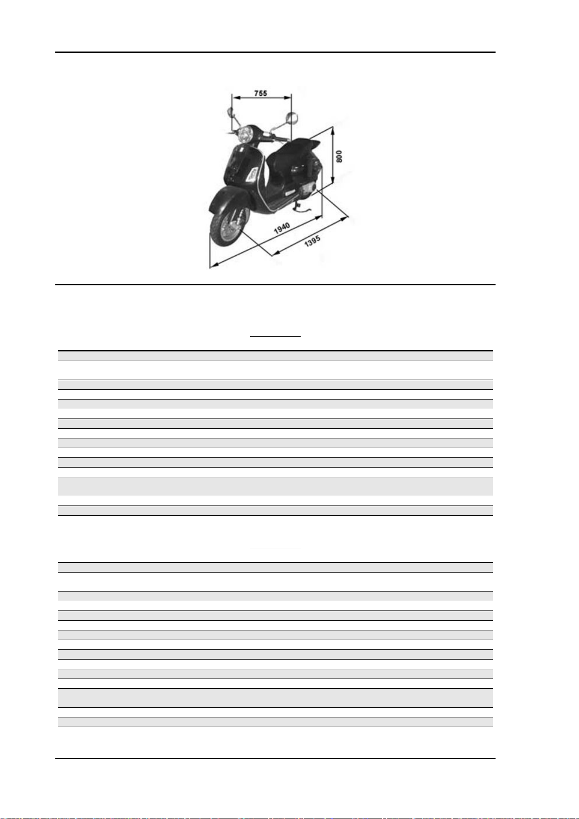
Dimensions and mass
Specification
Total loadless weight 140 Kg
Width (to hand grips) 755 mm
Length 1940 mm
Wheelbase 1395 mm
Saddle height 800 mm
MASS AND DIMENSIONS
Desc./Quantity
CHAR - 7
Page 8
Characteristics Vespa GT 125-200
Engine
DATA 125
Specification Desc./Quantity
Type single-cylinder, four-stroke and four liquid-cooled valves
Timing system single overhead camshaft chain driven on the left-hand side, 3-
Bore 125 57 mm
Stroke 48.6 mm
Piston displacement 125 124,015 cm3
Compression ratio 125 12 ÷ 13 : 1
Walbro Carburettor 125 WVF-7G
Keihin Carburettor 125 CVK 30
Engine idle speed 1650 ± 50 rpm
CO value 3,8 ± 0,7 %
Air filter sponge, impregnated with mixture (50% petrol and 50% oil)
Start-up system electric starter motor (engine 200 cc with torque limiter)
Lubrication with lobe pump (inside the crankcase) controlled by a chain and
Fuel supply petrol, with vacuum pump and through carburettor
Max power (shaft) 125 11 kW (15 cv) at 9,700 rpm
Max speed 125 104 Km/h
arm rocking levers set up with set screw
double filter: mesh and paper
DATA 200
Specification
Type single-cylinder, four-stroke and four liquid-cooled valves
Timing system single overhead camshaft chain driven on the left-hand side, 3-
arm rocking levers set up with set screw
Bore 200 72 mm
Stroke 48.6 mm
Piston displacement 200 197,775 cm3
Compression ratio 200 11 ÷ 12 : 1
Walbro Carburettor 200 WVF-7P
Keihin Carburettor 200 CVK 30
Engine idle speed 1650 ± 50 rpm
CO value 3,8 ± 0,7 %
Air filter sponge, impregnated with mixture (50% petrol and 50% oil)
Start-up system electric starter motor (engine 200 cc with torque limiter)
Lubrication with lobe pump (inside the crankcase) controlled by a chain and
Fuel supply petrol, with vacuum pump and through carburettor
Max power (shaft) 200 15.4 kW (21 cv) at 8,500 rpm
Max speed 200 125 Km/h
Desc./Quantity
double filter: mesh and paper
CHAR - 8
Page 9

Vespa GT 125-200 Characteristics
Transmission
TRANSMISSION
Specification Desc./Quantity
Transmission Automatic expandable pulley variator with torque server, V belt,
Capacities
CAPACITY
Specification Desc./Quantity
Engine oil ~ 1000 cc (recommended oil: Selenia HI Scooter 4 Tech)
Fuel tank (including a ~ 2 l reserve) ~ 9.5 l
Rear hub 150 cc (recommended oil: TUTELA ZC 90)
Cooling system fluid approx. 2.100 ÷ 2.150 l PARAFLU 11FE (Diluted)
automatic clutch, gear reduction unit and transmission housing
with forced air circulation cooling
Electrical system
Specification
Type of ignition Electronic capacitive discharge ignition, with variable timing
Variable spark advance (before T.D.C.) 125 from 10° ± 1° to 2,000 rpm at 34° ± 1° to 6,000 rpm
Spark plug 125 Champion RG 4 HC
Battery 12V/ 12 Ah
Fuses N° 1 15A, N° 1 10A, N° 3 7,5A, N° 2 5A
Generator alternating current
Specification
Type of ignition Electronic capacitive discharge ignition, with variable timing
Variable ignition advance (before TDC) 200 from 10° ± 1° at 2000 rpm to 32° ± 1° at 6500 rpm
Spark plug 200 CHAMPION RG 6 YC
Battery 12V/ 12 Ah
Fuses N° 1 15A, N° 1 10A, N° 3 7,5A, N° 2 5A
Generator alternating current
Frame and suspensions
ELECTRIC COMPONENTS 125
Desc./Quantity
and separate HV coil
ELECTRIC COMPONENTS 200
Desc./Quantity
and separate HV coil
FRAME AND SUSPENSIONS
Specification
Type Unitised body made of stamped plate
Front suspension Single arm suspension (cantilever wheel) fitted with a double-
acting hydraulic shock absorber with coaxial spring
Front shock absorber axial travel 86.5 mm
Rear suspension Engine with swinging fork articulated to frame by means of an
arm with 2 degrees of freedom Pair of double-acting hydraulic
shock absorbers and coaxial springs with preloading adjust-
Rear shock absorber axial travel 89.5 mm
Desc./Quantity
ment in 4 positions.
CHAR - 9
Page 10

Characteristics Vespa GT 125-200
Brakes
BRAKES
Specification Desc./Quantity
Front Ø 220 disc brake and floating calliper with Ø 25 mm twin plung-
Rear Ø 220 disc brake and calliper with two Ø 30 mm counteracting
ers and hydraulic control (lever on the far right end of the
handlebar)
plungers and hydraulic control (lever on the far left end of the
handlebar)
Wheels and tyres
WHEELS AND TYRES
Specification Desc./Quantity
Front wheels - light alloy rims 3.00x12
Rear wheels - light alloy rims 3.00x12
Front tyres 120/70-12" Tubeless
Rear tyres 130/70-12" Tubeless
TYRE PRESSURE
Specification
Front tyre pressure (when cold) 1.8 bar
Rear tyre pressure (when cold) 2 bar
Tyre pressure (when cold) with passenger 2.2 bar
N.B.
CHECK AND ADJUST TYRE PRESSURE WITH TYRES AT AMBIENT TEMPERATURE. REGULATE PRESSURE ACCORDING TO THE WEIGHT OF THE RIDER AND ACCESSORIES
Desc./Quantity
Carburettor
125cc Version
Kehin
KEHIN CARBURETTOR 125
Specification
Depression carburettor CVEK-30
Body stamping CVEK
CUT-OFF device Not present
Max. jet 98
Minimum jet 38
Max.air jet 150
Minimum air jet 130
Throttle valve spring 100 ÷ 160 g
Minimum mixture set screw initial opening 2 ± ¼
Tapered pin NDVA
Tapered pin notches from top Single-notch pin
Diffuser nozzle Ø 5.0
Petrol inlet hole -
Starter air jet Ø 1.5
Starter diffuser nozzle -
Starter jet 42
Diameter of starter pin -
Starter device resistance ~ 20 Ω
Desc./Quantity
CHAR - 10
Page 11

Vespa GT 125-200 Characteristics
Specification Desc./Quantity
Venturi diffuser Ø 29 (47x30.9)
Throttle valve Ø 30.5
Diffuser maximum cone -
N.B.
* THE IDENTIFICATION LETTER MAY VARY WITH EACH CARBURETTOR UPDATE.
Walbro
WALBRO CARBURETTOR 125
Specification Desc./Quantity
Depression type WVF-7R*
Printing on the body 7R1
CUT-OFF device Not. pres.
Max jet 103
Minimum jet 38
Max air jet 60
Minimum air jet 110
Throttle valve spring 100 g
Idle mixture adjustment screw initial opening 2 7/8 ± 1/2
Conical pin 653
Conical pin top notches 2
Diffuser nozzle Ø 2.7
Gasoline inlet hole Ø 1.5
Starter air jet 200
Starter diffuser jet 130
Starter jet 48
Starter pin diameter Ø 1,78
Starter device resistance ~ 40 Ω
Venturi diffuser Ø 29 (30.3x27)
Throttle valve Ø 33
Choke maximum cone Ø 48,0
N.B.
* THE IDENTIFICATION LETTER MAY VARY WITH EACH CARBURETTOR UPDATE.
200cc Version
Kehin
Idle mixture adjustment screw initial opening 2 1/4 ± 1/4
Conical pin top notches Single notch pin
Starter emulsifier jet -
Starter pin diameter -
Starter device resistance ~ 20 Ω
KEHIN CARBURETTOR 200
Specification
Depression type CVEK 30
Body stamping CVK
CUT-OFF device Present
Max jet 92
Minimum jet 38
Max air jet 70
Minimum air jet 115
Gas valve spring 0,150 - 0,250 Kgf
Conical pin NDAA
Diffuser nozzle Ø 5.0
Fuel inlet hole -
Starter air jet Ø 1.5
Starter jet 42
Desc./Quantity
CHAR - 11
Page 12

Characteristics Vespa GT 125-200
Specification Desc./Quantity
Venturi choke Ø 29 (47x30,9)
Throttle valve Ø 30,5
Choke maximum cone -
N.B.
THE IDENTIFICATION LETTER CAN VARY WITH EACH CARBURETTOR UPDATE
Walbro
WALBRO CARBURETTOR 200
Specification Desc./Quantity
Depression type WVF-7P*
Printing on the body 7P
CUT-OFF device Present
Max jet 95
Minimum jet 33
Max air jet 120
Minimum air jet 55
Gas valve spring 120 gr
Idle mixture adjustment screw initial opening 2 ± 1/2
Conical pin 495
Conical pin top notches 2
Diffuser nozzle Ø 2.7
Gasoline inlet hole Ø 1.5
Starter air jet 200
Starter emulsifier jet 110
Starter nozzle 45
Starter pin diameter Ø 1,78
Starter device resistance ~ 40 Ω
Venturi diffuser Ø 29 (30.3x27)
Throttle valve Ø 33
Choke maximum cone Ø 48,0
N.B.
THE IDENTIFICATION LETTER CAN VARY WITH EACH CARBURETTOR UPDATE
Tightening Torques
STEERING ASSEMBLY
Name
Upper steering ring nut 30 ÷ 40
Lower steering ring nut 8 ÷ 10
Handlebar fixing screw 45 ÷ 50 (The two screws must be tightened to the prescribed
torque after having done so with the rear wheel axle nut. Safety
locks: see «Pre-delivery Operations» )
Fixing screws for handlebar control assembly U-bolts 7 ÷ 10
FRAME ASSEMBLY
Name
Engine-swinging arm bolt 64 - 72
swinging arm bolt - body shell 76 ÷ 83
Engine and vehicle side swinging arm junction bolt 33 ÷ 41
Bolt of the Silent block support plate 42 ÷ 52
Centre stand bolt 25 - 30
Side stand fixing bolt 40 ÷ 45
FRONT SUSPENSION
Name
Screw fixing the shock absorber to the shock absorber - calliper
attachment plate
Wheel axle nut 75 ÷ 90
Torque in Nm
Torque in Nm
Torque in Nm
20 ÷ 27
CHAR - 12
Page 13

Vespa GT 125-200 Characteristics
Name Torque in Nm
Wheel screw 20 ÷ 25
Screw fixing rear mudguard to steering 5 ÷ 6.5
FRONT BRAKE
Name Torque in Nm
Brake fluid pump-hose fitting 20 ÷ 25
Brake fluid hose-calliper fitting 20 ÷ 25
Screw fixing calliper to the shock absorber - calliper plate at-
tachment
Disc tightening screw 6 (Apply LOCTITE 242 threadlock, medium strength)
Oil bleed screw 12 - 16
Pad fastening pin 19.6 ÷ 24.5
Brake pump reservoir screws 15 ÷ 20
REAR SUSPENSION
Name Torque in Nm
Retainer for left shock absorber to crankcase support plate 20 ÷ 25
Shock absorber upper fitting 20 ÷ 25
Shock absorber lower fitting 33 ÷ 41
Rear wheel axle 104 ÷ 126
Screw fixing wheel to hub 20 ÷ 25
Screws for muffler - shock absorber support arm on engine 20 ÷ 25 (The two screws must be tightened to the prescribed
torque after having done so with the rear wheel axle nut. Safety
locks: see «Pre-delivery Operations» )
20 ÷ 25
REAR BRAKE
Name
Brake fluid pump-hose fitting 20 ÷ 25
Brake fluid pipe-calliper fitting 20 ÷ 25
Rear disc tightening bolt 11 ÷ 13
Oil bleed screw 12÷16
Calliper to engine tightening screw 20 ÷ 25
Brake pump reservoir screws 15 ÷ 20
Calliper coupling screws 30 ÷ 33
Torque in Nm
MUFFLER
Name
Muffler heat guard clamping screw 5 - 6
Exhaust fumes inlet screw 13 ÷ 15
Screw for fixing muffler to the support arm 20 ÷ 25
Torque in Nm
LUBRICATION
Name
Hub oil drainage plug 15 ÷ 17
Oil filter on crankcase fitting 27 ÷ 33
Engine oil drainage plug/mesh filter 24 ÷ 30
Oil filter 8 ÷ 10
Oil pump cover screws 7 ÷ 9
Screws fixing oil pump to crankcase 5 - 6
Oil pump control crown screw 10 ÷ 14
Oil pump cover plate screws 4 ÷ 6
Oil sump screws 10 ÷ 14
Minimum oil pressure sensor 12 ÷ 14
Torque in Nm
CYLINDER HEAD
Name
Spark plug 12 ÷ 14
Head cover screws 6 ÷ 7
Nuts for head fastening to the cylinder 7± 1 + 180° (2x90°) (Fasten nuts in two crossed passes) (Be-
fore fitting the nuts, lubricate them with engine oil.)
Head fixing side screws 11 ÷ 13
Starter ground screw 7 ÷ 8.5
Torque in Nm
CHAR - 13
Page 14
Characteristics Vespa GT 125-200
Name Torque in Nm
Side screw M5 locking the washers on the camshaft (125 cc) 7 ÷ 8,5
Tappet set screw lock nut 6 ÷ 8
Inlet manifold screws 11 ÷ 13
Timing chain tensioner slider screw 10 ÷ 14
Start up mass bell screws (200 cc) 11 ÷ 15
Central screw M6 locking the washers on the camshaft (125
cc)
Timing chain tensioner support screw 11 ÷ 13
Timing chain tensioner central screw 5 - 6
Camshaft retention plate screw 4 ÷ 6
11 ÷ 15
TRANSMISSION
Name Torque in Nm
Belt support roller screw 11 ÷ 13
Clutch assembly nut on driven pulley 55 ÷ 60
Drive pulley nut 75 ÷ 83
Transmission cover screws 11 ÷ 13
Driven pulley shaft nut 54 ÷ 60
Rear hub cap screws 24 ÷ 27
FLYWHEEL
Name Torque in Nm
Flywheel cover fixing screws 5 - 6
Stator assembly screws 3 - 4 (Apply LOCTITE 242 medium-strength threadlock)
Flywheel nut 52 ÷ 58
Pick-Up clamping screws 3 ÷ 4
CRANKCASE AND CRANKSHAFT
Name
Internal engine crankcase bulkhead (transmission-side half
shaft) screws
Engine-crankcase coupling screws 11 ÷ 13
Starter motor screws 11 ÷ 13
Crankcase timing cover screws 3.5 - 4.5 (Apply LOCTITE 242 medium-strength threadlock)
Name
Water pump rotor cover 3 ÷ 4
Screws of the water pump rotor driving link 3 ÷ 4
Thermostat cover screws 3 ÷ 4
Overhaul data
Assembly clearances
Torque in Nm
4 ÷ 6
COOLING
Torque in Nm
CHAR - 14
Page 15
Vespa GT 125-200 Characteristics
Cylinder - piston assy.
ENGINE 125 COUPLING CATEGORIES
Name
Cylinder A 56.997 ÷ 57.004 56.945 ÷ 56.952 0.045 - 0.059
Cylinder B 57.004 ÷ 57.011 56.952 ÷ 56.959 0.045 - 0.059
Piston C 57.011 ÷ 57.018 56.959 ÷ 56.966 0.045 - 0.059
Piston D 57.018 ÷ 57.025 56.966 ÷ 56.973 0.045 - 0.059
Cylinder 1st Oversize A1 57.197 ÷ 57.204 57.145 ÷ 57.152 0.045 - 0.059
Cylinder 1st Oversize B 1 57.204 ÷ 57.211 57.152 ÷ 57.159 0.045 - 0.059
Piston 1st Oversize C 1 57.211 ÷ 57.218 57.159 ÷ 57.166 0.045 - 0.059
Piston 1st Oversize D 1 57.218 ÷ 57.225 57.166 ÷ 57.173 0.045 - 0.059
Cylinder 2nd Oversize A2 57.397 ÷ 57.404 57.345 ÷ 57.352 0.045 - 0.059
Cylinder 2nd Oversize B 2 57.404 ÷ 57.411 57.352 ÷ 57.359 0.045 - 0.059
Piston 2nd Oversize C 2 57.411 ÷ 57.418 57.359 ÷ 57.366 0.045 - 0.059
Piston 2nd Oversize D 2 57.418 ÷ 57.425 57.366 ÷ 57.373 0.045 - 0.059
Cylinder 3rd Oversize A 3 57.597 ÷ 57.604 57.545 ÷ 57.552 0.045 - 0.059
Cylinder 3rd Oversize B 3 57.604 ÷ 57.611 57.552 ÷ 57.559 0.045 - 0.059
Piston 3rd Oversize C 3 57.611 ÷ 57.618 57.559 ÷ 57.566 0.045 - 0.059
Piston 3rd Oversize D 3 57.618 ÷ 57.625 57.566 ÷ 57.573 0.045 - 0.059
Initials Cylinder Piston Play on fitting
CHAR - 15
Page 16
Characteristics Vespa GT 125-200
ENGINE 200 COUPLING CATEGORIES
Name
Cylinder / piston A 71.990 ÷ 71.997 71.953 ÷ 71.960 0.030 - 0.044
Cylinder / piston B 71.997 ÷ 72.004 71.960 ÷ 71.967 0.030 - 0.044
Cylinder / piston C 72.004 ÷ 72.011 71.967 ÷ 71.974 0.030 - 0.044
Cylinder / piston D 72.011 ÷ 72.018 71.974 ÷ 71.981 0.030 - 0.044
Initials Cylinder Piston Play on fitting
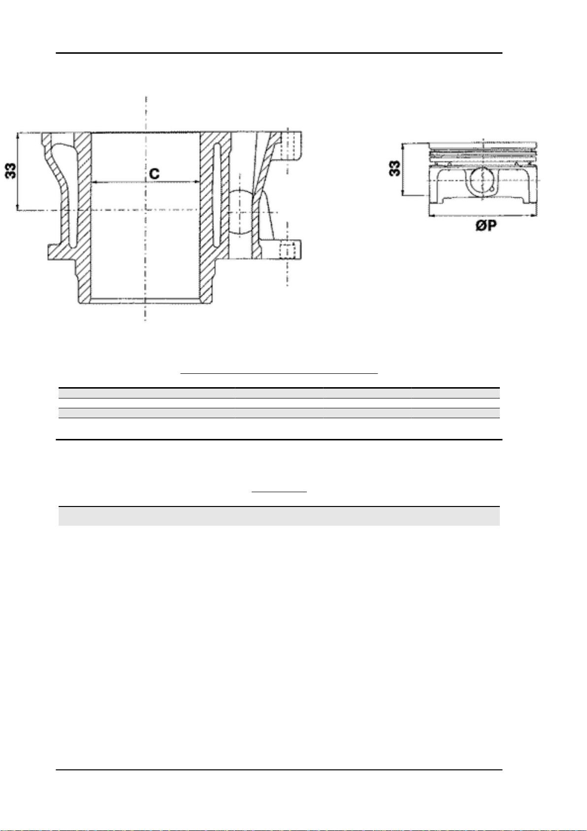
Crankcase - crankshaft - connecting rod
CRANKSHAFT
Titolo
Crankshaft Crankshaft to crankcase axial
Crankshaft to crankcase axial clearance
Durata/Valore Testo Breve (< 4000 car.) Indirizzo Immagine
clearance
CHAR - 16
Page 17
Vespa GT 125-200 Characteristics
CRANKSHAFT/ CRANKCASE AXIAL CLEARANCE
Name
Half-shaft, transmission
side
Flywheel-side half-shaft 16.6 +0-0.05 B D = 0.20 - 0.50
Connecting rod 18 -0.10 -0.15 C D = 0.20 - 0.50
Spacer tool 51.4 +0.05 E D = 0.20 - 0.50
Description Dimensions Initials Quantity
16.6 +0-0.05 A D = 0.20 - 0.50
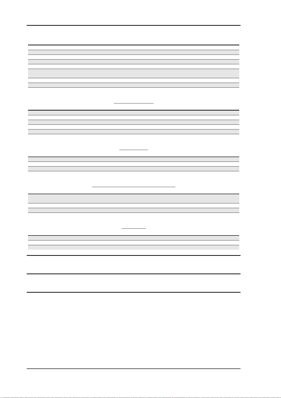
Slot packing system
Characteristic
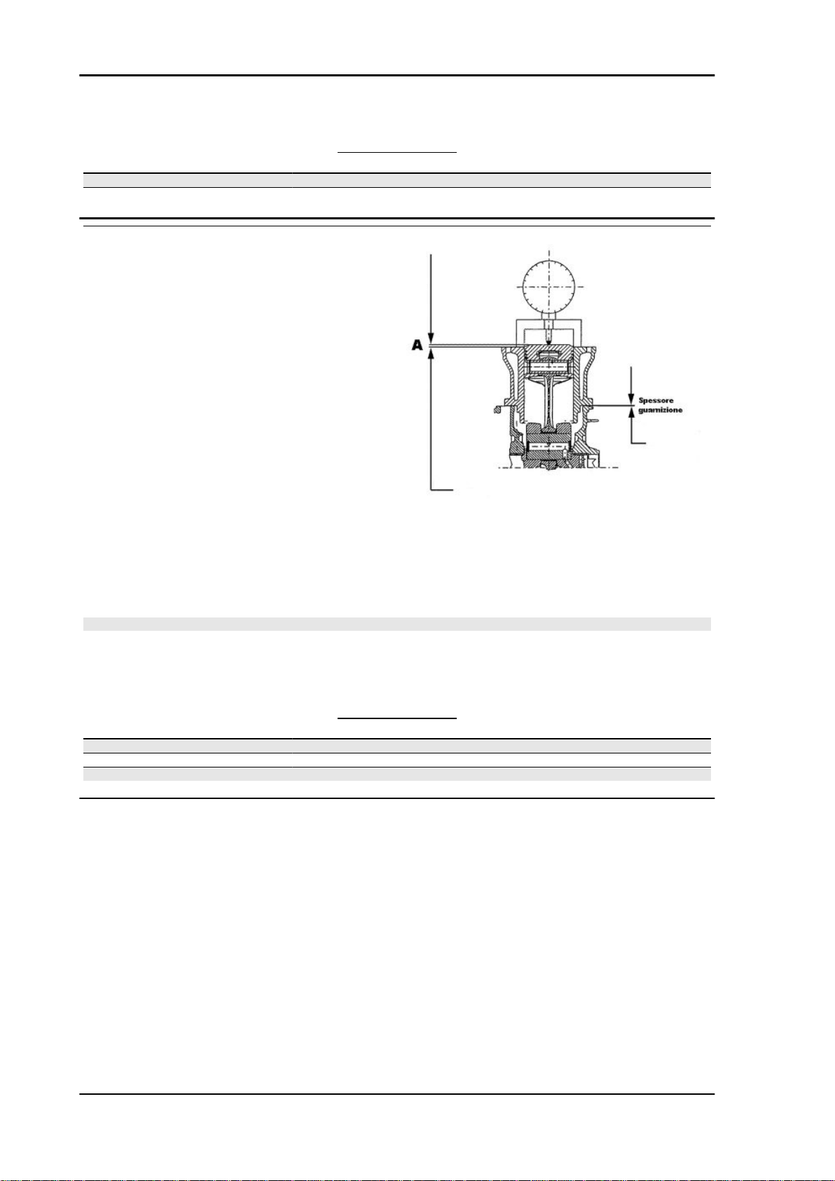
Shimming system for limiting the compression
ratio 125
Rc = 12 ÷ 13 : 1
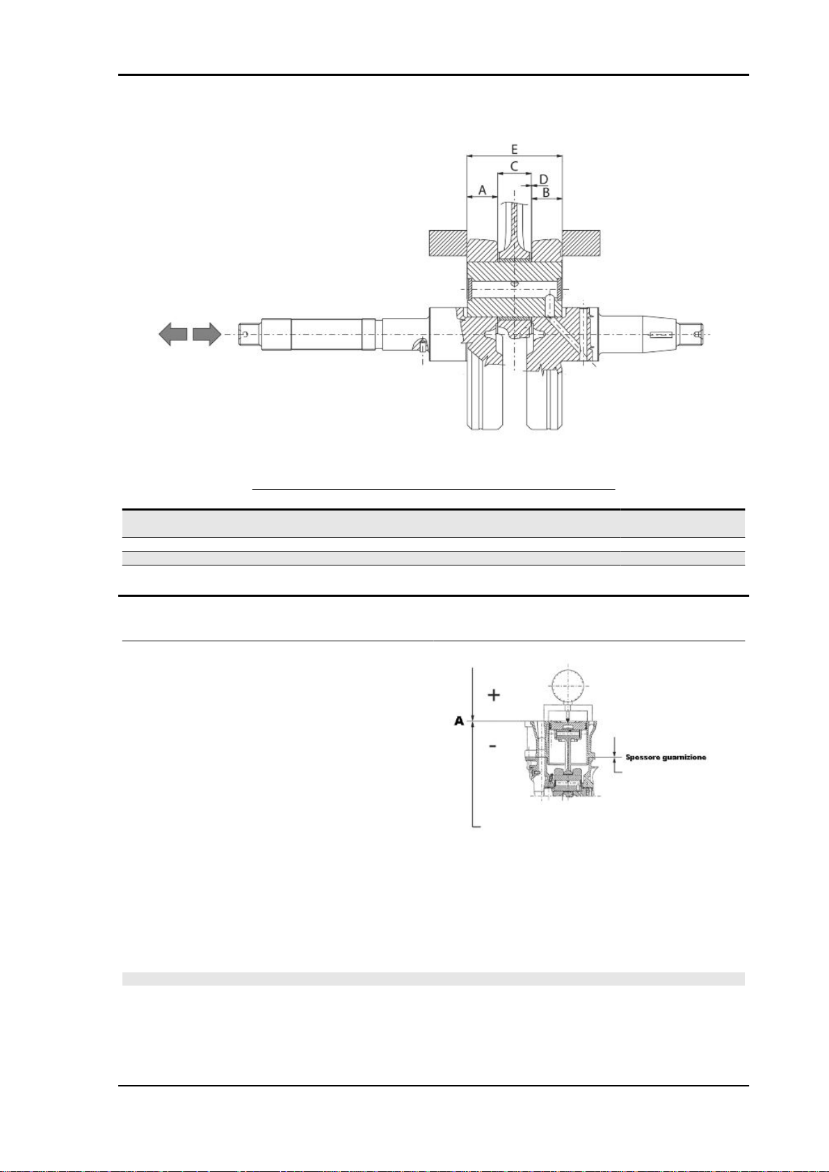
Measurement "A" to be taken is a value of piston protrusion. It indicates by how much the plane formed
by the piston crown protrudes from the plane formed by the upper part of the cylinder. The further the
piston protrudes from the cylinder, the bigger the base gasket to be used (to recover the compression
ratio) and vice versa.
N.B.
DISTANCE "A" MUST BE MEASURED WITHOUT ANY GASKET FITTED BETWEEN CRANKCASE
AND CYLINDER
CHAR - 17
Page 18
Characteristics Vespa GT 125-200
THICKNESS 125
Name Measure A Thickness
Gasket thickness 125 2,2 ÷ 2,4 0,4 ± 0,05
Gasket thickness 125 2,4 ÷ 2,6 0,6 ± 0,05
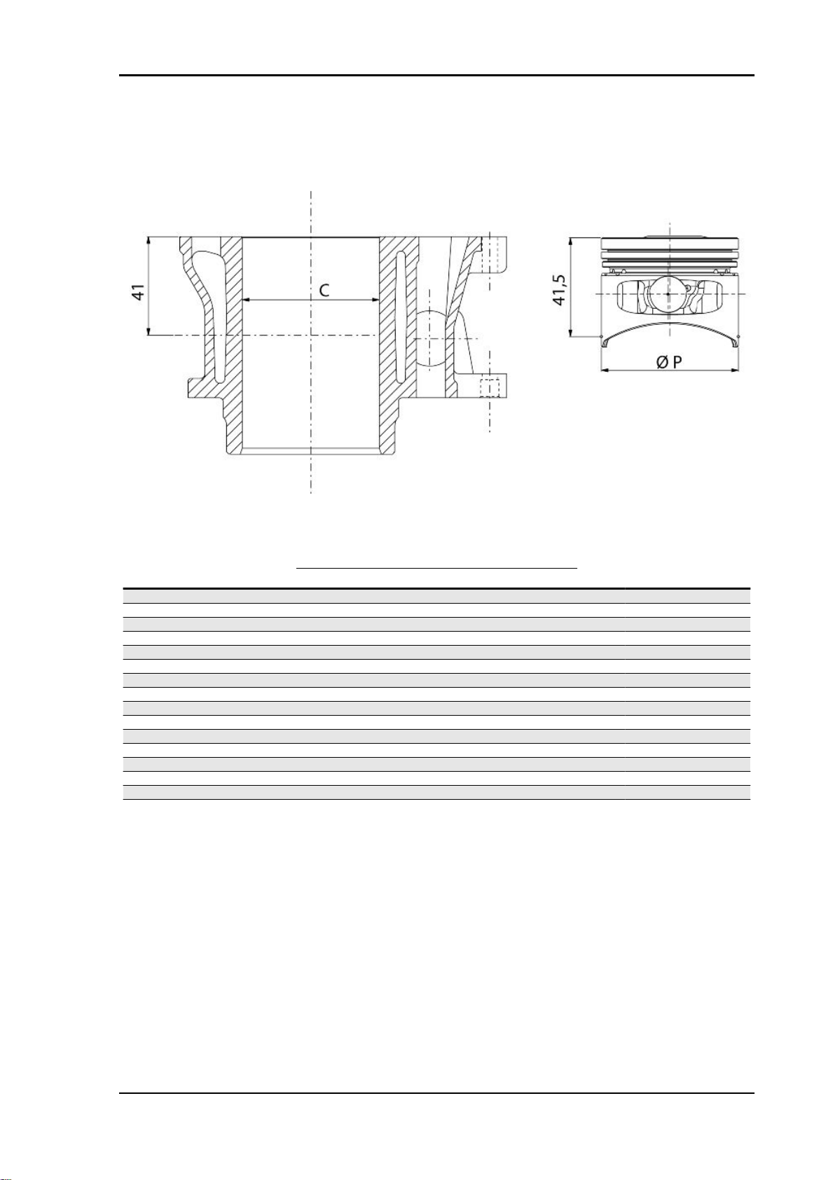
Characteristic
Compression ratio, 200 models
Cr: 11÷12 :1
Measurement "A" to be taken is a value of piston re-entry, it indicates by how much the plane formed
by the piston crown falls below the plane formed by the top of the cylinder. The further the piston falls
inside the cylinder, the less the base gasket to be applied (to recover the compression ratio) and vice
versa.
N.B.
MEASUREMENT "A" MUST BE TAKEN WITHOUT ANY GASKET FITTED BETWEEN THE CRANKCASE AND CYLINDER AND AFTER RESETTING THE GAUGE, EQUIPPED WITH A SUPPORT, ON
A GROUND PLANE
THICKNESS 200
Name
Gasket thickness 200 1,7 ÷ 1,6 0,4 ± 0,05
Gasket thickness 200 1,6 ÷ 1,4 0,6 ± 0,05
Gasket thickness 200 1,4 ÷ 1,3 0,8 ± 0,05
Measure A Thickness
CHAR - 18
Page 19
Vespa GT 125-200 Characteristics
Oversizes
ENGINE 125 OVERSIZE
Name
Compression ring 57 x 1 A 0.15 ÷ 0.30
Oil scraper ring 57 x 1 A 0.10 ÷ 0.30
Oil scraper ring 57 x 2.5 A 0.15 ÷ 0.35
Compression ring 1st
oversize
Oil scraper ring 1st
Oversize
Oil scraper ring 1st
Oversize
Compression ring 2nd
Oversize
Oil scraper ring 2nd
Oversize
Oil scraper ring 2nd
Oversize
Compression ring 3rd
Oversize
Oil scraper ring 3rd
Oversize
Oil scraper ring 3rd
Oversize
Description Dimensions Initials Quantity
57.2 x 1 A 0.15 ÷ 0.30
57.2 x 1 A 0.10 ÷ 0.30
57.2 x 2.5 A 0.15 ÷ 0.35
57.4 x 1 A 0.15 ÷ 0.30
57.4 x 1 A 0.10 ÷ 0.30
57.4 x 2.5 A 0.15 ÷ 0.35
57.6 x 1 A 0.15 ÷ 0.30
57.6 x 1 A
57.6 x 2.5 A 0.15 ÷ 0.35
ENGINE 200 OVERSIZE
Name
Oil scraper ring 72 x 2.5 A 0.20 ÷ 0.40
Oil scraper ring 72 x 1 A 0.20 ÷ 0.40
Compression ring 72 x 1.5 A 0.15 ÷ 0.30
Description Dimensions Initials Quantity
CHAR - 19
Page 20

Characteristics Vespa GT 125-200
Products
RECOMMENDED PRODUCTS
Product Description Specifications
AGIP ROTRA 80W-90 Rear hub oil SAE 80W/90 Oil that exceeds the re-
AGIP FILTER OIL Oil for air filter sponge Mineral oil with specific additives for in-
AGIP GP 330 Calcium complex soap-based grease
AGIP CITY HI TEC 4T Four-stroke engine oil Lubricating oil for flexible shafts (throttle
AGIP BRAKE 4 Brake fluid FMVSS DOT 4 Synthetic fluid
AGIP PERMANENT PLUS Coolant Monoethylene glycol antifreeze fluid, CU-
MONTBLANC MOLYBDENUM
GREASE
AGIP GREASE PV2 Grease for the steering bearings, pin
with NLGI 2; ISO-L-XBCIB2
Grease for driven pulley shaft adjusting
ring and movable driven pulley housing
seats and swinging arm
quirements of API GL3 specifications
creased adhesiveness
Grease (brake control levers, throttle
grip)
control)
NA NC 956-16
Grease with molybdenum disulphide
White anhydrous-calcium based grease
to protect roller bearings; temperature
range between -20 C and +120 C; NLGI
2; ISO-L-XBCIB2.
CHAR - 20
Page 21

INDEX OF TOPICS
TOOLING TOOL
Page 22
Tooling Vespa GT 125-200
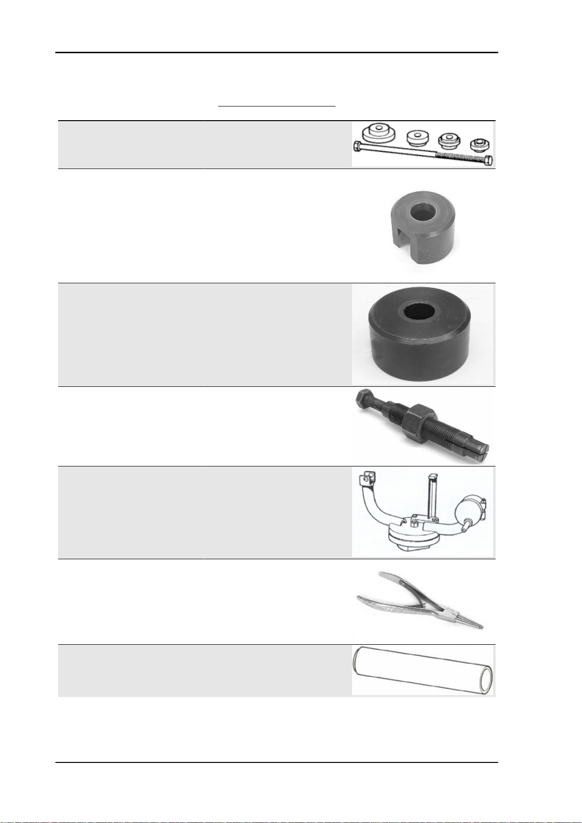
APPROPRIATE TOOLS
Stores code Description
001330Y Tool for fitting steering seats
001467Y009 Driver for OD 42-mm bearings
001467Y017 Bell for bearings, OD 39 mm
001467Y014 Pliers to extract ø 15-mm bearings
005095Y Engine support
002465Y Pliers for circlips
006029Y Punch for fitting fifth wheel seat on steer-
ing tube
TOOL - 22
Page 23
Vespa GT 125-200 Tooling
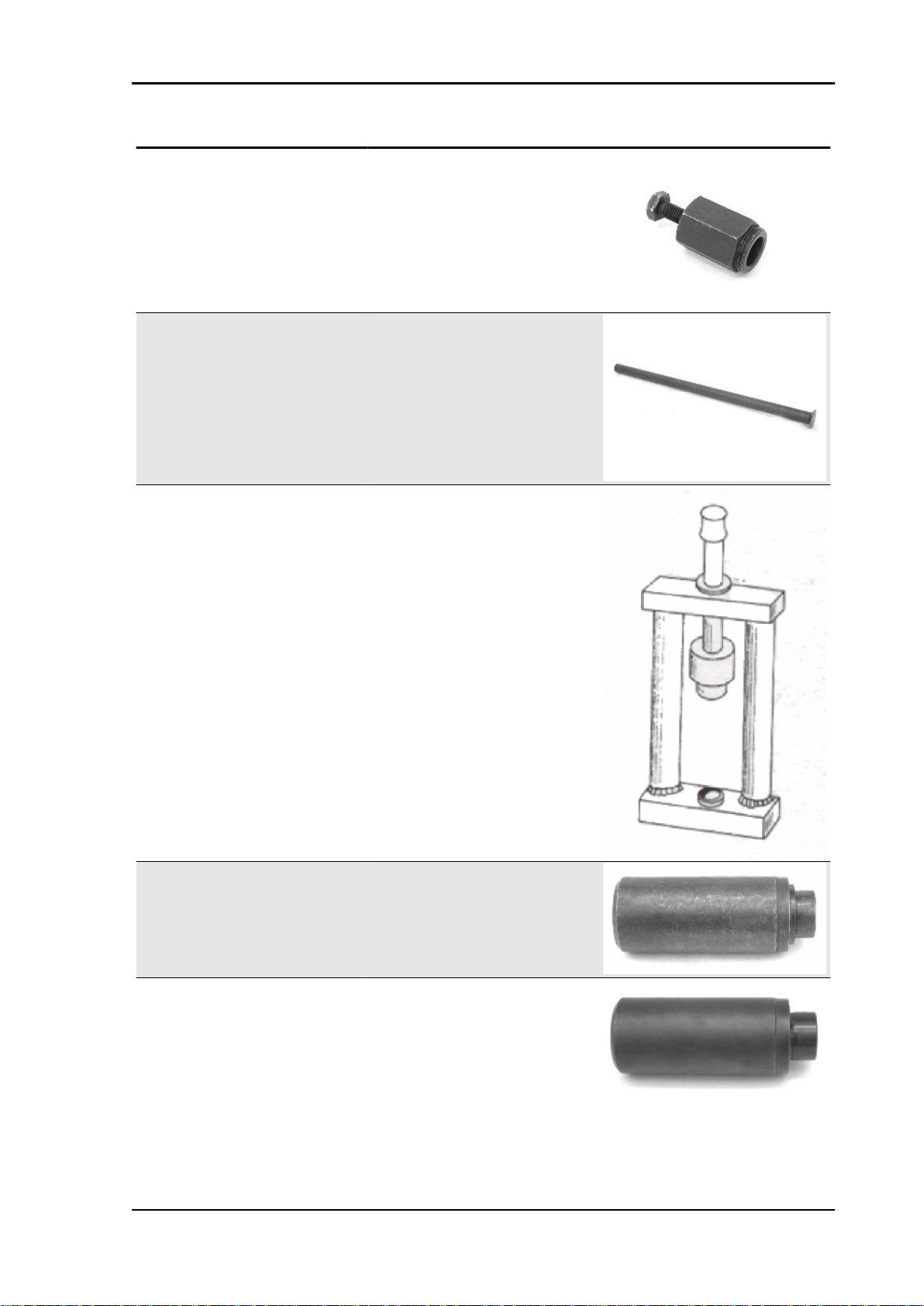
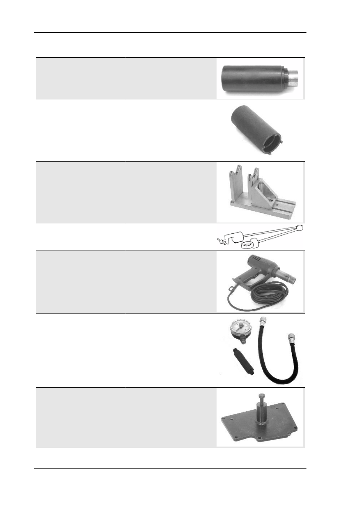
Stores code Description
008564Y Flywheel extractor
020004Y Punch for removing fifth wheels from
020021Y Front suspension service tool
headstock
020036Y Punch
020037Y Punch
TOOL - 23
Page 24
Tooling Vespa GT 125-200
Stores code Description
020038Y Punch
020055Y Wrench for steering tube ring nut
020074Y Support base for checking crankshaft
020150Y Air heater support
020151Y Air heater
020193Y Oil pressure gauge
alignment
TOOL - 24
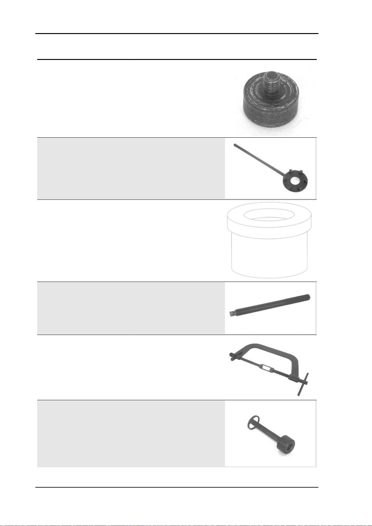
020262Y Crankcase splitting strip
Page 25
Vespa GT 125-200 Tooling
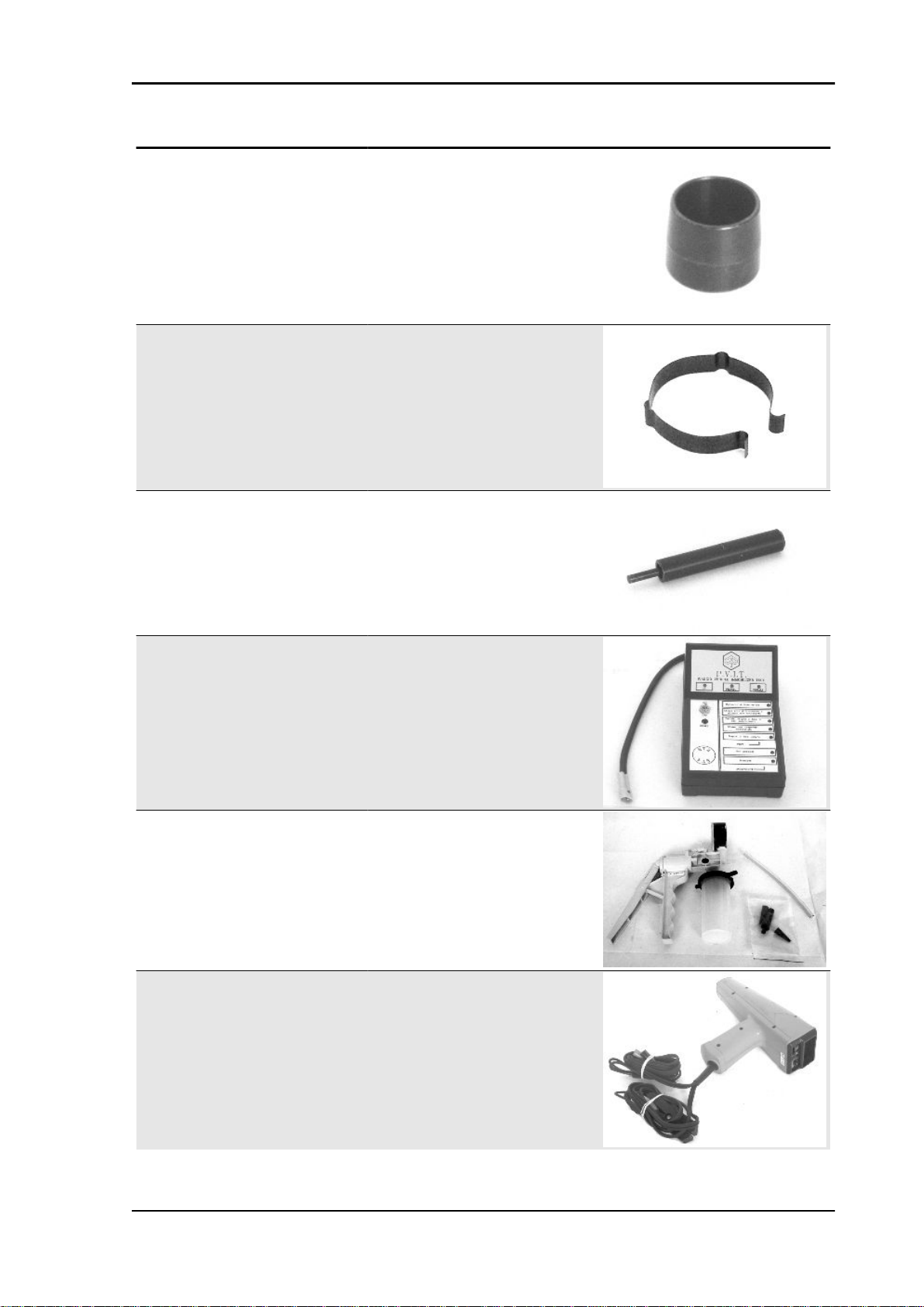
Stores code Description
020263Y Sheath for driven pulley fitting
020287Y Clamp to assemble piston on cylinder
020306Y Punch for assembling valve seal rings
020319Y Immobilizer check tester
020329Y MityVac vacuum-operated pump
020330Y Stroboscopic light to check timing
TOOL - 25
Page 26
Tooling Vespa GT 125-200
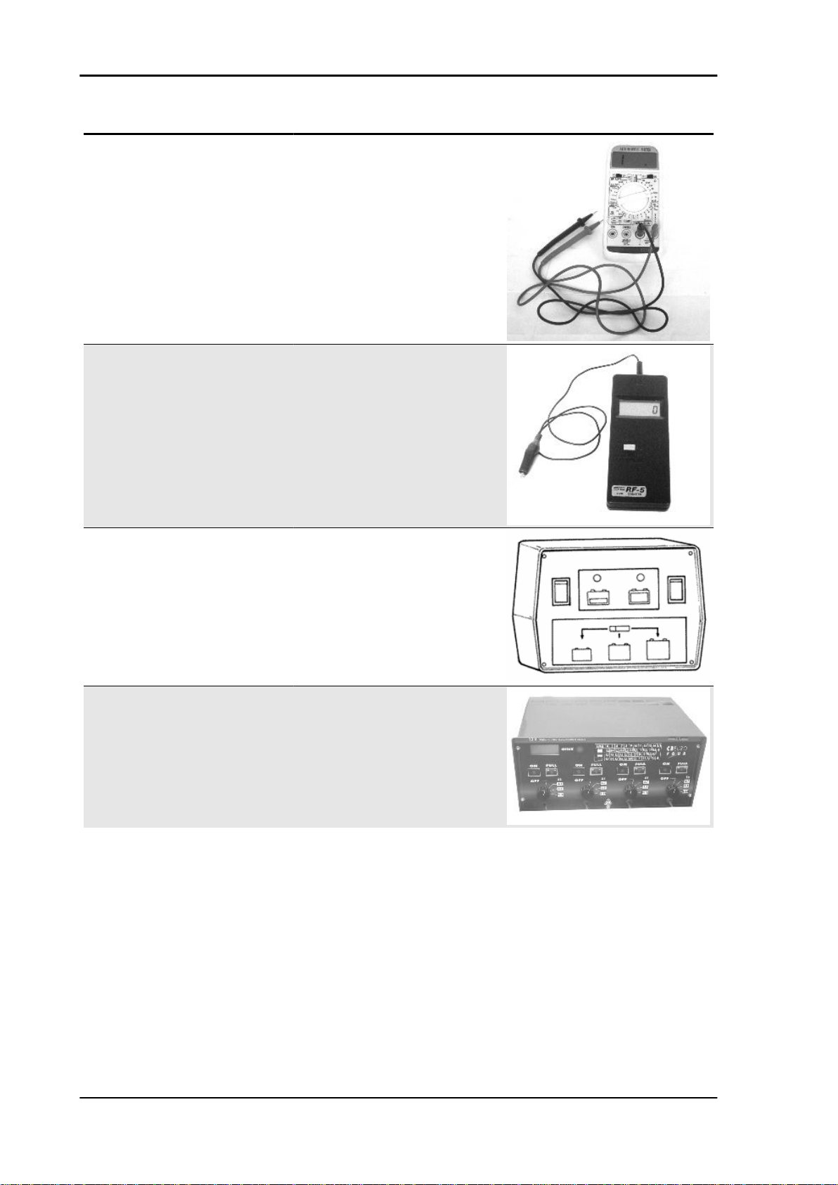
Stores code Description
020331Y Digital multimeter
020332Y Digital rev counter
020333Y Single battery charger
020334Y Multiple battery charger
TOOL - 26
Page 27
Vespa GT 125-200 Tooling
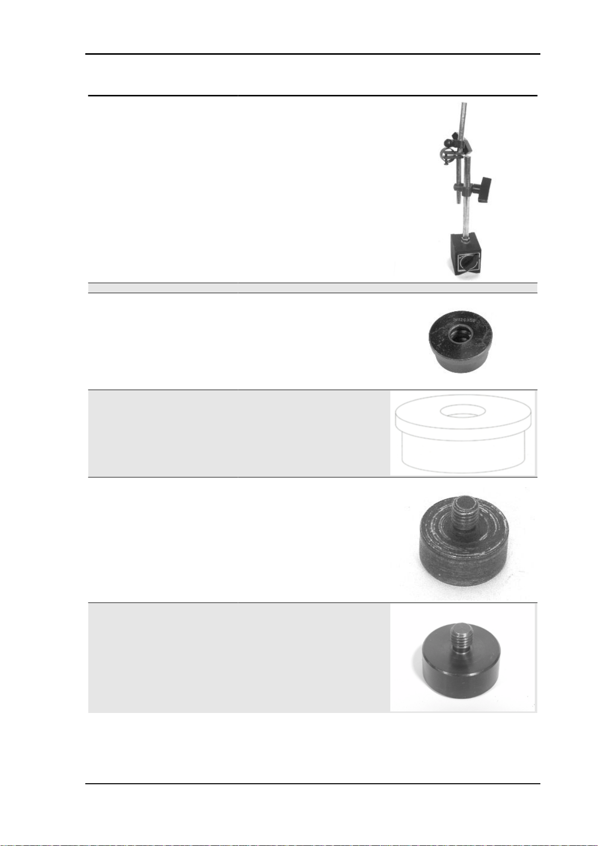
Stores code Description
020335Y Magnetic support for dial gauge
020357Y 32 x 35 mm adaptor
020359Y 42x47-mm adaptor
020360Y Adaptor 52 x 55 mm
020363Y 20 mm guide
020364Y 25-mm guide
TOOL - 27
Page 28
Tooling Vespa GT 125-200
Stores code Description
020365Y 22 mm guide
020368Y driving pulley lock wrench
020375Y Adaptor 28 x 30 mm
020376Y Adaptor handle
020382Y Valve cotters equipped with part 012 re-
020382Y011 adapter for valve removal tool
moval tool
TOOL - 28
Page 29
Vespa GT 125-200 Tooling
Stores code Description
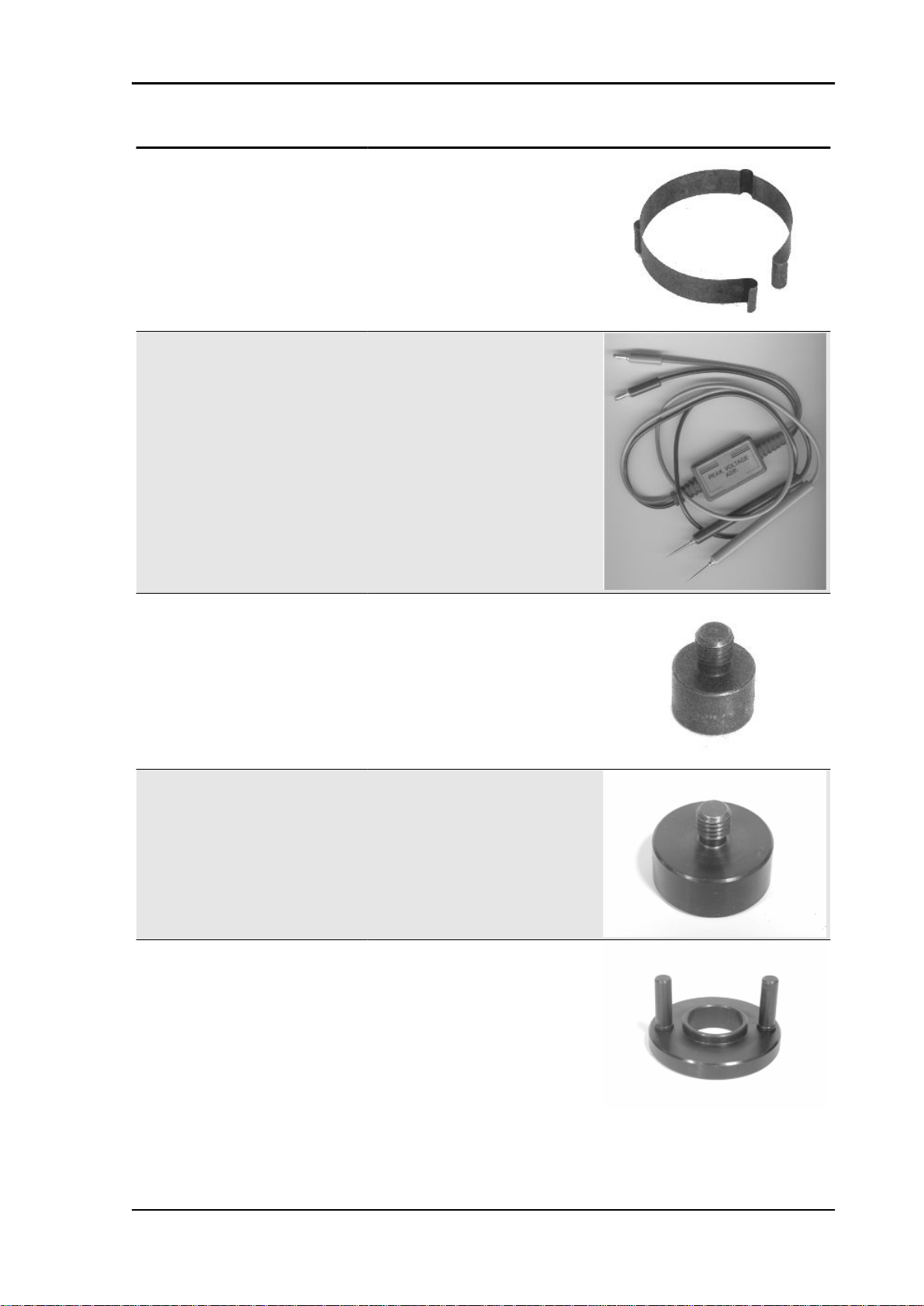
020393Y Piston fitting band
020409Y Multimeter adaptor - Peak voltage detec-
020412Y 15 mm guide
020414Y 28-mm guide
tion
020423Y driven pulley lock wrench
TOOL - 29
Page 30
Tooling Vespa GT 125-200
Stores code Description
020424Y Driven pulley roller casing fitting punch
020425Y Punch for flywheel-side oil seal
020426Y Piston fitting fork
020430Y Pin lock fitting tool
020431Y Valve oil seal extractor
020434Y Oil pressure control fitting
TOOL - 30
Page 31

Vespa GT 125-200 Tooling
Stores code Description
020439Y 17 mm guide
020440Y Water pump service tool
020441Y 26 x 28 mm adaptor
020442Y Pulley lock wrench
020444Y Tool for fitting/ removing the driven pulley
clutch
TOOL - 31
Page 32

Tooling Vespa GT 125-200
Stores code Description
020455Y 10-mm guide
020456Y Ø 24 mm adaptor
020477Y Adaptor 37 mm
020483Y 30 mm guide
020488Y Pin stops fitting tool (200 cm³ engines)
020489Y Hub cover support stud bolt set
TOOL - 32
Page 33

Vespa GT 125-200 Tooling
Stores code Description
020565Y Flywheel lock calliper spanner
494929Y Exhaust fumes analyser
TOOL - 33
Page 34

INDEX OF TOPICS
MAINTENANCE MAIN
Page 35

Vespa GT 125-200 Maintenance
Maintenance chart
EVERY 2 YEARS
Action
Secondary air filter (external / internal) - Clean
Coolant - change
Brake fluid - change
EVERY 3,000 KM
10'
Action
Engine oil - level check/ top-up
AT 1000 KM OR 4 MONTHS
70'
Action
Hub oil level - Check / Replace
Idle speed (*) - adjustment
Throttle lever - adjustment
Steering - adjustment
Brake control levers - greasing
Brake pads - check condition and wear
Brake fluid level - check
Safety locks - check
Electrical system and battery - check
Vehicle and brake test - road test
Safety locks: see Before delivery chapter.
(*) See rules
AT 6000 KM OR 12 MONTHS
130'
Engine oil - replacement
Hub oil level - Check / Replace
Spark plug / electrode gap - check / replacement
Air filter - cleaning
Engine oil - change
Valve clearance - check
Valve clearance 200 - check
Variable speed rollers - check or replacement
Driving belt - Check / Replacement
Coolant level - check
Brake pads - check condition and wear
Brake fluid level - check
Electrical system and battery - check
Tyre pressure and wear - check
Vehicle and brake test - road test
AT 12000 KM OR 24 MONTHS AND AT 60000 KM
135'
Engine oil - replacement
Hub oil level - Check / Replace
Spark plug / electrode gap - check / replacement
Air filter - cleaning
Engine oil - change
Idle speed (*) - adjustment
Throttle lever - adjustment
Variable speed rollers - check or replacement
Action
Action
MAIN - 35
Page 36

Maintenance Vespa GT 125-200
Action
Driving belt - Check / Replacement
Coolant level - check
Steering - adjustment
Brake control levers - greasing
Brake pads - check condition and wear
Brake fluid level - check
Transmission elements - lubrication
Safety locks - check
Suspensions - check
Electrical system and battery - check
Headlight - adjustment check
Tyre pressure and wear - check
Vehicle and brake test - road test
Safety locks: see Before delivery chapter.
(*) See rules
AT 18000 KM AND AT 54000 KM (125)
100'
Action
Engine oil - replacement
Hub oil level - Check / Replace
Spark plug / electrode gap - check / replacement
Air filter - cleaning
Engine oil - change
Variable speed rollers - check or replacement
Driving belt - Check / Replacement
Coolant level - check
Radiator - external cleaning/ check
Brake pads - check condition and wear
Brake fluid level - check
Electrical system and battery - check
Tyre pressure and wear - check
Vehicle and brake test - road test
AT 18000 KM AND AT 54000 KM (200)
140'
Engine oil - replacement
Hub oil level - Check / Replace
Spark plug / electrode gap - check / replacement
Air filter - cleaning
Engine oil - change
Valve play 200 - recording
Variable speed rollers - check or replacement
Driving belt - Check / Replacement
Coolant level - check
Radiator - external cleaning/ check
Brake pads - check condition and wear
Brake fluid level - check
Electrical system and battery - check
Tyre pressure and wear - check
Vehicle and brake test - road test
AT 24000 KM AND AT 48000 KM (125)
190'
Engine oil - replacement
Hub oil level - Check / Replace
Spark plug / electrode gap - check / replacement
Air filter - cleaning
Engine oil - change
Valve clearance - check
Idle speed (*) - adjustment
Action
Action
MAIN - 36
Page 37

Vespa GT 125-200 Maintenance
Action
Throttle lever - adjustment
Variable speed rollers - check or replacement
Driving belt - Check / Replacement
Coolant level - check
Steering - adjustment
Brake control levers - greasing
Brake pads - check condition and wear
Brake fluid level - check
Transmission elements - lubrication
Safety locks - check
Suspensions - check
Electrical system and battery - check
Headlight - adjustment check
Tyre pressure and wear - check
Vehicle and brake test - road test
Safety locks: see Before delivery chapter.
(*) See rules
AT 24000 KM AND AT 48000 KM (200)
150'
Action
Engine oil - replacement
Hub oil level - Check / Replace
Spark plug / electrode gap - check / replacement
Air filter - cleaning
Engine oil - change
Valve clearance - check
Idle speed (*) - adjustment
Throttle lever - adjustment
Variable speed rollers - check or replacement
Driving belt - Check / Replacement
Coolant level - check
Steering - adjustment
Brake control levers - greasing
Brake pads - check condition and wear
Brake fluid level - check
Transmission elements - lubrication
Safety locks - check
Suspensions - check
Electrical system and battery - check
Headlight - adjustment check
Tyre pressure and wear - check
Vehicle and brake test - road test
Safety locks: see Before delivery chapter.
(*) See rules
AT 30000 KM AT 42000 KM AND AT 66000 KM
90'
Engine oil - replacement
Hub oil level - Check / Replace
Spark plug / electrode gap - check / replacement
Air filter - cleaning
Engine oil - change
Variable speed rollers - check or replacement
Driving belt - Check / Replacement
Coolant level - check
Brake pads - check condition and wear
Brake fluid level - check
Electrical system and battery - check
Tyre pressure and wear - check
Vehicle and brake test - road test
Action
MAIN - 37
Page 38

Maintenance Vespa GT 125-200
AT 36000 KM (125)
205'
Action
Engine oil - replacement
Hub oil level - Check / Replace
Spark plug / electrode gap - check / replacement
Air filter - cleaning
Engine oil - change
Valve clearance - adjustment
Idle speed (*) - adjustment
Throttle lever - adjustment
Variable speed rollers - check or replacement
Driving belt - Check / Replacement
Coolant level - check
Radiator - external cleaning/ check
Steering - adjustment
Brake control levers - greasing
Brake pads - check condition and wear
Brake fluid hoses - replacement
Brake fluid level - check
Transmission elements - lubrication
Safety locks - check
Suspensions - check
Electrical system and battery - check
Headlight - adjustment check
Tyre pressure and wear - check
Vehicle and brake test - road test
Safety locks: see Before delivery chapter.
(*) See rules
245'
Engine oil - replacement
Hub oil level - Check / Replace
Spark plug / electrode gap - check / replacement
Air filter - cleaning
Engine oil - change
Valve play 200 - recording
Idle speed (*) - adjustment
Throttle lever - adjustment
Variable speed rollers - check or replacement
Driving belt - Check / Replacement
Coolant level - check
Radiator - external cleaning/ check
Steering - adjustment
Brake control levers - greasing
Brake pads - check condition and wear
Brake fluid hoses - replacement
Brake fluid level - check
Transmission elements - lubrication
Safety locks - check
Suspensions - check
Electrical system and battery - check
Headlight - adjustment check
Tyre pressure and wear - check
Vehicle and brake test - road test
Safety locks: see Before delivery chapter.
(*) See rules
AT 36000 KM (200)
Action
260'
MAIN - 38
AT 72000 KM
Page 39

Vespa GT 125-200 Maintenance
Action
Engine oil - replacement
Hub oil level - Check / Replace
Spark plug / electrode gap - check / replacement
Air filter - cleaning
Engine oil - change
Valve clearance - check
Valve play 200 - recording
Idle speed (*) - adjustment
Throttle lever - adjustment
Variable speed rollers - check or replacement
Driving belt - Check / Replacement
Coolant level - check
Radiator - external cleaning/ check
Steering - adjustment
Brake control levers - greasing
Brake pads - check condition and wear
Brake fluid hoses - replacement
Brake fluid level - check
Transmission elements - lubrication
Safety locks - check
Electrical system and battery - check
Headlight - adjustment check
Tyre pressure and wear - check
Vehicle and brake test - road test
Safety locks: see Before delivery chapter.
(*) See rules
Carburettor
- Disassemble the carburettor in its parts, wash all
of them with solvent, dry all body grooves with
compressed air to ensure adequate cleaning.
- Check carefully that the parts are in good condition.
- The throttle valve should move freely in the
chamber. Replace it in case of excessive clearance due to wear.
- If there are wear marks in the chamber causing
inadequate tightness or a free valve slide (even if
it is new), replace the carburettor.
- It is advisable to replace the gaskets at every refit
WARNING
PETROL IS HIGHLY EXPLOSIVE ALWAYS REPLACE THE
GASKETS TO AVOID PETROL LEAKS
1. Diaphragm cover
MAIN - 39
Page 40

Maintenance Vespa GT 125-200
2. Gas valve spring
3. Tapered pin support
4. Tapered pin spring
5. Tapered pin
6. Throttle valve diaphragm
7. Automatic starter
8. Idle speed adjustment screw
9. Accelerating pump rocking lever
10.Idle mixture adjustment screw
11.Float pin
12.Acceleration pump unit
13.Float
14.Tank
15.Minimum jet
16.Maximum jet
17.Diffuser
18.Tank drainage screw.
Checking the spark advance
- To check ignition advance, use the stroboscopic
light with induction pincers connected to the spark
plug power wire.
- Connect the induction pincers being careful to
respect the proper polarity (the arrow stamped on
the pincers must be pointing at the spark plug).
- Place the light selector in central position (1 spark
= 1 crankshaft revolution as in 2 T engines).
- Start the engine and check that the light works
properly and the rpm indicator can read also the
high rpm (e.g. 8000 rpm).
- If flash unsteadiness or revolution reading error
is detected (e.g. half values), increase the resistive
load on the spark plug power line (10 ÷ 15 KΩ in
series to AT cable).
- Remove the plastic cover from the slot on the flywheel cover.
MAIN - 40
Page 41

Vespa GT 125-200 Maintenance
- Operating on the flash corrector displacement of
the bulb, make the reference on the flywheel cover
coincide with level on the water pump drive. Read
the advance degrees indicated by the stroboscopic light.
- Check that the advance degrees corresponds
with the rotation rpm as indicated in the table.
- If there are anomalies, check the Pick-Up and the
control unit power supply (positive-negative), replace the control unit if necessary.
- The brand new control unit prevents that the engine rotation exceeds 2000 rpm.
- The programmed control unit allows the engine
to rotate within the prescribed limits.
Characteristic
Check ignition advance 125
10° ± 1° at 2000 rpm - 34° ± 1° at 6000 rpm
variable ignition advance (before T.D.C.) 200
10°±1 at 2000 rpm - 32°±1 at 6500 rpm
Spark advance variation
Specification
Spark elimination First threshold : 1 spark on 7 Second threshold : 2 sparks on 3
Version 200 : Operation threshold First threshold : 9900 ±50 Second threshold : 10100 ±50
Version 200 : Reactivation threshold First threshold : 9800 ±50 Second threshold: 10000 ±50
VERSION 200
Desc./Quantity
MAIN - 41
Page 42

Maintenance Vespa GT 125-200
MAIN - 42
VERSION 125
Specification
Operation threshold First threshold : 10700 ±50
Reactivation threshold First threshold : 10600±50
Spark elimination First threshold : 1 spark on 7
Second threshold : 2 sparks on 3
Desc./Quantity
Second threshold : 11000 ±50
Second threshold : 10900±50
Page 43

Vespa GT 125-200 Maintenance
Spark plug
- Rest the vehicle on the central stand.
-Open the saddle and extract the helmet compartment
- Disconnect the spark plug H.V. cable cap.
- Unscrew the spark plug, using the spanners supplied.
- Inspect the spark plug, the insulator's integrity,
too worn or sooty electrodes, sealing washer state,
and measure the distance between the electrodes
using the special thickness gauge.
MAIN - 43
Page 44

Maintenance Vespa GT 125-200
- Adjust the distance, if required, by bending the
side electrode carefully. In case of irregularity, replace the spark plug with one of the recommended
type.
- Insert the spark plug with the proper inclination,
and screw it thoroughly by hand, then tighten it
using the special wrench.
- Insert the cap over the spark plug thoroughly and
proceed to re-assembly
CAUTION
THE SPARK PLUG MUST BE REMOVED WHEN THE MO-
TOR IS COLD. THE SPARK PLUG MUST BE REPLACED
EVERY 12,000 KM. THE USE OF NON CONFORMING IGNITION CONTROL UNITS OR SPARK PLUGS OTHER THAN
THOSE PRESCRIBED CAN SERIOUSLY DAMAGE THE ENGINE.
Characteristic
Spark plug 125
Champion RG 4 HC
Spark plug 200
CHAMPION RG 6 YC
Electrode gap
0.7-0.8 mm
Locking torques (N*m)
Spark plug 12 ÷ 14
Hub oil
Check
-Stand the vehicle on its centre stand on flat
ground;
-Remove the oil dipstick "A", dry it with a clean
cloth and put it back into its hole tightening it
completely;
-Take out the dipstick checking that the oil level
reaches the dipstick lower notch; if the level is under the MAX. mark, it needs to be filled with the
right amount of hub oil.
-Screw up the oil dipstick again and make sure it
is locked properly into place.
MAIN - 44
Page 45

Vespa GT 125-200 Maintenance
Replacement
-Remove the oil cap «A».
- Unscrew the oil drainage cap "B" and drain out
all the oil.
- Screw in the drainage cap again and fill the hub
with the prescribed oil.
Recommended products
AGIP ROTRA 80W-90 Rear hub oil
SAE 80W/90 Oil that exceeds the requirements of
API GL3 specifications
Characteristic
Rear hub oil
Capacity ~ 150 cm³
Locking torques (N*m)
Hub oil drainage screw 15 ÷ 17 Nm
Air filter
Cleaning (Every 12,000 km):
- Wash with water and car shampoo.
- Dry with short blasts of compressed air and a clean cloth.
- Soak with a 50% mixture of gasoline and oil.
- Drip dry the filtering element and then squeeze it with your hands without wringing.
- Refit the filtering element.
CAUTION
NEVER RUN THE ENGINE WITHOUT THE AIR FILTER, THIS WILL RESULT IN AN EXCESSIVE
CYLINDER AND PISTON WEAR AND ALSO IN CARBURETTOR DAMAGE.
CAUTION
WHEN TRAVELLING ON DUSTY ROADS, THE AIR FILTER MUST BE CLEANED MORE OFTEN
THAN SHOWN IN THE SCHEDULED MAINTENANCE CHART.
Recommended products
MAIN - 45
Page 46

Maintenance Vespa GT 125-200
AGIP FILTER OIL Oil for air filter sponge
Mineral oil with specific additives for increased adhesiveness
- Remove the left side panel.
- Remove the air cleaner cover after unscrewing
the 9 fixing screws.
- Take out the filtering element.
- Replace the air filter with a new one.
N.B.
EVERY 6,000 KM CHECK THE AIR FILTER AND IF RE-
QUIRED, CLEAN IT WITH COMPRESSED AIR. THE AIR JET
MUST BE DIRECTED FROM THE INSIDE TO THE OUTSIDE
OF THE FILTER (I.E. OPPOSITE TO THE SENSE THE AIR
FLOWS AT REGULAR ENGINE RUNNING). EVERY 6,000
KM, UPON SERVICING, REMOVE THE RETAINER AND
RUBBER COVER UNDER THE FILTER HOUSING AS
SHOWN IN THE FIGURE AND DRAIN ALL POSSIBLE OIL
DEPOSITS.
MAIN - 46
Page 47

Vespa GT 125-200 Maintenance
Engine oil
In 4T engines, the engine oil is used to lubricate the distribution elements, the bench bearings and the
thermal group. An insufficient quantity of oil can cause serious damage to the engine.
In all 4T engines, the deterioration of the oil characteristics, or a certain consumption should be considered normal, especially if during the run-in period. Consumption levels in particular can be influenced
by the conditions of use (e.g.: oil consumption increases when driving at "full throttle".
Replacement
Replace oil and filter every 6,000 km. The engine
must be drained by running off the oil from drainage cap "B" of the flywheel side mesh pre-filter;
furthermore to facilitate oil drainage, loosen the
cap/dipstick "A". Once all the oil has drained
through the drainage hole, unscrew the oil cartridge filter "C" and remove it.
Make sure the pre-filter and discharge tap O-rings
are in good condition.
MAIN - 47
Page 48

Maintenance Vespa GT 125-200
Lubricate them and refit the gauze filter and oil
drainage tap, screwing them up to the specified
torque.
Refit the new cartridge filter being careful to lubricate the O-ring before fitting it.
Change the engine oil.
Since a certain quantity of oil still remains in the
circuit, oil must be filled from cap "A". Then start
up the scooter, leave it running for a few minutes
and switch it off: after five minutes check the level
and if necessary top up without exceeding the
MAX level. The cartridge filter must be replaced
every time the oil is changed. Use new oil of the
recommended type for topping up and changing
purposes.
N.B.
THE ENGINE MUST BE HOT WHEN THE OIL IS CHANGED.
Recommended products
AGIP CITY HI TEC 4T Engine oil
SAE 5W-40 Synthetic oil that exceed the requirements of API SL, ACEA A3, JASO MA specifications
Characteristic
Engine oil top-up
600 ÷ 650 cc
Check
This operation must be carried out with the engine cold and following the procedure below:
1. Place the vehicle on its centre stand and on flat ground.
2. Undo cap/dipstick "A", dry it off with a clean cloth and replace it, screwing down completely.
3. Remove the cap/dipstick again and check that the level is between the min and max. marks; top
up if necessary.
The MAX level mark indicates a quantity of around 1100 cc of oil in the engine. If the check is carried
out after the vehicle has been used, and therefore with a hot engine, the level line will be lower; in order
to carry out a correct check it is necessary to wait at least 10 minutes after the engine has been stopped,
so as to get the correct level.
MAIN - 48
Page 49

Vespa GT 125-200 Maintenance
Oil top up
The oil should be topped up after having checked
the level and in any case by adding oil without
ever exceeding the MAX. level.
The restoration level between the MIN and MAX
levels implies a quantity of oil of approx. 400 cc.
Oil pressure warning light
The vehicle is equipped with a warning light on the instrument panel that lights up when the key is turned
to the «ON» position. However, this light should switch off once the engine has been started.
If the light turns on during braking, at idling speed or while turning a corner, it is necessary to
check the oil level and the lubrication system.
Checking the ignition timing
-Remove the 4 fixing screws and move away from
the engine the flywheel cover fitted with a water
pump and cooling manifolds.
-Rotate the flywheel until the reference matches
the crankcase operation end as shown in the figure
(TDC). Make sure that the 4V reference point on
the camshaft control pulley is aligned with the reference point on the head as shown in the second
figure. If the reference mark is opposite the indicator on the head, make the crankshaft turn once
more.
-The TDC reference mark is repeated also between the flywheel cooling fan and the flywheel
cover.
To use this reference mark, remove the spark plug
and turn the engine in the opposite direction to the
normal direction using a calliper spanner applied
to the camshaft command pulley casing.
N.B.
TIME THE TIMING SYSTEM UNIT IF IT IS NOT IN PHASE.
MAIN - 49
Page 50

Maintenance Vespa GT 125-200
Cooling system
Introduction of the engine coolant.
The fluid level inspection should be carried out every 6,000 km when the motor is cold, following the
methods indicated below:
Place the scooter on its centre stand and on flat
ground.
- Undo the screw shown in the figure and remove
the expansion tank cap on RHS.
- Top up if the fluid level is near or below the MIN
level edge. The liquid level must always be between the MIN and MAX level.
-The coolant consists of an ethylene glycol and
corrosion inhibitor based 50% de-ionised waterantifreeze solution mix.
CAUTION
DO NOT EXCEED THE MAX. LEVEL WHEN FILLING SO AS
TO AVOID THE COOLANT ESCAPING FROM THE EXPANSION TANK WHEN THE vehicle IS IN USE.
Braking system
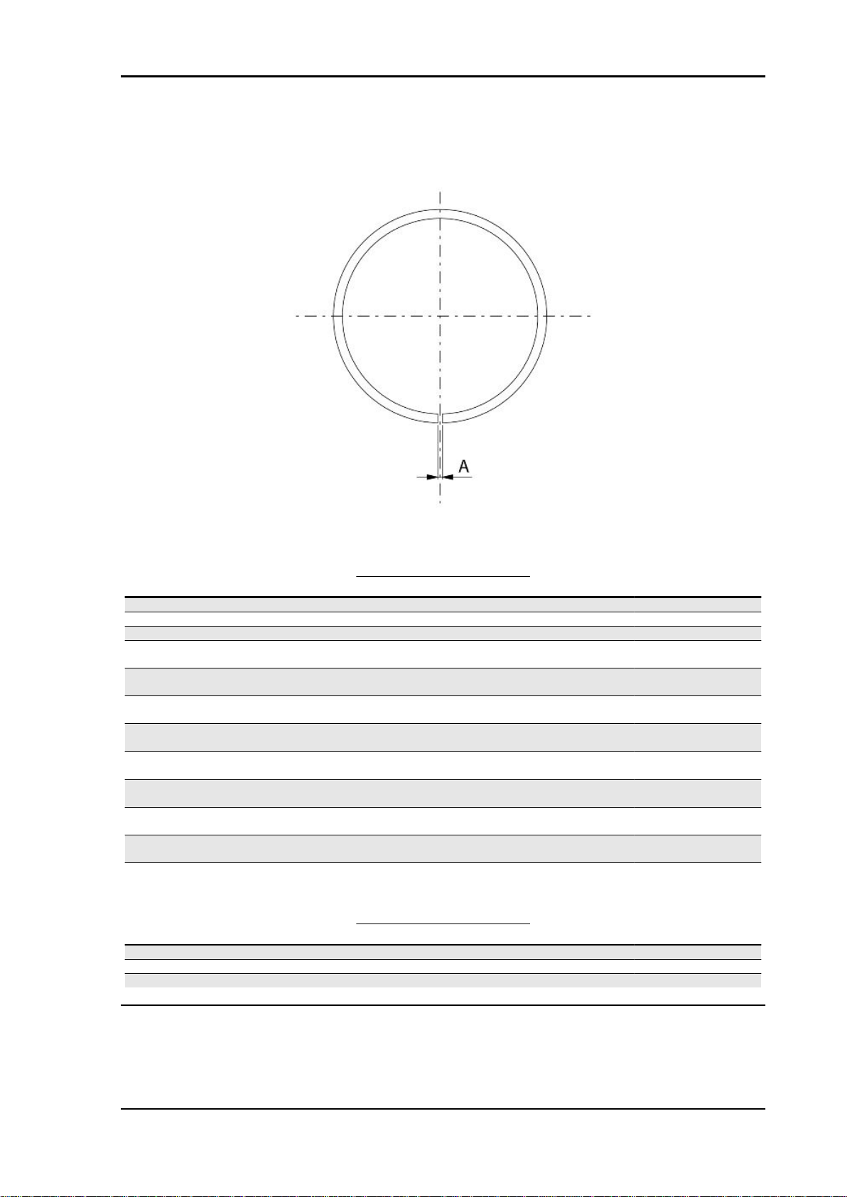
Level check
The brake fluid tanks for the front and rear brakes
are located on the pumps under the handlebar
cover. Proceed as follows:
- Remove the brake pump cover
- Rest the vehicle on its centre stand with the handlebars perfectly horizontal;
- Check the fluid level through the sight glass as
shown in the figure. A certain lowering of the level
is caused by wear on the pads.
MAIN - 50
Page 51

Vespa GT 125-200 Maintenance
Top-up
- Position the vehicle on a flat surface and on the
centre stand
- Remove the brake pump cover as indicated in the
photo
Check the brake fluid level through the sight glass
on the pump as shown in the photograph
- If the level is below the minimum, fill using the two
screws shown in the figure
- Remove the gasket and fill with DOT 4 until the spyglass is completely covered
MAIN - 51
Page 52

Maintenance Vespa GT 125-200
For refitting purposes carry out the operations in
the reverse order from the removal operation and
respect the tightening torque of the tank cover
screws.
CAUTION
AVOID CONTACT OF THE BRAKE FLUID WITH YOUR
EYES, SKIN, AND CLOTHING. IN CASE OF ACCIDENTAL
CONTACT, WASH WITH WATER.
CAUTION
THE BRAKING CIRCUIT FLUID IS HIGHLY CORROSIVE.
THEREFORE, WHEN TOPPING IT UP, AVOID LETTING IT
COME INTO CONTACT WITH THE PAINTED PARTS OF
THE VEHICLE. THE BRAKING CIRCUIT FLUID IS HYGROSCOPIC, THAT IS, IT ABSORBS HUMIDITY FROM THE
SURROUNDING AIR. IF MOISTURE CONTAINED IN THE
BRAKE FLUID EXCEEDS A CERTAIN VALUE, THIS WILL
RESULT IN INEFFICIENT BRAKING.
CAUTION
NEVER USE BRAKE FLUID COMING FROM OPEN OR PAR-
TIALLY USED CONTAINERS. UNDER NORMAL CLIMATIC
CONDITIONS, BRAKE FLUID MUST BE CHANGED EVERY
20,000 KM OR ANYWAY EVERY 2 YEARS.
Locking torques (N*m)
Brake pump reservoir screws 15 ÷ 20
Headlight adjustment
- Position the unloaded vehicle, in running conditions and with the tyres inflated to the prescribed
pressure, onto a flat surface 10 m away from a
white screen in a half-lit room, and make sure the
vehicle longitudinal axis is perpendicular to the
screen.
- Draw a horizontal line on the screen at a height
of 67 ÷ 70 cm from the ground.
- Remove the front radiator grille working on the
screw indicated in the photograph
- Switch on the low-beam headlight and check that
the horizontal borderline between the projected
light beam and the dark area is not higher than the
horizontal line drawn on the screen. To remove the
headlight, act on the screw indicated in the figure.
MAIN - 52
Page 53

Vespa GT 125-200 Maintenance
CO check
Remove the side, then remove the transmission side cooling air inlet so as to easily reach the flow
adjustment screw
- Remove the gas cap on the exhaust pipe.
- Using the original washer, install the exhaust gas
collection Kit union.
- Suitably orientate the components.
- Close the gas outlet terminal of the tool.
- Start the engine and let it warn until the electric
fan starts.
- Stop the engine.
MAIN - 53
Page 54

Maintenance Vespa GT 125-200
- Disconnect the SAS check valve vacuum pipe
from the «T» branch shown in the figure.
- Close the branch using a cap or a pipe portion
with conical cap.
- Connect the Mitivac vacuum pump to the control
pipe and to the SAS valve.
- Start the vacuum up to - 0.6 - 0.8 Bar so as to
close the valve and cut off the SAS system.
Remove the exhaust gas collection Kit closing cap and connect the analyser properly pre-heated.
Check the conditions displayed by the analyser and the engine rpm and adjust the CO value at 3.8 ±
0.7 at 1,650 ± 50 rpm
N.B.
CHECK THAT THE RESULT IS OBTAINED WITH THE GAS VALVE IN THE CLOSEST POSITION.
ALSO CHECK THAT THE CARBURETION ADJUSTMENT IS OBTAINED WITH THE FLOW SCREW
OPEN BY 2 TO 4 TURNS.
IF NOT, CHECK THE FUEL LEVEL ADJUSTMENT IN THE BASIN AND CHECK THE FUEL CIRCUIT.
IN CASE OF UNSTEADY CO, CHECK THE CARBURETTOR CLEANING, THE FEEDING SYSTEM
EFFICIENCY AND THE VACUUM SEALS.
IN CASE OF UNBURNT HYDROCARBONS (HC) > OF 1,000 P.P.M., CHECK THE IGNITION SYSTEM, THE TIMING, THE VALVE CLEARANCE AND THE DRAINAGE VALVE SEAL.
Specific tooling
020329Y MityVac vacuum-operated pump
020332Y Digital rev counter
494929Y Exhaust fumes analyser
MAIN - 54
Page 55

Vespa GT 125-200 Maintenance
SAS filters inspection and cleaning
the SAS for leader engines 125 cm³ - 200 cm³ Euro
2 operates in a similar manner to the SAS for 2T
engines.
The differences are the following:
instead of entering through the muffler as for 2T
engine, the secondary air enters directly in the discharge pipe on the head.
The 2T reed valve has a diaphragm. The unit, indicated by an arrow in the figure, has a cut-off
connected to the depression intake on the inlet
manifold that cuts the air inlet in deceleration, to
avoid explosions in the muffler.
System description:
Air is drawn through the opening "A", goes through
the first filter and is channelled through the opening "B"
Air gets to the second filter "B" through the opening
indicated in the figure.
Now, the filtered air enters the diaphragm device,
and then is channelled to the head.
MAIN - 55
Page 56

Maintenance Vespa GT 125-200
The air passes through a rigid pipe connected to
the head and reaches a discharge joint in order to
supply oxygen to the unburned gases before the
catalytic converter, thus favouring an improved reaction of the catalytic converter.
- Remove the muffler.
- Remove the right-hand side fairing
- Remove the coolant inlet and outlet couplings
from the pump cover. Then, drain the system
- Remove the upper clamp of the SAS valve connection coupling to the drainage as indicated in the
photograph
MAIN - 56
Page 57

Vespa GT 125-200 Maintenance
- Remove the 2 fixing screws, the gasket and the
pipe connecting the SAS valve to the head. Then
remove the pipe.
- Release the electrical cable from the flywheel
cover clamp as indicated in the photograph
- Disconnect the depression pipe from the SAS
valve
MAIN - 57
Page 58

Maintenance Vespa GT 125-200
- Remove the pump support bracket and fuel filter.
- Remove the flywheel cover together with the SAS
valve acting on the 4 hexagonal-head screws as
indicated in the photograph
- Remove the SAS valve two fixing screws and remove the SAS valve together with the O-ring from
the support
- Remove the plastic support together with the
gasket
MAIN - 58
Page 59

Vespa GT 125-200 Maintenance
- Check that the SAS valve plastic support is not
dented or distorted
- Check that the gasket is in good conditions
- Carefully clean the inside and outside filters. Replace them if damaged or abnormally distorted.
- Make sure the coupling connecting the secondary air to the head is not dented, overheated or
distorted. If there is, replace it.
- Check that the metal pipe does not have any
dents
CAUTION
INADEQUATE TIGHTNESS BETWEEN THE SAS VALVE
AND ITS SUPPORT INCREASES NOISE IN THE SAS SYSTEM.
To refit, follow the removal procedure in reverse order being careful to respect the direction of the rubber
coupling connecting the SAS valve and the discharge system
MAIN - 59
Page 60

INDEX OF TOPICS
TROUBLESHOOTING TROUBL
Page 61

Vespa GT 125-200 Troubleshooting
This section makes it possible to find what solutions to apply when troubleshooting.
For each failure, a list of the possible causes and pertaining operations is given.
Engine
Poor performance
POOR PERFORMANCE
Possible Cause Operation
The carburettor is dirty; fuel pump or vacuum valve damaged Remove, wash with solvent and dry with compressed air or re-
Incorrect timing or worn timing system elements Time the system again or replace the worn parts
Muffler obstructed Replace
Air filter blocked or dirty. Dismantle the sponge, wash with water and shampoo, then
soak it in a mixture of 50% petrol and 50% of specific oil (Selenia Air Filter Oil), then hand dry without squeezing, allow to
drip dry and then reassemble.
Automatic starter failure Check: mechanical movement, electric connection and fuel
supply, replace if required.
Oil level exceeds maximum Check for causes and fill to reach the correct level
Lack of compression: parts, cylinder and valves worn Replace the worn parts
Transmission belt worn Replace
Inefficient automatic transmission Check the rollers and the pulley movement, replace the dam-
aged parts and lubricate the driven pulley moveable guide with
Montblanc Molybdenum Grease
Clutch slipping Check the clutch system and/or the bell and replace if neces-
Carburettor nozzles clogged Dismantle, wash with solvent and dry with compressed air
place
sary
Rear wheel spins at idle
REAR WHEEL TURNING WITH IDLE ENGINE
Possible Cause
Idling rpms too high Adjust the engine idle speed and the CO%, if necessary.
Clutch fault Check the springs / clutch masses
Intake coupling cracked or clamps incorrectly tightened Replace the intake coupling and check the clamps are tight-
Operation
ened
Starting difficulties
DIFFICULT STARTING
Possible Cause
Altered fuel characteristics Drain off the fuel no longer up to standard; then, refill
Rpm too low at start-up or engine and start-up system dam-
aged
Incorrect valve sealing or valve adjustment Inspect the head and/or restore the correct clearance
- Engine flooded. Try starting-up with the throttle fully open. If the engine fails to
Automatic starter failure Check: mechanical movement, electric connection and fuel
Air filter blocked or dirty. Dismantle the sponge, wash with water and shampoo, then
Check the starter motor, the system and the torque limiter
start, remove the spark plug, dry it and before refitting, make
the motor turn so as to expel the fuel excess taking care to
connect the cap to the spark plug, and this in turn to the ground.
If the fuel tank is empty, refuel and start up.
soak it in a mixture of 50% petrol and 50% of specific oil (Se-
Operation
supply, replace if required.
TROUBL - 61
Page 62

Troubleshooting Vespa GT 125-200
Possible Cause Operation
lenia Air Filter Oil), then hand dry without squeezing, allow to
Faulty spark plug or incorrect ignition advance Replace the spark plug or check the ignition circuit components
The carburettor is dirty; fuel pump or vacuum valve damaged Remove, wash with solvent and dry with compressed air or re-
Battery flat Check the charge of the battery, if there are any sulphur marks,
replace and use the new battery following the instructions
Intake coupling cracked or clamps incorrectly tightened Replace the intake coupling and check the clamps are tight-
Defective floating valve Check the proper sliding of the float and the functioning of the
Carburettor nozzles clogged Dismantle, wash with solvent and dry with compressed air
drip dry and then reassemble.
place
shown in the chapter
ened
valve
Excessive oil consumption/Exhaust smoke
EXCESSIVE CONSUMPTION
Possible Cause Operation
Wrong valve adjustment Adjust the valve clearance properly
Overheated valves Remove the head and the valves, grind or replace the valves
Misshapen/worn valve seats Replace the head assembly
Worn cylinder, Worn or broken piston rings Replace the piston cylinder assembly or piston rings
Worn or broken piston rings or piston rings that have not been
fitted properly
Oil leaks from the couplings or from the gaskets Check and replace the gaskets or restore the coupling seal
Worn valve oil guard Replace the valve oil guard
Worn valve guides Check and replace the head unit if required
Replace the piston cylinder unit or just the piston rings
Insufficient lubrication pressure
POOR LUBRICATION PRESSURE
Possible Cause
By-Pass remains open Check the By-Pass and replace if required. Carefully clean the
Oil pump with excessive clearance Perform the dimensional checks on the oil pump components
Oil filter too dirty Replace the cartridge filter
Oil level too low Restore the level using the recommended oil type (Selenia HI
Engine tends to cut-off at full throttle
THE MOTOR TENDS TO STOP AT MAXIMUM THROTTLE
Possible Cause
Level in tank too low Restore the level in the tank by bending on the float the thrust-
Tank breather hole obstructed Restore the proper tank aeration
Fuel supply pipes choked or clogged Restore the adequate fuel supply
Maximum nozzle dirty - lean mixture Wash the nozzle with solvent and dry with compressed air
Water in the carburettor Empty the tank through the appropriate bleed nipple.
Incorrect float level Restore the level in the tank by bending on the float the thrust-
Faulty fuel supply Check or replace the fuel pump, and check the vacuum intake
Operation
By-Pass area.
Scooter 4 Tech)
Operation
ing reed of the petrol inlet rod so as to have the float parallel to
the tank level with the carburettor inverted.
ing reed of the petrol inlet rod so as to have the float parallel to
the tank level with the carburettor inverted.
and the pipe sealing
TROUBL - 62
Page 63

Vespa GT 125-200 Troubleshooting
Engine tends to cut-off at idle
THE ENGINE TENDS TO STOP AT IDLE
Possible Cause Operation
Air calibrated holes in carburettor blocked Dismantle, wash with solvent and dry with compressed air
Defective floating valve Check the proper sliding of the float and the functioning of the
Level in chamber too high Restore the level of the float chamber bending on the float the
thrusting reed of the petrol inlet pin so as to have the float par-
allel to the float chamber level, with the carburettor inverted.
The starter remains on Check the electric connection, fuel supply and mechanical
movement. Replace if required.
Air filter blocked or dirty. Dismantle the sponge, wash with water and shampoo, then
soak it in a mixture of 50% petrol and 50% of specific oil (Selenia Air Filter Oil), then hand dry without squeezing, allow to
drip dry and then reassemble.
Incorrect timing Time the system and check the timing system components
Cut off device failure Check that the following parts work properly: valve; diaphragm;
spring; and that the air calibration elements are clean; check if
the sponge filter is clean too
Incorrect idle adjustment Adjust using the rpm indicator
Pressure too low at the end of compression Check the thermal group seals and replace worn components
Faulty spark plug or incorrect ignition advance Replace the spark plug or check the ignition circuit components
The starter remains on Check: electric wiring, circuit not interrupted, mechanical
movement and power supply; replace if necessary
Minimum nozzle dirty Wash the nozzle with solvent and dry with compressed air
valve
High fuel consumption
HIGH CONSUMPTION
Possible Cause
Loose nozzles Check the maximum and minimum nozzles are adequately
Fuel pump failure Check the low-pressure duct sealing
Starter inefficient Check: electric wiring, circuit continuity, mechanical sliding and
Air filter obstructed or dirty. Dismantle the sponge, wash with water and shampoo, then
soak it in a mixture of 50% petrol and 50% of specific oil (Selenia Air Filter Oil), then hand dry without squeezing, allow to
Incorrect float level Restore the level in the tank by bending on the float the thrust-
ing reed of the petrol inlet rod so as to have the float parallel to
the tank level with the carburettor inverted.
Transmission and brakes
Clutch grabbing or performing inadequately
IRREGULAR CLUTCH PERFORMANCE OR SLIPPAGE
Possible Cause
Faulty clutch Check that there is no grease on the masses. Check that the
clutch mass contact surface with the casing is mainly in the
centre with equivalent characteristics on the three masses.
Check that the clutch casing is not scored or worn in an anom-
Operation
fixed in their fittings
power supply
drip dry and then reassemble.
Operation
alous way
TROUBL - 63
Page 64

Troubleshooting Vespa GT 125-200
Insufficient braking
INEFFICIENT BRAKING SYSTEM
Possible Cause Operation
Inefficient braking system Check the pad wear (1.5 min). Check that the brake discs are
Fluid leakage in hydraulic braking system Failing elastic fittings, plunger or brake pump seals, replace
Brake disc slack or distorted Check the brake disc screws are locked; measure the axial shift
not worn, scored or warped. Check the correct level of fluid in
the pumps and change brake fluid if necessary. Check there is
no air in the circuits; if necessary, bleed the air. Check that the
front brake calliper moves in axis with the disc.
of the disc with a dial gauge and with wheel mounted on the
scooter.
Brakes overheating
BRAKES OVERHEATING
Possible Cause Operation
Defective sliding of pistons Check calliper and replace any damaged part.
Brake disc slack or distorted Check the brake disc screws are locked; use a dial gauge and
Clogged compensation holes on the pump Clean carefully and blast with compressed air
Swollen or stuck rubber gaskets Replace gaskets.
a wheel mounted on the vehicle to measure the axial shift of
the disc.
Electrical system
Battery
Possible Cause
Battery This is the device in the system that requires the most frequent
Turn signal lights malfunction
TURN INDICATOR NOT WORKING
Possible Cause
Electronic ignition device failure With the key switch set to "ON" jump the contacts 1 (Blue -
BATTERY
Operation
attention and the most thorough maintenance. If the vehicle is
not used for some time (1 month or more) the battery needs to
be recharged periodically. The battery runs down completely in
the course of 3 months. If the battery is fitted on a motorcycle,
be careful not to invert the connections, keeping in mind that
the black ground wire is connected to the negative terminal
while the red wire is connected to the terminal marked+.
Operation
Black) and 5 (Red/Blue) on the control unit connector. If by
operating the turn indicator control the lights are not steadily
on, replace the control unit; otherwise, check the cable harness
and the switch.
Steering and suspensions
TROUBL - 64
Page 65

Vespa GT 125-200 Troubleshooting
Heavy steering
STEERING HARDENING
Possible Cause Operation
Steering hardening Check the tightening of the top and bottom ring nuts. If irregu-
Excessive steering play
EXCESSIVE STEERING CLEARANCE
Possible Cause Operation
Torque not conforming Check the tightening of the top and bottom ring nuts. If irregu-
larities in turning the steering continue even after making the
above adjustments, check the seats on which the ball bearings
rotate: replace them if they are recessed or if the balls are flat-
tened.
larities in turning the steering continue even after making the
above adjustments, check the seats on which the ball bearings
rotate: replace them if they are recessed or if the balls are flat-
tened.
Noisy suspension
Possible Cause
Malfunctions in the suspension system If the front suspension is noisy, check: the efficiency of the front
Suspension oil leakage
OIL LEAKAGE FROM SUSPENSION
Possible Cause
Seal fault or breakage Replace the shock absorber Check the condition of wear of the
NOISY SUSPENSION
Operation
shock absorbers; the condition of the ball bearings and relevant
lock-nuts, the limit switch rubber buffers and the movement
bushings. In conclusion, check the tightening torque of the
wheel hub, the brake calliper, the shock absorber disk in the
attachment to the hub and the steering tube.
Operation
steering covers and the adjustments.
TROUBL - 65
Page 66

INDEX OF TOPICS
ELECTRICAL SYSTEM ELE SYS
Page 67

Vespa GT 125-200 Electrical system
ELECTRICAL SYSTEM
Specification
1 Front left-hand direction indicator with 2 bulbs
2 Rear stop light switch
3 Light switch
4 Turn indicator switch
5 Horn button
6 Intercom fitting
7 Saddle opening button
8 Thermal switch
9 Electric fan
10 Saddle opening actuator
11 Voltage regulator
12 Rear left-hand direction indicator with bulb
13 Number plate light with bulb
14 Complete tail light with position light with 8 stop bulbs
15 Rear right-hand direction indicator with bulb
16 Fuel level sender
17 Engine earth
18 Starter motor
19 Oil pressure sensor
20 Flywheel magneto
21 Automatic starter
22 Thermistor
23 HV coil
24 Starter remote control
25 Fuse holder with 2 fuses
26 Battery 12V - 4Ah
27 Anti-theft alarm fitting
28 Immobilizer aerial
Desc./Quantity
ELE SYS - 67
Page 68

Electrical system Vespa GT 125-200
Specification Desc./Quantity
29 Key switch
30 Starter button
31 Horn
32 Front right-hand direction indicator with 2 bulbs
33 Instrument group with 9 bulbs, warning lights, fuel re-
34 Remote control switch
35 Complete right or left-hand asymmetric headlight with
36 Fuse holder box
37 Anti-theft alarm fitting
38 Electronic ignition device
39 Engine stop switch
40 Front brake stop button
serve warning light, oil pressure warning light, upper
beam indicator, RH flashing light indicator, LH flashing
light indicator, LED for immobilizer, 3 bulbs for instru-
ment illumination
bulb for headlight and 1 bulb for position
Key
Ar: Orange Az: Sky blue Bi: White Bl: Blue Gi: Yellow Gr:Grey
Ma:Brown Ne: Black Ro: Pink Rs: Red Ve: Green Vi: Purple
Conceptual diagrams
Ignition
ELE SYS - 68
Page 69

Vespa GT 125-200 Electrical system
IGNITION
Specification Desc./Quantity
1 Pick - up
2 Magneto flywheel
3 Fuse 15A (No. 7)
4 Electronic ignition device
5 Spark plug
6 HV coil
7 Voltage regulator
8 Battery 12V-12Ah
H.T. coil
This is to inform you that, starting from frame no. ZAPM3120000022142, a protective cap has been
introduced for the H.T. coil cable; this is aimed at preventing the cable from rubbing against other
components.
Headlights and automatic starter section
HEADLIGHTS AND AUTOMATIC START-
ER
Specification Desc./Quantity
1 Remote control switch
2 Light switch
3 Dipped beam/upper bulb 12V-55/60W
4 Upper beam indicator 12V-1,2W
5 No. 3 bulbs for instrument
lighting + side/taillights in-
dicator
6 No. 3 number plate posi-
tion bulbs
7 Fuse 8A
8 Key switch contacts
9 Automatic starter
10 Fuse 15A
11 Battery 12V-12Ah
12 Electronic ignition device
12V-2W
12V - 5W
ELE SYS - 69
Page 70

Electrical system Vespa GT 125-200
Battery recharge and starting
BATTERY RECHARGE AND START-UP
Specification
1 Engine stop switch
2 Key switch contacts
3 Fuse 5A
4 Stop button
5 Start up button
6 Starter motor
7 Remote starter switch
8 No. 8 bulbs for stop light 12V-2,3W
9 Fuse 15 A
10 Electronic ignition
11 Battery 12V-12Ah
12 Electronic ignition device
13 Voltage regulator
14 Magneto flywheel
15 Pick - up
ELE SYS - 70
Desc./Quantity
Page 71

Vespa GT 125-200 Electrical system
Level indicators and enable signals section
LEVEL INDICATORS AND ENABLE SIG-
NALS
Specification Desc./Quantity
1 Cooling fluid temperature
2 Fuel gauge
3 Fuel level sender
4 Thermistor
5 Fuel indicator 12V - 1.2W
6 Low oil pressure warning
7 Oil pressure sensor
8 Fuse 7,5A
9 Key switch contacts
10 Battery 12V-12Ah
11 Fuse 15A
12 Electronic ignition device
Turn signal lights
indicator
12V - 2W
light
DIRECTION INDICATORS
Specification Desc./Quantity
1 Direction indicators 12V- 2W
2 4 Turn indicator bulbs 12V-10W
3 No. 2 rear flashing light
bulbs
4 Horn 12V
5 Saddle opening button
6 Horn button
7 Turn indicator switch
8 Saddle opening actuator
9 7.5A
10 Fuse 7,5A
11 Anti-theft alarm fitting
12 Key switch contacts
13 Key switch contacts
14 Fuse 7.5 A
15 Anti-theft alarm fitting
16 Intercom fitting
17 Fuse 10A
18 Immobilizer LED
19 Battery 12V-12Ah
20 Fuse 15A
21 Immobilizer aerial
22 Electronic ignition device
12V - 10W
Checks and inspections
This section is devoted to the checks on the electrical system components.
ELE SYS - 71
Page 72

Electrical system Vespa GT 125-200
Immobiliser
The electronic ignition system is realised with direct current power supply and is equipped with
immobilizer antitheft device built in the control unit.
The ignition system is made up of:
- control unit
- immobilizer antenna
- master and service key with built-in transponder
- H.V. coil
- diagnostic LED
The diagnostic LED also has the function of deterrent flashing. This function is obtained every
time the key switch is set to «OFF» or if the emergency stop switch is set to «OFF» and it stays on
for 48 hours to avoid discharging the battery.
When the key switch is set to «ON» the deterrent
flash stops and there is a confirmation flash of the
switching to «ON».
This flash lasts according to the control unit programming (see figure).If the led stays off even
when switching to «ON», proceed to the following
checks:
- battery voltage presence
- main fuse 15A (No 7) efficiency
If the led remains off, check the control unit power
supply as follows:
- Disconnect the control unit connector and check
the following conditions:
- Presence of battery voltage between terminal no.
4 (Red/Black) and earth
- Presence of battery voltage between terminal no.
4 (Red/Black) and no. 8 (Negative) as shown in the
figure.- Presence of battery voltage between terminal no. 5 and no. 8 with the key switch set to
«ON», the side stand raised and the emergency
stop switch set to «RUN».
ELE SYS - 72
Page 73

Vespa GT 125-200 Electrical system
If no faults are found, replace the control unit; otherwise, check the wiring and the following components:
- Engine stop remote control switch;
- Emergency stop switch;
- Side stand switch;
- Key switch contacts.
Virgin circuit
When the ignition system is not coded, it allows the
engine operation but with a limit of 2,000 rpm; miss
is evident when trying to accelerate
To code the system, besides having the side stand
raised and the emergency stop switch set to
«RUN» it is necessary to use the MASTER
(brown) and SERVICE keys (black) as follows:
- Insert the MASTER key, set to «ON» and keep
this position for 2 seconds (limit values: 1 - 3 seconds).
- Alternately introduce all black keys available
switching each key to «ON» for 2 seconds.
- Insert the MASTER key again and set to «ON»
for 2 seconds.
The maximum time to change keys is of 10 seconds.
Three service keys (Black coloured) can be programmed within the same storage operation.
Sequence and times must be respected; otherwise, repeat the procedures from the beginning.
Once the control unit has been coded, an inseparable matching between control unit and the transponder of the MASTER key is created.This
matching allows performing further service key
storage in case of loss, replacement, etc.
Each storage deletes the former one. In case of
loss of the service key storage, carefully check the
ELE SYS - 73
Page 74

Electrical system Vespa GT 125-200
high voltage system shielding: In any case it is advisable to use resistive spark plugs.
Characteristic
Shielded cap resistance
~ 5000 Ω.
Diagnostic codes
The flash indicating the switching to "ON" can be followed by a phase of programmed failure warnings.
That is, the led is off for 2 seconds, and then diagnosis codes are transmitted with 0.5-second flashes.
After the failure code indication, a steadily on LED signals that ignition is disabled; see the table:
2-FLASH CODE - Example with programmed control unit, no transponder and/or malfunctioning aerial.
Ignition disabled-Vehicle immobilised
3-FLASH CODE - Example with programmed control unit, aerial working properly and unknown trans-
ponder code. Ignition disabled-Vehicle immobilised
Diagnostic code - 2 flashes
Diagnosis code: 2-flashes
When the 2-flash code is detected, carry out the following checks:
- Check if the failure continues after changing key (MASTER key included). If the failure persists with
any key, disconnect the aerial connector from the control unit and check the aerial continuity with the
020331Y multimeter.
If non-conforming values are measured, replace the aerial.
If no failures are found in the aerial, replace the control unit.
CAUTION
BEFORE PROGRAMMING THE NEW ELECTRONIC CONTROL UNIT CHECK THAT NO FAILURE
CODE IS INDICATED. THIS IS NECESSARY TO AVOID SPOILING A NEW CONTROL UNIT
Electric characteristic
immobilizer aerial
ELE SYS - 74
Page 75

Vespa GT 125-200 Electrical system
~ 7 ÷ 9 Ohm
Diagnostic code - 3 flashes
If the 3-flash code is detected, check if the failure
occurs when the MASTER key in inserted into the
key switch.
- If the failure disappears when the MASTER key
is used, encode the service keys (Blue) again.
- If the failure persists, it means that the MASTER
key and the control unit are not linked; in this case,
replace the control unit and then encode the keys.
The immobilizer system is efficient when, after
switching over to "ON", only a 0.7-second flash is
detected (see diagram).
In this case, the engine can be started.
Example with programmed control unit, transponder, programmed key and aerial working properly.
Ignition is enabled (regular conditions of use)
Ignition circuit
Once the immobilizer system is enabled, the HV coil and the signals from the Pick-Up will produce a
spark in the spark plug.
The battery provides the basic power supply. The system is adjusted so that the start-up system immediately detects an eventual battery voltage drop, but this is practically irrelevant for the ignition
system.
The Pick-Up is connected to the control unit by a single cable; then, for the ground circuit, the control
unit is connected to the Pick-Up by the chassis and the engine ground lead.
To avoid disturbances in the ignition system during start-up, it is very important that the engine-chassis
ground connection bonding is efficient.
No spark plug
Once the lack of power to the spark plug has been detected and the LED indicates it can be ignited,
follow this procedure:
- Pick-Up check.
Disconnect the control unit connector and check that the cable between terminal No. 2 (Green) and
terminal No. 8 (Black) is not interrupted. Check the Pick-Up and its power line:
ELE SYS - 75
Page 76
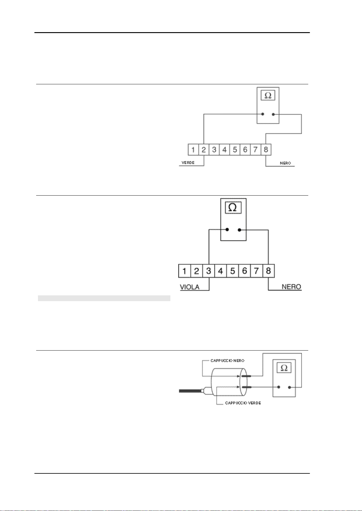
Electrical system Vespa GT 125-200
Electric characteristic
Pick-up resistance value
Pick-up resistance value: 105 ÷ 124 Ohm
If a break in the circuit is found, check again the
flywheel and the engine ground connectors (see
engine manual). If non-conforming values are
measured, replace the Pick-Up; otherwise, repair
the cable harness.
In case conforming values are measured, try replacing the control unit (without programming) and
make sure the failure has been solved by checking
sparks are produced in the spark plug; only then
program the control unit.
- HV coil primary check
Disconnect the control unit connector and check
that the cable between terminal No. 3 and terminal
No. 8 is not interrupted (see figure).
If non-conforming values are measured, check
again the HV coil primary directly on the positive
and negative terminals.
If non-conforming values are measured, repair the
cables or replace the HV coil.
N.B.
THE MULTIMETER MUST BE SELECTED TO DETECT
CONTINUOUS VOLTAGE.
Electric characteristic
Resistance value:
0.4 ÷ 0.5 Ohm
- HV coil secondary check
Disconnect the spark plug cap from the HV cable
and measure the resistance between the HV cable
terminal and the HV coil negative terminal (see
figure).
If non-conforming values are measured, replace
the HV coil. To carry out a more complete diagnosis, check the peak voltage with the multimeter
adaptor.
Specific tooling
ELE SYS - 76
Page 77

Vespa GT 125-200 Electrical system
020409Y Multimeter adaptor - Peak voltage detection
Electric characteristic
Resistance value:
~ 3000 ± 300 Ohm
- Pick-Up
Disconnect the control unit connector and connect
the positive wire to connector No. 2 and the negative wire to connector No. 8 (see figure).
Use the start-up system to run the engine and
measure the voltage produced by the Pick-Up.
Replace Pick-Up if non-conforming values are
measured.
N.B.
THE MULTIMETER MUST BE SELECTED TO DETECT
CONTINUOUS VOLTAGE.
Electric characteristic
Resistance value:
> 2 Volt
- HV coil
With the control unit and HV coil connected, measure the voltage of the coil primary during the startup test with the voltage peak adaptor and connecting the positive terminal to the ground one and
the negative to the coil positive connector.
If non-conforming values are measured, replace
the control unit.
N.B.
THE PLASTIC CAP OF THE POSITIVE TERMINAL ON THE
HV COIL PRIMARY IS BLACK AND THE NEGATIVE TERMINAL ONE IS GREEN.
Electric characteristic
Resistance value:
> 100 Volt
Battery recharge circuit
The recharge system is provided with a three phase alternator with permanent flywheel.
The alternator is directly connected to the voltage regulator.
In turn, the latter is directly connected to earth and to the battery positive passing through the 15A safety
fuse.
This system therefore requires no connection to the key switch.
ELE SYS - 77
Page 78

Electrical system Vespa GT 125-200
The three- phase generator provides good recharge power and at low revs a good compromise is
achieved between generated power and idle stability.
For this reason, it is very important that the idle speed is adjusted as prescribed.
Specific tooling
020333Y Single battery charger
020334Y Multiple battery charger
Stator check
Disconnect the connector from the voltage regulator and check there is continuity between any yellow
cable and the other two cables.
Electric characteristic
Ohm value:
0.7 ÷ 0.9 Ohm
Also check that all yellow cables are insulated from
the ground connection.
If non-conforming values are detected, repeat the
checks directly to the stator. In case of further repetitions of incorrect values replace the stator or
repair the wiring.
ELE SYS - 78
Page 79

Vespa GT 125-200 Electrical system
- With a tester, check the circuit between connections 5-3 and 5-1 is not interrupted.
- Check the earth isolation on the three phases of
stators 5-earth, 3-earth, 1-earth.
Stage indicative resistance: 0.7 - 0.9 Ω
Minimum oil pressure switch check
- With a tester, check the circuit between connections 4 and ground (with engine off) is not interrupted.
Pick-Up check
- Check that there is a resistance of about 105 ÷
124 Ω at 20° C between connection 2 and ground.
- In case of values different from the ones stated,
replace the defective parts.
N.B.
VALUES ARE STATED AT AMBIENT TEMPERATURE. A
CHECK WITH THE STATOR AT OPERATING TEMPERATURE MAY RESULT IN VALUES HIGHER THAN THOSE
STATED.
Voltage regulator check
With a perfectly charged battery and lights off,
measure voltage at the battery poles with a high
running engine.
The voltage should not exceed 15.2 Volt.
In case higher voltages are detected, replace the
regulator.
In case of voltage values lower than 14 Volt, check
the stator and the corresponding cable harness.
ELE SYS - 79
Page 80

Electrical system Vespa GT 125-200
Recharge system voltage check
Connect an ammeter induction clamp to the voltage regulator positive terminal, measure the battery voltage and turning on the vehicles lights with
engine off, wait for the voltage to set at about 12
V. Start the engine and measure the current generated by the system with lights on and a high
running engine.
In case the generated current value is lower than
10A, repeat the test using a new regulator and/
stator alternatively.
Choke Inspection
For the component resistive and functional check,
see the engine section. As regards its power supply, keep the system connector connected and
check the presence of battery voltage at the two
terminals with engine running (see figure).
If there is no voltage, connect the multimeter negative terminal to earth and the positive terminal to
the orange wire of the automatic starter device;
with key switch set to «ON» check the presence of
battery voltage; in case of negative result, check
the wiring to the key switch and the functionality of
the 15° fuse (N° 8).If voltage is present, repeat the
check from the ignition control unit connector.
After disconnecting the starter, start the engine
and keep it idle then check the presence of voltage
connecting the multimeter with positive terminal to
the terminal no. 5 (light blue) and negative to terminal no. 7 (white-black) (see figure).
If there is no voltage, replace the control unit after
checking the integrity of the fuses; otherwise,
ELE SYS - 80
Page 81

Vespa GT 125-200 Electrical system
check the wiring between starter and control unit,
or finally, as last option replace the starter.
Turn signals system check
- If the turn indicators do not work, proceed as follows:
-Disconnect the control unit connector and check that there is battery voltage between terminal No.4
(Red/Black) and the ground lead.
-Check that the same happens between terminal No. 4 and terminal No. 8 (Black).
-Repeat the check between terminal No. 5 (Sky blue) and terminal No. 8 (Black) with the key switch set
to "ON", with the emergency switch set to "RUN".
If no voltage is detected, check the cable harness, the connections and make sure the 15A main fuse
is in good conditions; otherwise, proceed as follows:
- Jump terminals No.1 (Black/Blue) and No. 4 (Red/Black) (see figure), and set the turn indicator switch
alternately to the left and to the right and check that the lights turn on.
If they do, replace the control unit because it is faulty.
If they do not turn on, check the control unit-turn indicator switch connection cable harness; then, repeat
the test.
If the cable harness is in good conditions and the turn indicators still do not turn on, replace the turn
indicator switch because it is faulty.
ELE SYS - 81
Page 82

Electrical system Vespa GT 125-200
Fuses
The electrical system is equipped with:
1. six protection fuses «A» located in the glove
compartment to the left
2. one 15A fuse «B» located under the helmet
compartment under the saddle hinge latch.
The chart shows the position and characteristics
of the fuses in the vehicle.
CAUTION
BEFORE REPLACING THE BLOWN FUSE,
SEARCH AND SOLVE THE PROBLEM THAT
CAUSED IT TO BLOW.
NEVER TRY TO REPLACE A BLOWN FUSE
WITH A FUSE OF A DIFFERENT RATING THAN
THAT SPECIFIED OR USING OTHER MATERIAL (FOR EXAMPLE, A PIECE OF ELECTRICAL
WIRE).
FUSES
Specification
1 Rear side/taillight, number
plate holder, instrument
lighting and instrument
light indicator.
2 Stop light bulb, remote
control start switch enable
signal
3 Intercom fitting, antitheft
fitting, water temperature
indicator, fuel reserve indi-
cator, oil pressure indica-
tor and fuel reserve light
Desc./Quantity
Order on terminal hold-
er: 1
Fuse: 5A
Protected circuits: Rear
side/taillight, number plate
holder, instrument lighting
and instrument light indi-
cator.
Order on terminal hold-
er: 2
Fuse: 5A
Protected circuits: Stop
light bulb, remote control
start switch enable signal
Order on terminal hold-
er: 3
Fuse: 7,5A
Protected circuits: Inter-
com fitting, antitheft fitting,
ELE SYS - 82
Page 83

Vespa GT 125-200 Electrical system
Specification Desc./Quantity
water temperature indicator, fuel reserve indicator,
oil pressure indicator and
fuel reserve light
4 Horn Order on terminal hold-
Protected circuits: Horn
5 Intercom fitting, antitheft
fitting, immobilizer led
6 Electric saddle opener,
dipped/full headlights, full
headlight indication light
7 General Order on terminal hold-
Order on terminal hold-
Protected circuits: Inter-
com fitting, antitheft fitting,
Order on terminal hold-
Protected circuits: Elec-
tric saddle opener, dipped/
full headlights, full head-
Protected circuits: Gen-
er: 4
Fuse: 7,5A
er: 5
Fuse: 7,5A
immobilizer led
er: 6
Fuse: 10A
light indication light
er: 7
Fuse: 15A
eral
Dashboard
A = Digital clock with calendar
B = Cooling liquid temperature gauge
C = Right turn indicator warning light
D = Fuel gauge
E = Headlight warning light
F = High-beam warning light
G = Low oil pressure warning light
H = Low fuel warning light
I = Speedometer
L = Odometer
M = Left turn indicator warning light
N = Antitheft device LED (immobilizer)
Specification
1 Fuel gauge signal
2 High-beam warning light
3 Oil warning light
4 Fuel supply (+)
5 Low fuel warning light
6 Lighting
A
Desc./Quantity
Specification
1 Ground lead
2 Left turn indicator
B
Desc./Quantity
ELE SYS - 83
Page 84

Electrical system Vespa GT 125-200
Specification Desc./Quantity
3 Right turn indicator
4 Temperature signal
Dry-charge battery
Battery recharge
Normal bench charging must be carried out using the special (single or multiple) battery charger, setting
the battery charge selector to the type of battery that needs recharging (i.e., at a current equal to 1/10
of the battery rated capacity). Connections to the power supply source must be implemented by connecting corresponding poles (+ to + and - to - ).
WARNING
BEFORE RECHARGING THE BATTERY, REMOVE THE CAPS OF EACH CELL.
KEEP THE BATTERY AWAY FROM NAKED FLAMES OR SPARKS WHILE IT IS CHARGED.
FIRST DETACH THE NEGATIVE LEAD BEFORE REMOVING THE BATTERY FROM THE VEHICLE.
Specific tooling
020333Y Single battery charger
020334Y Multiple battery charger
Charging status check
After topping-up the electrolyte level, check the density using special densimeter
When the battery is charged, you should detect a density of 30 to 32 Bé corresponding to a specific
weight of 1.26 to 1.28 at a temperature of no lower than 15° C.
A density reading of less than 20° Bé indicates that the battery is completely flat and it must therefore
be recharged.
If the scooter is not used for a given time (1 month or more) it will be necessary to periodically recharge
the battery.
The battery runs down completely in the course of three months. If it is necessary to refit the battery in
the vehicle, be careful not to reverse the connections, remembering that the ground wire (black) marked
(-) must be connected to the -negative clamp while the other two red wires marked (+) must be connected to the clamp marked with the +positive sign.
ELE SYS - 84
Page 85

Vespa GT 125-200 Electrical system
Battery cleaning
The battery should always be kept clean, especially on its top side, and the terminals should be coated
with Vaseline.
CAUTION
NEVER USE FUSES WITH A CAPACITY HIGHER THAN THAT RECOMMENDED.
USING A FUSE OF UNSUITABLE RATING MAY SERIOUSLY DAMAGE THE VEHICLE OR EVEN
CAUSE A FIRE.
CAUTION
DRINKING WATER CONTAINS MINERALS THAT CAN BE EXTREMELY HARMFUL TO THE BATTERY: USE DISTILLED WATER ONLY.
CAUTION
TO ENSURE MAXIMUM PERFORMANCE THE BATTERY MUST BE CHARGED BEFORE USE.
INADEQUATE CHARGING OF THE BATTERY WITH A LOW ELECTROLYTE LEVEL BEFORE IT
IS FIRST USED SHORTENS THE LIFE OF THE BATTERY.
Checking the electrolyte level
The electrolyte level must be checked frequently and must reach the upper level. Only use distilled
water, to restore this level. If it is necessary to add water too frequently, check the vehicle's electrical
system: the battery works overcharged and is subject to quick wear.
- Remove the short closed tube and the caps, then
pour sulphuric acid into the cells using the type
specified for batteries with a specific gravity of
1.26, corresponding to 30 Bé at a minimum temperature of 15°C until the upper level is reached.
- Allow to stand for at least 2 hours, then top up the
level with sulphuric acid.
- Within the following 24 hours, recharge with the
specific (single) or (multiple) battery charger at an
intensity approx. to 1/10 of the battery rated capacity and until the acid density is approximately
1.27, corresponding to 31º Bé, and these values
are stabilised.
- After charging, level the acid (adding distilled
water). Close and clean carefully.
- Once the above operations have been performed, install the battery in the vehicle ensuring
that it is wired up properly.
Specific tooling
020333Y Single battery charger
ELE SYS - 85
Page 86

Electrical system Vespa GT 125-200
020334Y Multiple battery charger
1 Hold the vertical tube
2 Look at the level
3 The float must be freed
Battery installation
• Remove the battery cover after undoing the 4
screws shown in the photograph.
- Remove the strap fastening the battery
- Insert the battery breather pipe through the hole
shown in the photograph.
ELE SYS - 86
Page 87

Vespa GT 125-200 Electrical system
- Fit the battery as shown in the photograph.
N.B.
IN ORDER TO FIT THE CABLES ON THE BATTERY TER-
MINALS CORRECTLY, REST THE LOWER END OF THE
TERMINAL SIDE OF THE BATTERY ON THE EDGE OF THE
BATTERY WELL.
- Using the screwdriver, tighten up the battery terminal cables as far as they will go, placing the
special Grover washer between the screw head
and the cable terminal.
N.B.
DO NOT USE WRENCHES TO TIGHTEN UP THE SCREWS
FOR FIXING THE TERMINALS TO THE BATTERY TERMINALS
- Mount permanently the battery in the battery
chamber
- Refit the strap fastening the battery
ELE SYS - 87
Page 88

Electrical system Vespa GT 125-200
- Refit the battery cover
ELE SYS - 88
Page 89

INDEX OF TOPICS
ENGINE FROM VEHICLE ENG VE
Page 90

Engine from vehicle Vespa GT 125-200
This section describes the operations to be carried out when removing the engine from the vehicle.
Exhaust assy. Removal
- Undo the two exhaust manifold fixings on the
head.
- Undo the three screws that fix the muffler to the
support arm.
- Remove the full muffler unit.
Removal of the engine from the vehicle
-Carry out the removal operations but in reverse order and respect the locking torques indicated in the
Characteristics Chapter.
Check that there is a small clearance when the valve is in abutment against the set screw.
-Check the engine oil level and if necessary top it up with the recommended type.
- Top-up the cooling circuit.
- Check the functioning of the accelerator and the electrical devices.
CAUTION
PAY PARTICULAR ATTENTION TO POSITIONING THE THROTTLE CONTROL TRANSMISSION
PROPERLY.
ENG VE - 90
Page 91

Vespa GT 125-200 Engine from vehicle
- Disconnect the battery
- Remove the helmet compartment
- Remove the side fairings
Remove the full muffler assembly.
- Remove the air cleaner housing acting on the 3
screws indicated in the picture, by removing the
clamp from the blow-by pipe and disconnecting the
bellow connection to the carburettor acting on the
clamp as indicated in the photograph
CAUTION
THIS OPERATION MUST BE CARRIED OUT WHEN THE
ENGINE IS COLD.
- Remove the air intake manifold on the transmission housing acting on the two screws indicated in
the photograph and remove the plastic clip
ENG VE - 91
Page 92

Engine from vehicle Vespa GT 125-200
- Remove the coolant inlet pipe to the pump as indicated in the photograph.
- Remove the fuel valve vacuum intake pipe from
"T" joint indicated in the photograph
- Remove the fuel supply pipe from the carburettor
- Remove the coolant outlet pipe from the engine
and the bleed pipe indicated in the photograph
ENG VE - 92
Page 93

Vespa GT 125-200 Engine from vehicle
- Remove the spark plug cap
- Remove the coolant temperature sensor connector indicated in the photo
- Remove the throttle control cable from the carburettor acting on the nut shown in the photo
- Remove the automatic starter connector from the
system located inside the protection sheath shown
in the photo
ENG VE - 93
Page 94

Engine from vehicle Vespa GT 125-200
- Remove the positive and negative wires from the
starter motor as shown in the photograph
- Remove the connector from the flywheel wiring
shown in the photograph.
- Remove the cable from the retainer clamp on the
flywheel cover
- Remove the rear shock absorbers.
- Remove the hydraulic piping from the rear calliper by undoing the screw indicated in the photograph. Then remove the retainers fixing the piping
to the engine crankcase, indicated in the photograph.
ENG VE - 94
Page 95

Vespa GT 125-200 Engine from vehicle
- Use a jack to support the vehicle properly. Remove the engine-swinging arm fixing pin by acting
on the nut and the head of the pin indicated in the
photograph
- The engine is now free.
ENG VE - 95
Page 96

INDEX OF TOPICS
ENGINE ENG
Page 97

Vespa GT 125-200 Engine
This section describes the operations to be carried out on the engine and the tools to be used.
Automatic transmission
Transmission cover
- To remove the transmission cover it is necessary
to remove the plastic cover first, by inserting a
screwdriver in the slotted holes. Using the clutch
bell lock wrench shown in the figure, remove the
driven pulley shaft locking nut and washer.
Specific tooling
020423Y driven pulley lock wrench
- Remove the cap/dipstick from the engine oil filling
hole.
- Remove the ten screws.
- Remove the transmission cover.
If this operation is carried out directly on the vehicle, remove the cooling air supply coupling of the
transmission housing.
Air duct
Version 125
- Remove the 4 screws and the housing.
ENG - 97
Page 98

Engine Vespa GT 125-200
- Remove the five screws on two different levels
as well as the small casing.
- To remove the intake throat on the transmission
cover, just remove the 2 fixing screws indicated in
the figure.
Removing the driven pulley shaft bearing
- Remove the clip from the inside of the cover.
- Remove the bearing from the crankcase by
means of:
Specific tooling
020376Y Adaptor handle
020375Y Adaptor 28 x 30 mm
020412Y 15 mm guide
ENG - 98
Page 99

Vespa GT 125-200 Engine
Refitting the driven pulley shaft bearing
- Slightly heat the crankcase from the inside so as
not to damage the painted surface.
- Insert the bearing in its seat.
- Refit the seeger ring.
CAUTION
USE AN APPROPRIATE REST SURFACE TO AVOID DAM-
AGING THE COVER PAINT.
N.B.
ALWAYS REPLACE THE BEARING WITH A NEW ONE
UPON REFITTING.
Specific tooling
020376Y Adaptor handle
020357Y 32 x 35 mm adaptor
020412Y 15 mm guide
Baffle roller
Metallic roller
Removal
Belt support roller (200 cm³ models only)
- Check that the roller does not show signs of wear
and that it turns freely.
- Remove the special fixing screw and the roller
together with the bearing.
Refitting
- Heat the roller and insert the bearing using the
specific punch:
Specific tools:
Specific tooling
020455Y 10-mm guide
ENG - 99
Page 100

Engine Vespa GT 125-200
- Refit the roller with the special screw.
- Tighten to the specified torque.
- Refit the intake throat with the O-ring, the sump
sealing gasket and a the fan housing.
Locking torques (N*m)
Anti-flapping roller 12 - 16
Removing the driven pulley
- Remove the spacer, the clutch bell and the whole
driven pulley unit.
N.B.
THE UNIT CAN ALSO BE REMOVED WITH THE DRIVING
PULLEY MOUNTED.
Inspecting the clutch drum
- Check that the clutch bell is not worn or damaged.
- Measure the clutch bell inside diameter.
Characteristic
Max. value clutch bell
Max. value: Ø 134.5 mm
Clutch bell standard value
Standard value: Ø 134 - 134.2 mm
Checking the bell working surface eccentricity
- Install the bell on a driven pulley shaft using 2
bearings (inner diameter 15 and 17 mm).
- Lock with the original spacer and nut.
- Place the bell/shaft assembly on the support to
check the crankshaft alignment.
ENG - 100
 Loading...