

VESPA GT 200, Granturismo GT 200 Workshop Manual

Index
1 Vespa GT 200 16
2 Characteristics 17
2.1 Various 17
2.1.1 Workshop Safety 17
2.1.2 Service Recommendations 17
2.2 Vehicle Identification 18
2.2.1 Frame No. 18
2.2.2 Engine No. 18
2.3 Technical Specifications 19
2.3.1 Weight and Dimensions 19
2.4 Engine 20
2.4.1 General 20
2.4.2 Walbro carburetor 21
2.4.3 Kehin carburetor 22
2.5 Transmission 23
2.6 Capacities 23
2.7 Electrical Components 23
2.8 Frame, Suspensions, Brakes and Tires 24
2.8.1 Frame and Suspension 24
2.8.2 Brakes 24
2.8.3 Wheels and Tires 24
3 Tightening Torques 25
3.1 Steering Unit 25
3.2 Frame 25
3.3 Front Suspension 25
3.4 Front Brake 26
3.5 Rear Suspension 26
3.6 Rear Brake 27
3.7 Silencer 27
2

3.8 Hydraulic Components 27
3.9 Cylinder Head 28
3.10 Transmission 29
3.11 Flywheel 29
3.12 Engine Crankcase and Shaft 29
3.13 Cooling 30
4 Assembly Clearances 31
4.1 Piston–Cylinder Mating 31
4.2 O Rings 32
4.3 Compression Ratio Limiting Shimming System: (11-12:1) 33
4.4 Crankshaft End-Play 34
4.5 Crankshaft Alignment 35
5 Recommended Lubricants 36
6 Special Tools 37
6.1 Steering Bearing Seat Installer – 001330Y 37
6.2 Pliers – 001467Y014 37
6.3 Bell – 001467Y017 37
6.4 Steering Column Ball- Cage Bearing Removing Punch – 020004Y 37
6.5 Front Suspension Overhaul Tool – 020021Y 38
6.6 Punch – 020036Y 38
6.7 Punch - 020038Y 38
6.8 Ring Nut Spanner - 020055Y 38
6.9 Crankshaft Aligner - 020074Y 39
6.10 Heat Gun Support - 020150Y 39
6.11 Heat Gun - 020151Y 39
6.12 Oil Pressure Gauge - 020193Y 39
6.13 Crankcase Detacher - 020262Y 40
6.14 Half-Pulley Assembler - 020263Y 40
6.15 Fitting Punch - 020306Y 40
6.16 Vacuum Pump - 020329Y 40
3

6.17 Timing Light - 020330Y 41
6.18 Digital Multimeter - 020331Y 41
6.19 Digital Tachometer - 020332Y 41
6.20 Single Battery Charger - 020333Y 42
6.21 Multiple Battery Charger - 020334Y 42
6.22 Dial Gauge - 020335Y 42
6.23 Adapter (42×47 mm) - 020359Y 43
6.24 Adapter (52×55 mm) - 020360Y 43
6.25 Guide (20 mm) - 020363Y 43
6.26 Guide (25mm) - 020364Y 43
6.27 Guide (22 mm) - 020365Y 44
6.28 Adapter (28×30 mm) - 020375Y 44
6.29 Handle - 020376Y 44
6.30 Valve Half-Cone Remover - 020382Y 44
6.31 Bushing - 020382Y011 44
6.32 Piston Assembly Band - 020393Y 45
6.33 Multimeter Adapter - 020409Y 45
6.34 Guide (15 mm) - 020412Y 46
6.35 Clutch Drum Lock Wrench - 020423Y46
6.36 Punch - 020424Y 46
6.37 Punch - 020425Y 46
6.38 Piston Fitting Fork - 020426Y 47
6.39 Piston Support - 020428Y 47
6.40 Valve O-Ring Remover - 020431Y 47
6.41 Oil Pressure Gauge - 020434Y 47
6.42 Guide (17 mm) - 020439Y 48
6.43 Water Pump Overhaul Tool - 020440Y 48
6.44 Adapter (26×28 mm) - 020441Y 48
6.45 Stop Wrench - 020442Y 48
6.46 Driven Pulley Spring Tool - 020444Y 49
4

6.47 Guide (30 mm) - 020483Y 49
6.48 Pivot Retainers Installer - 020488Y49
6.49 Hub Cover support - 020489Y 49
6.50 Flywheel Wrench - 020565Y 50
6.51 Engine Support - 002095Y 50
6.52 Pliers - 002465Y 50
6.53 Punch - 06029Y 50
6.54 Flywheel Extractor - 08564Y 51
6.55 Gas Analyzer - 494929 51
7 Maintenance 52
7.1 Maintenance Schedule 52
7.2 Carburetor 54
7.3 Checking and Replacing the Spark Plug 55
7.4 Air Filter 56
7.5 Engine Oil 58
7.5.1 Checking the Engine Oil Level 58
7.5.2 Topping-Up the Engine Oil 59
7.5.3 Replacing the Oil and Oil Filter 59
7.6 Hub Oil 61
7.6.1 Checking the Hub Oil Level 61
7.6.2 Replacing the Hub Oil 61
7.7 Topping-Up the Engine Cooling Liquid 62
7.8 Brake Fluid 63
7.8.1 Checking the Brake Fluid Level 63
7.8.2 Topping-Up the Brake Fluid Level 64
7.9 Removing the Steering Lock 65
7.9.1 Removing the Steering Lock when on «OFF» Position 65
7.9.2 Removing the Steering Lock when on «LOCK» Position 66
7.10 Headlight Adjustment 67
7.11 Checking the Spark Advance 68
5

7.12 Spark Advance Variation Curve 69
7.13 Evaporative emission system 70
Checking the CO Concentration 71
7.14 SAS (Secondary Air System) 73
7.14.1 General 73
7.14.2 Description 73
7.14.3 Removing the SAS 74
8 Troubleshooting 77
8.1 Engine 77
8.1.1 Poor Performance 77
8.1.2 Rear Wheel Spins at Idle 78
8.1.3 Rich Mixture 78
8.1.4 Weak Mixture 79
8.1.5 Low Compression 79
8.1.6 Starting Problems 80
8.1.7 Excessive Oil Consumption/Excessive Smoke from Exhaust 81
8.1.8 Insufficient Lubrication Pressure 81
8.1.9 Engine Tends to Cut Out at Full Throttle 82
8.1.10 Engine Tends to Stop at Idle 82
8.1.11 Excessive Fuel Consumption 83
8.2 Transmission and Brakes 83
8.2.1 Irregular Clutch Operation or Grapping 83
8.2.2 Poor Braking Performance 84
8.2.3 Brakes Overheating 84
8.3 Electrical System 85
8.3.1 Battery 85
8.3.2 Turn Signal Lights Not Working 85
8.4 Steering Controls and Suspension 85
8.4.1 Excessive Steering Stiffness 85
8.4.2 Excessive Steering Play 85
6

8.4.3 Noisy Suspension 86
8.4.4 Suspension Oil Leaking 86
Electrical System 87
9.1 Electrical Diagrams 89
9.1.1 Ignition Section 89
9.1.2 Turn Signal Lights, Horn, Services and Accessory Pre - Wiring 90
9.1.3 Level Indicators and Safety Switches92
9.1.4 Battery Recharge and Starting Section 93
9.1.5 Headlight and Automatic Choke Section 94
9.2 Electrical Equipment 95
9.2.1 Electronic Ignition (Immobilizer System) 95
9.2.2 Un-Coded Electronic Ignition System97
9.2.3 Diagnostic Codes 98
9.2.4 2-Flash Diagnostic Code 98
9.2.5 3-Flash Diagnostic Code 99
9.2.6 Ignition System 99
9.2.7 Spark Plug Power Supply Failure 100
9.2.8 Battery Charging System 101
9.2.9 Checking the Voltage Regulator 102
9.2.10 Stator check 102
9.2.11 Checking the Regulator 103
9.2.12 Checking the Automatic Choke Section 103
9.2.13 Turn Signal Lights Fail to Operate 104
9.2.14 Fuses 105
9.2.15 Instrument Panel 106
9.2.16 Battery 107
9.2.16.1 Preparing the Battery 107
9.2.16.2 Checking the Electrolyte Level 107
9.2.16.3 Checking the Electrolyte Density 107
9.2.16.4 Checking the Battery Charge Level108
7

9.2.16.5 Cleaning the Battery 108
9.2.16.6 Installing the Battery 108
10 Engine 111
10.1 Disassembling the Engine from the Frame 111
10.2 Removing the Silencer 116
10.3 Refitting the Engine onto the Frame 116
10.4 Removing the Rocker Cover 117
10.5 Refitting the Rocker Cover 117
10.6 Checking the Compression 117
10.7 Transmission 118
10.7.1 Removing the Transmission Cover118
10.7.2 Removing the Fan Case 118
10.7.3 Removing the Transmission Cooling Intake 119
10.7.4 Removing the Driven Pulley Shaft Bearing 119
10.7.5 Fitting the Driven Pulley Shaft Bearing 119
10.7.6 Removing the Belt Support Roller 120
10.7.7 Refitting the Belt Support Roller 120
10.7.8 Removing the Driving Pulley 121
10.7.9 Removing the Driven Pulley 121
10.7.10 Inspecting the Clutch Drum 122
10.7.11 Checking the Clutch Drum Surface Eccentricity 122
10.7.12 Removing the Clutch 123
10.7.13 Disassembling the Fixed Driven Half - Pulley Bearings 123
10.7.14 Checking the Fixed Driven Half- Pulley 124
10.7.15 Checking the Moving Driven Half-Pulley 125
10.7.16 Fitting the Fixed Driven Half-Pulley Bearings 125
10.7.17 Refitting the Driven Pulley 126
10.7.18 Checking the Moving Driven Half-Pulley Spring 127
10.7.19 Checking the Drive Belt 127
10.7.20 Checking the Clutch Friction Material128
8

10.7.21 Fitting the Clutch 128
10.7.22 Checking the Moving Driving Half-Pulley 129
10.7.23 Fitting the Fixed Driving Half-Pulley and Bushing Assembly 130
10.7.24 Fitting the Moving Half-Pulley Assembly 131
10.7.25 Fitting the Clutch Drum 132
10.7.26 Fitting the Transmission Cover 133
10.7.27 Removing the Rear Hub Cover 133
10.7.28 Removing the Rear Wheel Axle 134
10.7.29 Checking the Hub Casing Bearings 134
10.7.30 Removing the Wheel Axle Bearing from the Cover 135
10.7.31 Removing the Driven Pulley Shaft 136
10.7.32 Checking the Hub Cover 136
10.7.33 Fitting the Hub Casing Bearings 136
10.7.34 Fitting the Wheel Axle Bearing on the Cover 137
10.7.35 Checking the Hub Shafts 138
10.7.36 Fitting the Hub Gears 139
10.7.37 Fitting the Hub Cover 139
10.8 Flywheel 140
10.8.1 Removing the Flywheel Cover Assembly 140
10.8.2 Removing the Flywheel 143
10.8.3 Removing the Stator 144
10.8.4 Checking the Stator 144
10.8.5 Checking the Low Oil Pressure Switch 145
10.8.6 Checking the Pick-Up 145
10.8.7 Checking the Flywheel 145
10.8.8 Fitting the Stator Assembly 145
10.8.9 Fitting the Flywheel 146
10.8.10 Fitting the Flywheel Cover Assembly 146
10.9 Checking the Secondary Air Box Valve 148
10.9.1 Checking the One- Way Valve 149
9

10.10 Lubrication Circuit 151
10.10.1 Checking the Oil Pressure 152
10.10.2 Removing the Oil Sump and Pressure Adjusting By-Pass Valve 153
10.10.3 Checking the By-Pass Valve 153
10.10.4 Removing the Oil Pump 154
10.10.5 Checking the Oil Pump 155
10.10.6 Fitting the Oil Pump 156
10.10.7 Fitting the Chain Cover Oil Seal 157
10.10.8 Fitting the By- Pass and the Oil Sump 159
10.10.9 Removing the Intake Manifold 159
10.10.10 Thermostat Removal 160
10.10.11 Removing the Timing Chain Sprockets 160
10.10.12 Removing the Camshaft and Rockers 161
10.10.13 Removing the Cylinder Head 162
10.10.14 Removing the Valves 163
10.10.15 Removing the Cylinder and Piston Assembly 163
10.10.16 Inspecting the Small End 164
10.10.17 Inspecting the Wrist Pin Diameter165
10.10.18 Inspecting the Piston and Cylinder Diameters 165
10.10.19 Inspecting the Piston 166
10.10.20 Checking the Piston Ring Gap 167
10.10.21 Fitting the Piston 168
10.10.22 Choosing the Base Gasket Thickness 168
10.10.23 Fitting the Piston Rings 170
10.10.24 Fitting the Cylinder 170
10.10.25 Inspecting the Cylinder Head 171
10.10.26 Checking the Valve Seals 171
10.10.27 Inspecting the Valve Seats 172
10.10.28 Inspecting the Valves 172
10.10.29 Testing the Valve Seals 174
10

10.10.30 Checking the Valve Spring Plates and Half-cones 174
10.10.31 Fitting the Valves 174
10.10.32 Inspecting the Timing Components175
10.10.33 Inspecting the Camshaft 176
10.10.34 Fitting the Cylinder Head 177
10.10.35 Fitting the Timing Components 178
10.10.36 Fitting the Thermostat 181
10.10.37 Fitting the Intake Manifold 181
10.11 Crankshaft 182
10.11.1 Preparing the Engine for Crankcase Separation 182
10.11.2 Separating the Crankcase Halves 183
10.11.3 Checking the Crankshaft 184
10.11.4 Checking the Crankcase Halves 186
10.11.5 Checking the Main Bearings 187
10.11.6 Assembling the Crankcase Halves 188
10.11.7 Fitting the Starter Motor 190
10.11.8 Removing the Carburetor 191
10.11.8.1 Kehin CVK 30 Carburetor 191
10.11.8.2 Walbro WVF-7P Carburetor 197
10.11.9 Re-assembling the carburetor 204
10.11.9.1 Kehin CVK 30 Carbu retor 204
10.11.9.2 Walbro WFV-7P Carburetor 206
10.11.10 Checking the Float Height 208
10.11.10.1 Kehin CVK 30 Carburetor 208
10.11.10.2 Walbro WVF-7P Carburetor 210
10.11.11 Checking the Vacuum Valve and the Needle 212
10.11.11.1 Kehin CVK 30 Carburetor 212
10.11.11.2 Walbro WVF-7P Carburetor 214
10.11.12 Checking the Automatic Choke Device 215
10.11.12.1 Kehin CVK 30 Carburetor 215
11

10.11.12.2 Walbro WVF-7P Carburetor 217
10.12 Cooling System 219
10.12.1 Cooling Circuit 219
10.12.2 Removing the Water Pump 220
10.12.3 Checking the Components 221
10.12.4 Fitting the Water Pump 222
10.12.5 Checking the Thermostat 224
11 Suspensions 225
11.1 Removing and Refitting the Front Wheel 226
11.2 Removing and Refitting the Rear Wheel 226
11.3 Removing the Steering Column 227
11.4 Removing the Front Wheel Hub 230
11.5 Front Wheel Hub Overhaul 230
11.6 Removing the Front Brake Caliper-Shock Absorber Bracket 232
11.7 Front Brake Caliper-Shock Absorber Bracket Overhaul 233
11.8 Removing the Front Shock Absorber235
11.9 Front Swing Arm Overhaul 235
11.10 Steering Column Ball-Cage Bearings Overhaul 237
11.11 Removing the Rear Shock Absorber-Silencer Bracket 240
11.12 Rear Shock Absorbers 241
11.12.1 Removing the Rear Shock Absorbers 241
11.12.2 Refitting the Rear Shock Absorbers 242
11.13 Central Stand 242
11.14 Inspecting the Rear Swing Arm 242
11.15 Swing Arm Overhaul 245
11.16 Silent - Block Overhaul 247
12 Bodywork 250
12.1 Removing the Seat 250
12.2 Removing the Steering Column Cover 250
12.3 Removing the Front Handlebar Cover250
12

12.4 Removing the Rear Handlebar Cover251
12.5 Removing the Instrument Panel 251
12.6 Removing the Glove-box Panel 252
12.7 Removing the Battery Compartment Cover 254
12.8 Removing the Side Fairings 254
12.9 Removing the Footrest 254
12.10 Removing the Luggage Carrier 256
12.11 Removing the Taillight 257
12.12 Removing the Helmet Compartment 257
12.13 Removing the Front Fender 258
12.14 Removing the Fuel Tank 258
12.15 Removing the Radiators and the Cooling Fan 260
12.16 Removing the Rear Mudguard 261
12.17 Removing the Turn Signal Lights 261
12.18 Removing the Electrical Opening Seat System 262
13 Pre- Delivery Inspections 264
13.1 Checking the Vehicle Appearance 264
13.2 Checking the Tightening Torques 264
13.3 Checking the Electrical Circuit 264
13.4 Checking the Levels 265
13.5 Road Test 265
13.6 Static Test 265
13.7 Functional Check 266
Time Sheets 267
14.1 Engine 267
14.2 Crankcase 267
14.3 Crankshaft 267
14.4 Piston- Cylinder Assembly 268
14.5 Cylinder Head and Valves 268
14.6 Camshaft 268
13

14.7 Valve Cover 269
14.8 Chain Tensioner - By-Pass Valve 269
14.9 Oil Filter 269
14.10 Driven Pulley 270
14.11 Pump Assembly - Oil Sump 270
14.12 Rear Wheel Axle 271
14.13 Driving Pulley 271
14.14 Electric Starter 272
14.15 Kick-Starter, Transmission Cover, and Transmission Cooling 272
14.16 Transmission Cooling Air Inlet 272
14.17 Flywheel Magneto 273
14.18 Carburetor 273
14.19 Air Filter 274
14.20 Silencer 274
14.21 Frame 275
14.22 Central Stand 275
14.23 Footrest and Battery 276
14.24 Glove- Box 276
14.25 Helmet Compartment and Rear Fender 277
14.26 Front Fender and Rear Mudguard 277
14.27 Fuel Tank 277
14.28 Cooling System 278
14.29 Fuel Pump 278
14.30 Steering Column 279
14.31 Front Suspension 279
14.32 Rear suspension 280
14.33 Handlebar Covers 280
14.34 Handlebar, and Brake and Throttle Controls 281
14.35 Swing Arm 281
14.36 Brakes 282
14

14.37 Saddle and Rear Rack 283
14.38 Locks and Immobilizer 283
14.39 Mirrors, Electric Controls, and Instrument Panel 284
14.40 Lights 285
14.41 Electrical Devices 286
14.42 Front Wheel 287
14.43 Rear Wheel 287
15
1 Vespa GT 200
This manual has been prepared by Piaggio USA, Inc., a subsidiary of Piaggio & C. S.p.A., for
use in the workshops of authorized Piaggio ® dealers and sub-agents
It is assumed that the person utilizing this manual for servicing or repairing Piaggio® vehicles
has a knowledge of the principles of mechanics and standard procedures required for general
vehicle repair, therefore information regarding routine procedures has been deliberately
omitted. Any relevant changes concerning the vehicle characteristics or specific repair
operations will be divulged in the form of updates to this manual.
Satisfactory repair or service cannot be achieved without the necessary equipment and tools.
Refer to the pages of this manual concerning specific tools and equipment and the special tools
catalogue.
16

2 Characteristics
This section describes the general characteristics of the vehicle.
2.1 Various
2.1.1 Workshop Safety
For tests performed with the engine running ensure the work is carried out in a well-ventilated
place and, if necessary, using appropriate extractors. Never run the engine in an enclosed
space; exhaust gases are toxic.
Some types of battery use sulphuric acid as an electrolyte. Protect eyes, clothing and skin.
Sulphuric acid is highly corrosive; if it comes into contact with the eyes or the skin, rinse
thoroughly with water and seek immediate medical attention.
The battery produces hydrogen gas, which is extremely explosive. Do not smoke and do not
allow flames or sparks near the battery, especially whilst it is being recharged.
Gasoline is extremely flammable and, under certain conditions, explosive. Do not smoke and do
not allow flames or sparks in the work area.
Cleaning of brake shoes, drums and pads should be done in a well-ventilated area, aiming
compressed air so as to avoid inhaling the dust produced by wear in the friction material. Even
the dust from asbestos- free linings can damage the health.
2.1.2 Service Recommendations
Use genuine Piaggio ® spare parts and recommended lubricants. Use of non-genuine spare
parts may damage the vehicle.
For operations requiring special tools, use only those designed specifically for this engine.
Always replace seals, gaskets and split pins with new ones, during reassembly.
After removing components, clean them with a non-flammable or high flash-point solvent.
Lubricate all contacting surfaces, inspect for taper fit couplings, before reassembling.
Check all components have been correctly fitted and test that they work properly after
reassembly.
Use only Metric - sized tools for removing, repairing and refitting operations. Metric screw
fasteners, nuts and bolts are not interchangeable or compatible with Imperial-sized fasteners.
Use of Imperial-sized tools or fasteners can damage the vehicle.
For repairs that involve disconnecting the vehicle’s electrics, test the connections after
reassembly, especially those to ground and to the battery.
17
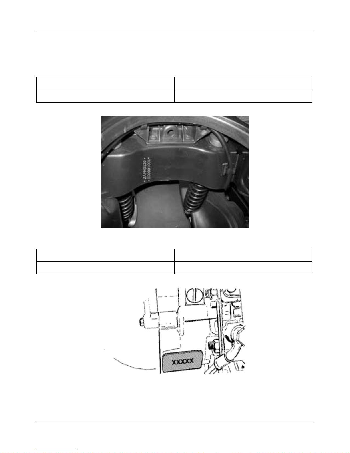
2.2 Vehicle Identification
2.2.1 Frame No.
Vehicle Frame prefix
Granturismo 200 cc ZAPM3120000001001
2.2.2 Engine No.
Vehicle Engine prefix
Granturismo 200 cc M312M1001
18
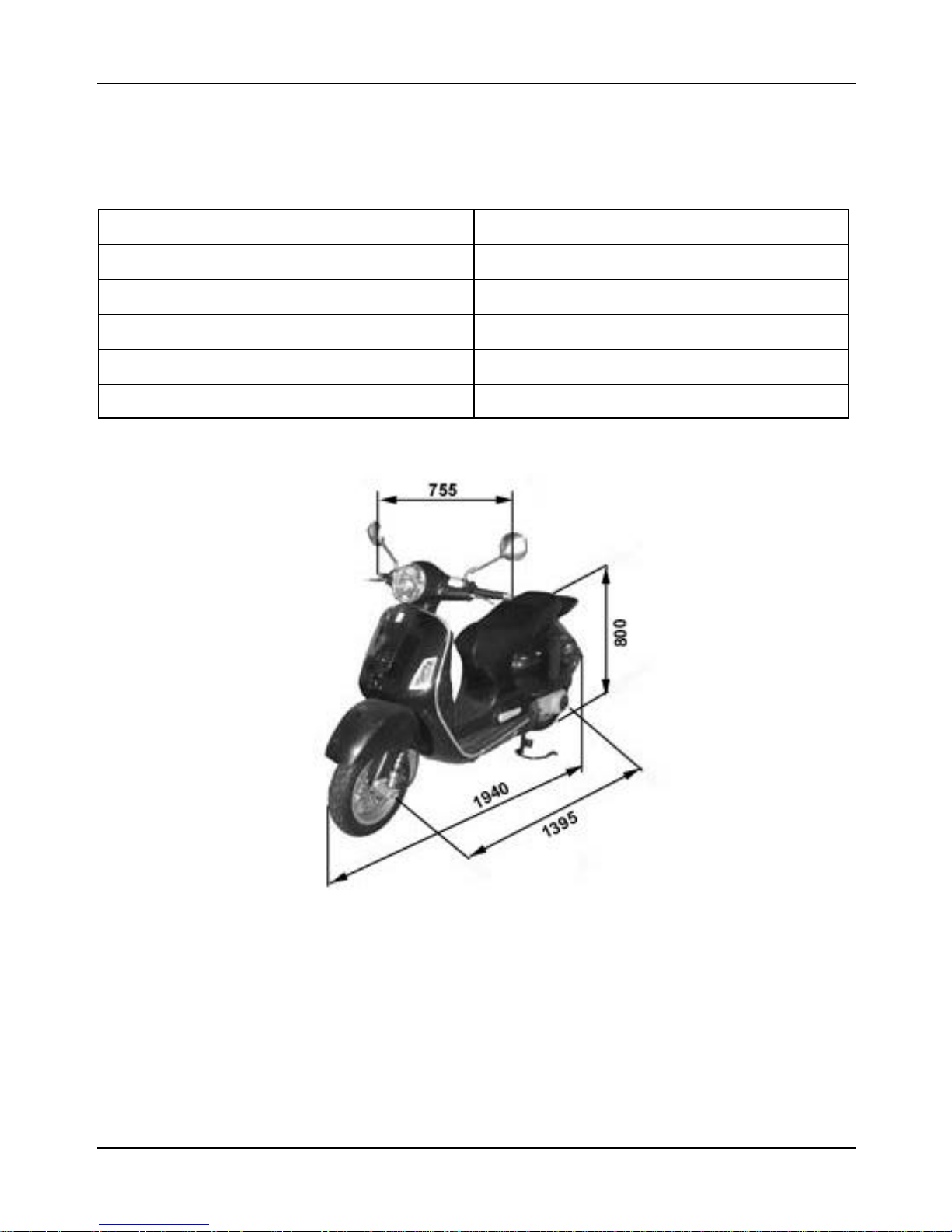
2.3 Technical Specifications
2.3.1 Weight and Dimensions
Characteristics Descriptions
Dry weight 308 lbs. (140 Kg)
Width (at handgrips) 2.48 ft. (755 mm)
Length 6.36 ft. (1,940 mm)
Wheel base 4.58 ft. (1,395 mm)
Saddle height 2.62 ft. (800 mm)
19
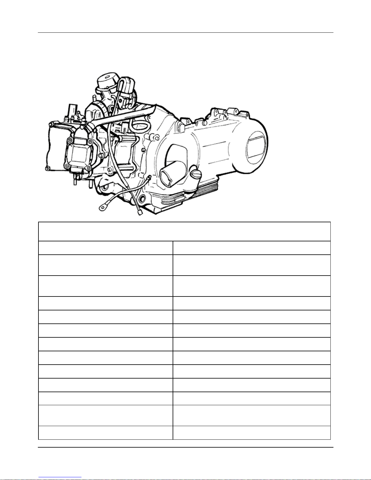
2.4 Engine
2.4.1 General
Characteristics Descriptions
Type Single-cylinder, four-stroke, four-valve, liquid-
cooled
Timing system Single overhead camshaft driven by chain on
L.H., 3-arm rockers with threaded adjuster
Bore 2.83 in. (72.0 mm)
Stroke 1.91 in. (48.6 mm)
Piston displacement 12.06 cu. in. (197.775 cm3)
Compression ratio 11-12: 1
Walbro carburetor WVF-7P
Keihin carburetor CVK 30
Engine idle 1650±50 rpm
CO value 3.8±0.7%
Air filter Sponge air filter, soaked in fuel-oil mixture (50%
Starter system Electric starter motor with torque limiter
gasoline - 50% oil)
20

Lubrication By chain driven lobe pump in crankcase, mesh
strainer and cartridge filter
Fuel system Gasoline supplied by carburetor with vacuum
pump
Max power (shaft) 21 hp (15.4 kW) @ 8,500 rpm
Max speed 75 mph (120 km/h)
2.4.2 Walbro carburetor
Characteristics Descriptions
Vacuum type WVF- 7P*
Printing on body 7P
CUT- OFF device Present
Max jet 95
Slow running jet 33
Main air jet 120
Idling air jet 55
Throttle valve spring 0.264 lbs (1.18 N)
Initial opening of idle speed mixture
2±½
adjusting screw
Conical needle 495
Notches from top of conical needle 2
Diffuser nozzle Ø 0.106 in (2.7 mm)
Fuel inlet hole Ø 0.059 in (1.5 mm)
Starting air jet 200
Starting diffuser jet 110
Starter jet 45
Starter pin diameter Ø 0.070 in (1.78 mm)
Starter device resistance ~40 O
Venturi tube Ø 1.142 in (29.0 mm) - (30.3×27.0 mm)
Throttle valve Ø 1.299 in (33.0 mm)
Tube maximum choke Ø 1.890 in (48.0 mm)
21

2.4.3 Kehin carburetor
Characteristics Descriptions
Vacuum type CVK 30
Printing on body CVK
CUT- OFF device present
Max jet 92
Slow running jet 38
Main air jet 70
Idling air jet 115
Throttle valve spring 0.330–0.551 lbs (1.47–2.45 N)
Initial opening of idle speed mixture
adjusting screw
Conical needle NDAA
Notches from top of conical needle Single-notch needle
Diffuser nozzle Ø 1.969 in (5.0 mm)
Fuel inlet hole Ø 0.059 in (1.5 mm)
Starting air jet
Starting diffuser jet -
Starter jet 42
Choke pin diameter -
Choke device resistance ~ 20 O
Venturi tube Ø 1.142 in (29.0 mm) (47×30.9 mm)
Throttle valve Ø 1.201 in (30.5 mm)
Tube maximum choke -
2¼±¼
-
*The identification letter may vary every time the carburetor is updated.
22

2.5 Transmission
Characteristics Descriptions
Transmission By automatic variator, with expanding pulleys,
torque converter, V-belt, automatic clutch, gear
reducer and transmission compartment cooled
by forced air circulation
2.6 Capacities
Characteristics Descriptions
Engine oil ~1.06 quarts (~1,000 cm3)
(recommended oil: Selenia HI Scooter 4 Tech)
Fuel tank
(including reserve ~0.5 gal)
Rear hub ~0.16 quarts (~150 cm3)
Cooling system fluid ~0.55-0.57 gallons (~ 2.10–2.15 liters)
~2.5 gallons (~9.5 liters)
(recommended oil: TUTELA ZC 90)
(recommended: PARAFLU 11FE (diluted))
2.7 Electrical Components
Characteristics Descriptions
Ignition type Electronic ignition by capacitive discharge, with
variable advance and separate H.T. coil
Variable ignition advance
(before T.D.C.)
Spark plug Champion RG 6 YC
Battery 12V-12Ah
Fuses 1×15A, 1×10A, 3×7.5A, 2×5A
From 10°±1° @ 2,000 rpm
to 32°±1° @ 6,500 rpm
Generator In alternating current (AC)
23

2.8 Frame, Suspensions, Brakes and Tires
2.8.1 Frame and Suspension
Characteristics Descriptions
Type Pressed steel, mono-coque type
Front suspension Single-arm suspension equipped with dual-effect
hydraulic shock absorber with coaxial spring
Front shock absorber travel 3.4 in (86.5 mm)
Rear suspension Engine mounted on oscillating fork pivoted to the
frame by means of an arm with 2 degrees of
freedom. Pair of dual effect hydraulic shock
absorbers and coaxial springs with 3 preload
adjustment positions
Rear shock absorber travel 3.52 in (89.5 mm)
2.8.2 Brakes
Characteristics Descriptions
Front Ø 8.66 in (220 mm) disc and hydraulically
operated floating caliper (via RH lever) with two
Ø 0.98 in (25 mm) pistons
Rear Ø 8.66 in (220 mm) disc and hydraulically
operated floating caliper (via LH lever) with two
Ø 1.18 in (30 mm) pistons
2.8.3 Wheels and Tires
Characteristics Descriptions
Aluminum alloy rims Front: 3.00×12”
Rear: 3.00×12”
Tires Front: 120/70-12” Tubeless
Rear: 130/70-12” Tubeless
Tire pressure (when cold): Front: 26.1 psi (1.8 bars)
Rear (rider only): 29.0 psi (2.0 bars)
Rear (rider + passenger): 31.9 psi (2.2 bars)
Note: The tire inflation pressure should be checked and adjusted when the tires are at
ambient temperature. Pressure should be adjusted according to the weight of the driver,
accessories, and/or passenger.
24

3 Tightening Torques
3.1 Steering Unit
Component Qty Torque [lbs·ft (N·m)]
Steering upper ring nut 1
Steering lower ring nut 1
Handlebar clamping screw (*) 1
Handlebar control unit U-bolts fixing screws 2
22.1–29.5
(30–40)
5.9–7.4
(8–10)
33.1–36.8
(45–50)
5.1–7.4
(7–10)
3.2 Frame
Component Qty Torque [lbs·ft (N·m)]
Swing arm-engine pivot nut 1
Swing arm-frame pivot nut 1
Frame –engine link nut 1
47.1–53.0
(64–72)
56.0–61.1
(76–83)
24.3–30.2
(33–41)
Silent- block support plate bolt 2
Center stand bolt 1
30.9–38.3
(42–52)
18.4–22.1
(25–30)
3.3 Front Suspension
Component Qty Torque [lbs·ft (N·m)]
Shock absorber plate–caliper fixing screw 2
Wheel axle nut 1
Wheel screw 5
Mudguard–fork fixing screw 3
25
14.7–19.9
(20–27)
55.2–66.3
(75–90)
14.7–18.4
(20–25)
3.7–4.8
(5-6.5)

3.4 Front Brake
Component Qty Torque [lbs·ft (N·m)]
Pump–oil tube connection 1
Caliper-oil tube connection 1
Caliper-shock absorber plate fixing screw 2
Disk clamping screw (°) 6 4.4 (6)
Oil bleeder screw 1
Pad clamping pin 2
Brake pump basin screw 2
13.7–18.4
(20–25)
13.7–18.4
(20–25)
13.7–18.4
(20–25)
8.8–11.8
(12–16)
13.6–18.4
(19.6-25)
9.6–13.7
(15–20)
3.5 Rear Suspension
Component Qty Torque [lbs·ft (N·m)]
L.H. side shock absorber support platecrankcase fixing screw
2
13.7–18.4
(20–25)
Shock absorber top fastening 2
Shock absorber bottom fastening 2
Rear wheel axle 1
Wheel–hub fixing screw 5
Silencer-shock absorber support arm screws on
engine (*)
26
2
13.7–18.4
(20–25)
24.3–30.2
(33–41)
76.5–92.6
(104–126)
13.7–18.4
(20–25)
13.7–18.4
(20–25)

3.6 Rear Brake
Component Qty Torque [lbs·ft (N·m)]
Pipe-oil tube connection 1
Caliper–oil tube connection 2
Rear disk clamping screw (°) 6
Oil bleeder screw 1
Caliper–engine fixing screw 2
Brake pump basin screw 2
Caliper coupling screw 2
13.7–18.4
(20–25)
13.7–18.4
(20–25)
8.1–9.6
(11–13)
8.8–11.8
(12–16)
13.7–18.4
(20–25)
11.0–14.7
(15–20)
22.1–24.3
(30–33)
3.7 Silencer
Component Qty Torque [lbs·ft (N·m)]
Silencer heat shield fixing screw 4
Exhaust gas inlet screw 1
Silencer–support arm fixing screw 3
3.7–4.4
(5–6)
9.6–11.0
(13–15)
13.7–18.4
(20–25)
3.8 Hydraulic Components
Component Qty Torque [lbs·ft (N·m)]
Hub oil bleeder cap 1
Oil filter–crankcase fixing screw 1
Engine oil-net filter bleeder cap 1
27
11.0–12.5
(15–17)
19.9–24.3
(27–33)
17.7–22.1
(24–30)

Oil filter 1
Oil pump cover screw 2
Oil pump–crankcase fixing screw 2
Oil pump control rim screw 1
Oil pump cover plate screws 2
Oil sump screw 7
Minimum oil pressure sensor 1
5.9–7.4
(8–10)
5.2–6.6
(7–9)
3.7–4.4
(5–6)
7.4–10.3
(10–14)
2.9–4.4
(4–6)
7.4–10.3
(10–14)
8.8-10.3
(12–14)
3.9 Cylinder Head
Component Qty Torque [lbs·ft (N·m)]
Spark plug 1
Head cover screw 5
Head-cylinder fixing nut (*) (§) 4
Head fixing side screw 2
Start up mass screw 1
Adjustment tappet lock-nut 2
Intake manifold screw 2
Timing chain tightening sliding block screw 1
Start up mass bell screw 1
8.8–10.3
(12–14)
4.4–5.2
(6–7)
5.2±0.7 +½ rotation
(7±1 +180°)
8.1–9.6
(11–13)
5.2–6.3
(7-8.5)
4.4–5.9
(6–8)
8.1–9.6
(11–13)
7.4–10.3
(10–14)
8.1–11.0
(11–15)
Timing belt tightening support screw 2
8.1–9.6
(11–13)
28

Timing belt tightening central screw 1
Camshaft retain plate screw 2
3.7-4.4
(5–6)
2.9–4.4
(4–6)
3.10 Transmission
Component Qty Torque [lbs·ft (N·m)]
Belt support roller screw 1
Clutch assy. nut 1
Driving pulley nut 1
Transmission cover screw 13
Driven pulley axle nut 1
8.1–9.6
(11–13)
40.5–44.2
(55–60)
55.2–61.1
(75–83)
8.1–9.6
(11–13)
39.8–44.4
(54–60)
Rear hub cover screw 7
17.7–19.9
(24–27)
3.11 Flywheel
Component Qty Torque [lbs·ft (N·m)]
Flywheel cover fixing screw 4
Stator unit screw (°) 2
Flywheel nut 1
Pick-up fixing screw 2
3.7–4.4
(5–6)
2.2–2.9
(3–4)
38.3–42.7
(52–58)
2.2–2.9
(3–4)
3.12 Engine Crankcase and Shaft
Component Qty Torque [lbs·ft (N·m)]
Engine crankcase inside head screws
(transmission side half shaft)
2
2.9–4.4
(4–6)
Engine crankcase coupling screws 11
8.1–9.6
(11–13)
29

Starter motor screws 2
Crankcase timing chain cover screw (°) 3
8.1–9.6
(11–13)
2.5-3.2
(3.5-4. 5)
3.13 Cooling
Component Qty Torque [lbs·ft (N·m)]
Water pump impeller cover 3
Water pump impeller driving joint screws 3
Thermostat cover screws 2
2.2–2.9
(3–4)
2.2–2.9
(3–4)
2.2–2.9
(3–4)
30
 Loading...