

VESPA Grande Use Maintenance And Consumer Information

.
~
.
\~
u
I!'
.
I
~
)S)E
MA
NTENA
•
•
•
.I
'
..
"'
'
'·
6 • • '
'
n
'
.
USE
MAINTENANCE
AND
CONSUMER
INFORMATION
.
I
. .
•
• •
PIAGGIO

-
2
' .
.
.,
..
'
~
•;,
...
-~.
. . .
.
..
. '
;
t.
i
"
FT
g.
•
..
~·
,,
1
. -
,
....
'.
. .
....
G'
RAND
'E
.,
..
.,! .
.
..
,, ..
.
"''"'!"
..
,, .
·~
;
t:
. "
'
·~
...
,,,q,,,.
..
,,
.~,,.
'
,.
..
.
..
.
;~.:
with
·~·
..
··
blinkers
. . .
,.
'
.~
..
;,
.
,;;.~!}:,,';
•
.. , .... t"
•\
...
,
'.
~:'
. .
..
.
;:i~=~~
'<
•••
..••
,,
._
'"
·:!~"

:
..
'.
-.
. :
'
\
,_
:
';
' :
-~.
'
...
.,
. .
.
, "
Fi
g.
•
. -
..
"
•
2
-
GRANDE
•
-
..
"
•
. '
" . '
•
•
".:
;·
.
•
...
•
•
. '
..
":
...
,.,
...
"
....
'
; ; "
l ; .
'
"
•
. .
3

•
·
Welcome
to
the
fraternity
of
<<
PIAGGIO
>>
riders!
,,
We
would
like
to
express
our
appreciation
for
your
choice,
and
to
thank
y·ou
for
your
preference.
••
Your
GRANDE is
one
of
our
most
recent
developments.
It
is the resu.
lt
o'f
the
most
advanced
techniques,
and the
product ·of
our
long
experience
.
.
This means
that
you own· a brand new,
carefully
tested,
elegant
ma·c·hine,
full
of
power,
which
will
give
you
lots
of
enjoyment
. We
recommend
'.
you
carefully
follow
the
instructions
contained
herein in
order
to
obtain
the· best
results.
. .
..
This way, Y·
OU
will
come
to
know
your
GRANDE and
will
enable you
to
aP,pre-
ciate
its
tecnical
features
by
using
it
in the
correct
manner
.
NOTE
•
We recommer1d
that
you always
entrust
your
dealer
to
maintain
your
GRAN-
DE
in pe1rfect
C·Ondition and
to
fully
benefit
from
the
garantee
gi~en
in
your
purchase
contract.
~
You
will
easily
recognize
them
from
the
trade
mark
PIAGGIO.
..
Original
Piaggio
spare
parts
are made
from
the same
materia
l as the
~riginal
parts
· on y·
our
G·RANDE. They have b1een made in the same way, and they
have
been· tested in the same way.
This
guarante
es
longer
life, maximum
efficiency
and a
safer
machine
.
We
therefore
recon1mend you
to
demand
only
original
PIAGGIO spare parts.
4
MANUFACTURERS
OF
VESPA
SCOOTERS
'
SERVICE
·

STEERING LOCK
•
To
lock
handl eba
r,
turn
it
fully
to
the
left
..
side,
turn the key
anti.-clockwi
se
at
the
same
time pres
sing it·. Remove
the
key.
To
release ha
ndlebar. turn
the
key
anti-
clockwise then clockwi'se.
The
key can be
withdrawn
when
the
han -
dlebar
is in the
unlocked
position.
Caret
u/ly
record
the
key
number
of
your
machine
as
without
thi
s you
will
be
una-
ble
to
obtain replacement
keys
should
the o·ccasion
arise.
NOTE
Before refuelling, slacken the air
breather, located
at
the rear of the
frame, beneath the
saddle.
After the refuelling, re-tighten the
valve.
5

•
•
..
PERFORMANCE AND GENERAL CHARACTERISTICS
Operati1on
with
2%
pure
SAE
30
oil
~ix-
Carryi1ng
capacity:
2 ·
persons
tu
re
.
.
Fuel
consumption:
(CUNA
standards)
140
mpg. approx
.
Max.
speed:
co·nforming
to
highway
code
Fue
·I
tank
range:
105
miles
approx.
Petrol
tank
capacity:
3/
4
gallon
(inclu-
Engine:
two· stroke,
rotary
valve
induc~
tion.
Number
of
cylinders:
o·
ne
Cylinder
bore
·: 38.2 mm.
Piston
stroke:
43
mm
.
di
ng
1
/8
gallon
reserve)
(GB}
Piston
displacement:
49.3
cu.
cm.
Wheelbase:
m.
Overall
wid·th:
m.
Overall
he·ight:
m .
Ove·rall
Ieng
ht:
m.
Curb
we
1
i
1
g·
ht:
Kg.
Version
with
blinke·rs
Kg.
6
1,
13
0,67
1,07
1,73
59
64
Compre·ssion
ratio:
8 : 1
Ignition:
flywheel
ma·gneto
ignitio
·n wi·
th
H.T.
CO·il
Spark
plug:
Marefli
cw
4
N-AT
or
BO·SCh
W 95 T 1
or
Champion L 90
and
AC
45 F
Ignition
advance:
19'0 before
T.D.C.
•

<;7f
b{3ei
Gear
wi,
th
automatic
speed variator,
which
selects automatically .th
e engine
wheel
ratio
mo
st
suitable
for
the
pre-
va
ii ing
driving
conditions.
The GRANDE is
provided
with
rear su-
spens·ion
<<
hydraulic
>>
shock
absor
·bers
which
controls the
mo·vement
of
the
en-
gine
wheel
unit
which
pivo·ts in
the
fra-
me.
••
The
drive
from
engine
to
wheel is by
means
of
an
automatic
variator, expa n-
ding
pulleys, vee
belt, auto
matic clutch
and ·
reduction
gear.
The
vehicle
is provided
with
auxiliary
drive
to
the
rear
wheel,
with
pedals,
gearing,
ro·
ller
chain and
sprocket
.
VEHICLE:
Frame:
cold
drawn and welded steel
tubes
Front suspension:
telescopic
fork
'
Brakes: intern·al expanding
typ
e on both
wheels
.
Wheels:
tangent
spoke
wheels
with
steel rims
•
Tyres:
Front
Rear
Front
•
Rear
17'' type
WM
0/ 1.5 .
16''
type
WM
0/ 1.5
21
/2
x 17''
or
2.50 x 17'' ribbed
·2
3/4
x 16''
or
2.75 x 16'' un
1
iversal
7

·.
·.
Tool kit:
two
box
spanners
(17
/ 19 -
'
19/ 21) one o·pen end
spanner
· (10/ 13),
o·ne
screwdr·iver
and
one
Tommy
bar
for
box
spanners.
The
tool
kit
is
contained
i
1
n a
plastic
bag
located,
tog,ether
with
this
book, in a
container
under
the
saddle.
ELECTRICAL
SYSTEM
(see fig. 4-7)
It
is
comprised
of
the
following
equip-
ment:
-
four
poles, 6 V - 18 W flywheel ma-
gneto
wi'
th
coil
- headlamp
(95
mm.
diameter)
with
6 V - 15 W bulbs fo·r
town
li.
ght
and
·
anti
·-dazzle
light
- tail lamp
with
reflector
and 6 V - 3 W
rear I ight
bulb
- 6 V approx. A.C.
electric
horn
-
light
switch
fitted
on
handlebar
VERSION
WITH
BLINKERS
Battery
Light
switch
on headlamp
-
Turn
signa1I
switch
8
•
IDENTIFICATION. DATA
Each
vehicle
has an
identification
num-
ber
stamped
on
both
frame and engine.
Eng·ine
number
stamped
on
right
side
.
of
crankcase.
Fram·e
number
stamped
on
off-side
of
headstock.
THESE NUMBERS
MUST
ALWAYS
BE
.
QUOTED
WHEN ORDERING SPARE
PARTS
The
frame
number
i
1
s required
for
legal
identification
o.f
the
vehicle
and
it
is
re-
corded
on the
vehicle
registration
docu-
ments.

•
Fig
. 4 -
WIRING
DIAG
.RAM
WITH
BLINKERS
~I
cp
@
y
11
,_
f
'
' -
'
.
v-
..
5
:
er~·
j
\,._ ,
L
•
:::E
"""
I
p
A
1
-
-{~
111' ---
'
B
13
W/1
. "
A
'
M
~
../
' \
\
\
,.>...
..
~. \
~
~
'
""'
,
l
...:::c
' q
t.
.,,.
(
-
I ~ - \IJl.,t
·
~•
(
: I
.,:::;
L J
'-
: •
~
-~
r r (
1
M.
-
~c
I
I
•
I
_,,.
\.
F
-
H /
~rr
0~
:
/
,.
I
't
Q:
A
-
- , I
-
r
-..,
,.
...
/
5
iij/
•
.('>-
'
-==
4--i
-
= "
-
-
C\
Cl
E-<
6
8
14
15
'()
Wire
colors
•
A Bl k
ac
12
8 Y
ellow
/ black
c
Gr
een
D
Violet
E
Yellow
F
Gr
ey
G
Red/
bla
.sk
H Red
I Bl ack/ b
l.ue
.
~
.
L
Blu
e
.
~·
_,
~
=
l
,/
=
=
-
.....
.....
=
""'
-
Q..
.....
......
=
16
17
-
6-;m
1~
I
B
G
""'A
)
~
. .
,
~
..
'
__..
-)
Ell
e
Jt':fc,_
>
\~
~
,
~
-~
H@
.
~
-
~
~
M
Orang
e
N
Brown
p
Whit
e
Ci{>
'
' '
•
5
• ; I
• • •
•
.!
,
.
.
...~
.
•
_.,,
.
·-
.
_I
...
~
I
L
"'"f?))
-
,...
®-
-
-
_J
~
23
~
'
~
'
I
-
'"7't•" \
•
5
- I
J
....._
~
dD
20
1. Head
lamp
- 2. Ignition and I ight switch -
3.
Bu I b 6V-0,6W -
4.
Bu I b 6V-
20W
- 5. Bu I b 6V-21 W - 6. Left
turn signal
(front) - 7.
Rear
stop s
wit
ch - 8.
Horn
button -9.
Rig
l1t turn s
ign
al (front) - 10.
Front
stop
switch
- 11.
Supplemental
engine
stop
./
turn signal contro
l - 12. H.T. coil - 13. S
park
plu
g - 14.
Horn
- 15.
Flywheel magn
eto - 16.
Wiring
board
·.
- 17.
Battery - 18. R
ectifier
- 19. Flasher u
nit
- 20. Fuse - 21. Left turn signal (rear) - 22. Right turn
sign
al
(rear) -
. 23.
Tail
lam·p - 24.
Bulb
6V-3,/15
W.
9
•
•
.J
.•
¥
••
.
~
1
:_:,
.,
)"~....
·•.
1•
i .
..
,.
"'~:
. • '
.
.,.~,
...
'
. .
...
);
...
~
' .
. .

)
·~.
-·
.
...
''•
-
-::
....
-.::
---
-----
·-
•
D
E
F
10
•
•
F)....--
D
E
-
OFF
Fig . 5
Horn
button
Switch:
With
'
key
in:
O -
Ignition
out -turn
signal
battery
lamps
on; 1 -
Ignition,
turn
signal
lamps,
charging
, and
horn
on;
2 -
Ignition,
turn
signal
lamps,
horn,
headlight,
tail
light
on (with
engine
running}.
Only
tail
light
on (with
stopped
engine).
With
key
out:
O -
Ignition
out
(all
lights
off)
Engine
stop / Turn
signal
switch
3 -
Engine
stop;
4 -
Turn
signal
switch
..
.
. ' , .
.,
·, .
. > • • ': ~ ,
' . ' ' . : .: .
...
..
.'
. , '
1 ': ,_
,.
,,
,
Without
bl
Inkers
. . .
:;,
.
• •
1·
·-~·~
: ; \ '
..
A
B
c
Lights
switch
(off /
lo}
Horn
button
(horn)
Engine
stop
(off/run}
•
•
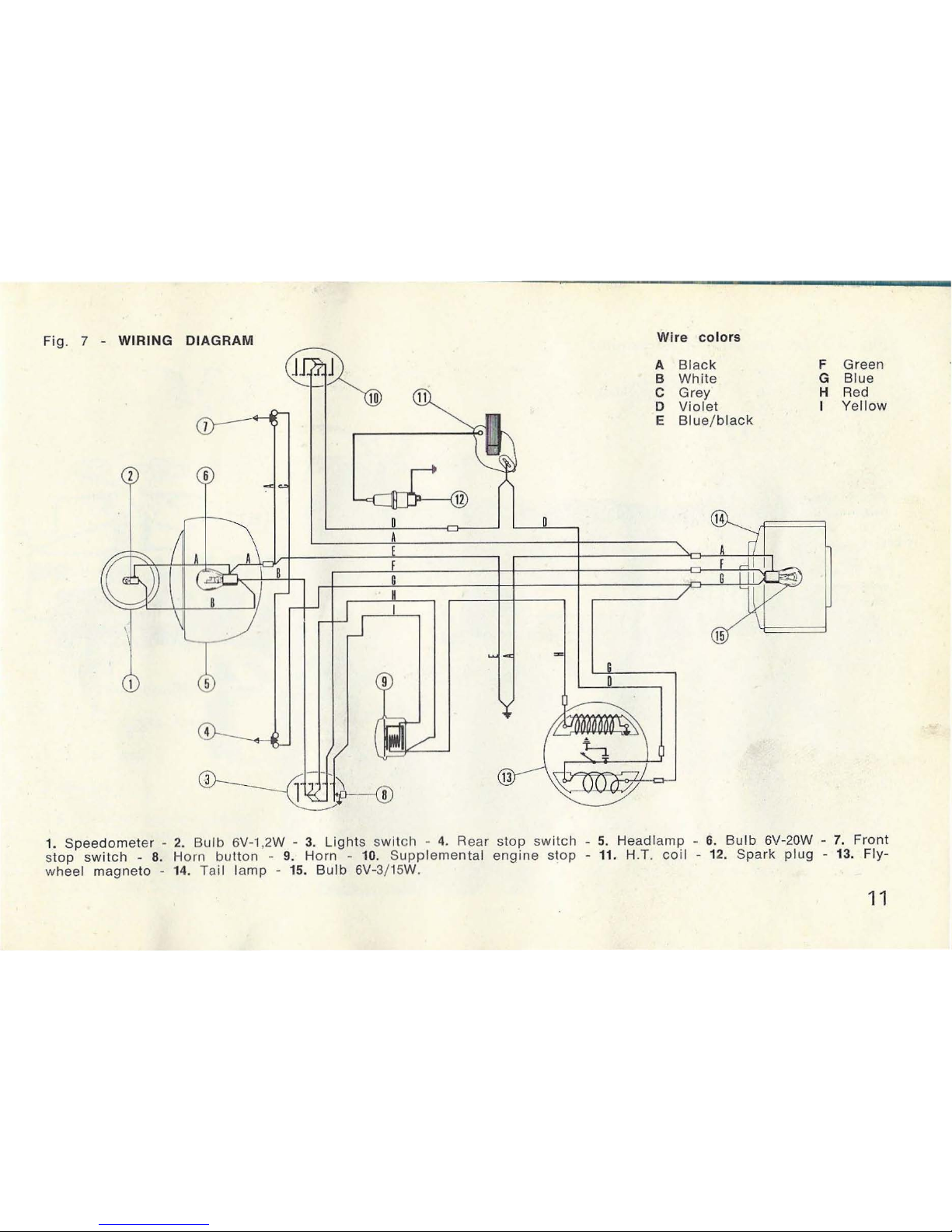
Fig.
7 -
WIRING
DIAGRAM
([1
I
\
\
,.......,
~
1 I
,,,......,
1J_,...'
--~-
~
-
J.
I•
-
10
>
-
D
A
I
-
11
)
-
.....
I
..
..
,ii/
-
'
D
......
-
==
G
0
Wire
colors
A
Black
B
White
C Grey
D
Violet
E
Blue/black
•
(
14
-
-
F Green
G
Blue
H Red
I
Ye
llow
1. Spee
dometer
- 2. Bu
lb
6V-1
,2W - 3.
Lights
switcl1 - 4. Rear
stop
switch
- 5. Head
lamp
- 6·. Bu I b 6V-20W -
7.
Front
s
top
switc
h - 8. H
orn
button
- 9.
Horn
- 10.
Suppleme
ntal
engine
stop
- 11. H.T.
coil
- 12.
Spark
plug
- 13.
Fly-
wheel
magneto
- 14. Tail
lamp
- 15.
Bulb
6V-3/15W.
11
•

\ Fig: 8 -
Engin·e
· and
drive,
scheme
•
• ~ ·-:. .
'(i...
~
..
~
, . .
,• ·\1
t;:~.
~..
...
\
'
.
..
•
1
I
d
2
4
a,
3
c
1.
Engine -2.
Variator:
A)
~entrifugal
weight
of
variator:
B)
Exp
andi
ng
pulley
- 3.
Automatic
c:lutch:
C)
Centi·ifugal
shoes
for
starting:
D)
Centrifugal
shoes
for
drive from
engine:
E)
Expanding
pulley
-
4. R
ear
hub
and
reduction
gear -5.
Rear
wheel
(driving).
12
•

•
Position of controls
1 Rear
brake
lever
•
•
2.
Decompressi
on va
lve
control
3.
Throttle
control
4.
Front
brake
lever
5.
Tank
cap
6.
Peda
1I
. 7.8.
Control
for rear
whe
el
drive
9.
Tool
ki.t
bag lo cated
under
the· saddl
e
Fig. 9
1
• • •
. .
...
- (
..
, . . .
'
.,
.
•
•
13
•
..
 Loading...