

VESDA VLS-XXX Product Manual
Vision Fire & Security
LaserSCANNER
Product Guide
November 10, 2004
Part: 19147


VESDA
®
LaserSCANNER Product Manual
i
Copyright Information
This document is protected by copyright under the laws of Australia and other jurisd ictions t hroughout the world. It must not by any means,
either in whole or part, be reproduced, communicated to the public, adapted, distributed, sold, modified, published except as permitt ed by
any laws or statute or with prior written consent of VFS International Pty Ltd. Copyright© 2004 VFS In ter nat ional Pty Lt d ACN 100 259 381
Disclaimer
The manufacturer reserves the right to change designs or specifications without obligation and without further notice. VESDA,
LaserTEKNIC, LaserPLUS, LaserSCANNER, LaserCOMPACT, LaserFOCUS, VESDAnet, VESDAlink, ASPIRE, ASPIRE2, AutoLearn,
VSM, VConfig, InfoWORKS, PROACTIV, PRECISION, VSC, ADPRO, FastTrace, FastVu, FastScan, Axiom, PRO, Amux and Video
Central are brands and trade marks used under license by the distributor.
FCC Compliance Statement
This equipment has been tested and found to comply with the limits for a Class B digital device, pursuant to part 15 of the FCC Rules.
These limits are designed to provide reasonable protection against harmful interference in a residential installation. This equipment
generates, uses and can radiate radio frequency energy and, if not installed and used in accordance with the instruction, may cause
harmful interference to radio communications. However, there is no guarantee that interference will not occur in a particular installation. If
this equipment does cause harmful interference to rad io o r t ele vi sio n recept ion, the us er is e ncourag ed to t ry to cor rect t he i nt erferen ce by
one or more of the following measures, re-orientate or relocate the receiving antenna, increase the separation between the equipment and
receiver, connect the equipment to a power outlet which is on a different power circuit to the receiver or consult the dealer or an
experienced radio/television technician for help.
General Warning
This VESDA® Aspirating Smoke Detection System must only be installed, configured and used strictly in accordance with the General
Terms and Conditions and System Design Manual available from VFS International Pty Ltd. You acknowledge that you have read and
agree to those terms and conditions. All proper health and safety precautions must be taken during the installation, commissioning and
maintenance of the VESDA
®
Aspirating Smoke Detection System. The system should not be connected to a power source until all the
components have been installed. Proper safet y precautions must be taken during tests and maintenance of the VESDA
®
products when
these are still connected to the power source. Failure to do so or t amperi ng with the electronics insid e the product s can resul t in an electri c
shock causing injury or death and may cause equipment damage. VESDA
®
is not responsible and cannot be held accountable for any
liability that may arise due to improper use of the equipment and/or failure to take proper precautions. Only persons trained through a
VESDA
®
accredited training course can install, test and maintain the system.
Limitation of Liability
This VESDA® Aspirating / Air Sampling Smoke Detection System must only be installed, configured and used strictly in accordance with
the General Terms and Conditions, this manual and the System Design Manual available from VFS Internatio nal Pty Ltd (VFS). You
acknowledge that you have read and agree to those terms and conditions.
You acknowledge that you have been provided with a reasonable opportunity to appraise the VESDA
®
System and have made your own
independent assessment of the fitness or suitabilit y of the VES DA
®
System for your purpose. You acknowledge that you have no t relied on
any oral or written information, representation or advice given by or on behalf of VFS or its representatives.
VFS has no liability to you or any person for incidental or consequential loss, expense or damages including, without limitation, loss of
business, loss of profits or loss of data. You indemnify VFS for any claim, amount or liability brought against VFS in connection with the
VESDA
®
System.
You expressly agree that you assume the entire risk as to the results and performance of the VESDA
®
System resulting from the
configuration of the VESDA
®
System. VFS does not warrant, guarantee or make any representations, either expressly or implied,
regarding the current or future use, or the results of the use, of the VESDA
®
System, with respect to its correctness, accuracy, reliability,
completeness, interworking, functionality, currentness or otherwise resulting from the configuration of the VESDA
®
System.
T o t he full extent permit ted by law, VFS expressly excludes all conditions, warrant ies and liability, whether imposed or implied b y statute or
by rule of law or otherwise, which are not expressly set out in the General Terms and Conditions.
To the extent permitted by law, your sole recourse for any defect of, damage to, or performance standard of the VESDA
®
System will be
under the express warranties the General Terms and Conditions (if applicable) and VFS will in no event be liable to pay any amount or
damages resulting from or in connection with the VESDA
®
System.
To the extent by law that any limitation or exclusion can not apply, the tot al liability of VFS in relation to the VESDA
®
System is limited to:
(i) in the case of services, the cost of having the services supplied again; or
(ii) in the case of goods, the lowest cost of replacing the goods, acquir i ng equivalent goods or having the goods repaired.
To the extent permitted by law , VFS has no liability with respect to damage to or arising out of, or the condition or performance of, the
VESDA
®
System resulting from (i) negligence or improper use, storage, installation, configuration commission, service maintenance or
handling of the VESDA
®
System (where 'improper' includes treatment other than in accordance wit h the VES DA Manu al, these terms and
conditions or the information provided at a training session); (ii) accident , unforeseeable circumst ances or disaster ; (iii) mod ificati ons to the
VESDA
®
System other than in accordance with VFS's instructions; (iv) attachment of or interoperation with features, software or products
not approved by VFS in writing; or (v) where the VESDA
®
System has been serviced by persons not authorized by VFS in writing to
service the VESDA
®
System.
LaserSCANNER Product Manual VESDA
®
ii
VESDA Product Warranty Conditions
VFS International Pty Ltd (VFS) warrants that new VESDA products (excluding consumable items) will conform to its published
specifications and remain in good working order during the warranty period of 24 (twenty four) months from the date an invo ice is issued by
VFS to its distributor.
VFS also warrants that products serviced or repaired by it s service department will remain in good working order for a warranty period of
12 (twelve) months from the date of service. This service or repair warranty is only available on products less than 7 (seven) years old and
only covers those component parts of the products serviced, repaired or replaced.
Should product under warranty not be in good working order, VFS will, at its option, either repair or replace the product or its component
parts at no additional charge.
Spare parts and replacement product, covered under this warranty, will be furnished on an exchange basis and will, at the option of VFS
either be new, equivalent to new or reconditioned. Returned parts and products to VFS become the property of VFS.
This warranty does not cover the repair or damage to the product resulting from or arising out of (i ) negligence or improper use storage,
installation, configuration, commission, servi ce, maintenance or handling of the product (where 'improper' includes treatment other than in
accordance with any manual or instructions for use of the product); (ii) accident, unforeseeable circumstances or disaster; (iii)
modifications to the product other than in accordance with VFS's instructions; (iv) attachment of features or interoperation with features,
software or products not approved by VFS in writing; or (v) where the product has been serviced by persons not authorized by VFS in
writing to service the product.
Document Conventions
The following typographic conventions are used in this document.
The following icons are used in this document
Warranty service may be obtained by:
Notifying Vision Systems and giving full description of fault. Vision Systems will first attempt to rectify fault by supplying replacement
component parts. If rectification is not achieved by component part replacement then distributor is to return fa ulty product to Vision
Systems at Vision Systems cost once Vision Systems has gi ven approval to do so.
Convention Description
Bold Used to denote: emphasis
Used for names of menus, menu options, toolbar buttons
Italics Used to denote: references to other parts of this document or
other documents. Used for the result of an action
Convention Description
Caution: This icon is used to indicate that there is a danger to
equipment. The danger could be loss of data, physical damage,
or permanent corruption of configuration details.
Warning: This icon is used to indicate that there is a da nger of
electric shock. This may lead to death or permanent injury.
Warning: This icon is used to indicate that there is a da nger of
inhaling dangerous substances. This may lead to death or
permanent injury.

VESDA
®
LaserSCANNER Product Manual
iii
Contact Us
www.vesda.com www.adpro.com.au www.millbank.co.uk
Codes and Standards Information
We strongly recommend that this document is read in conjunction with the appropriate local codes and standards for smoke detection
systems and electrical connections. This document contains generic information and some sections may not comply fully with all local
codes and standards. In these cases, the local codes and standards must take precedence.
FM 3611 Hazardous Approval Warning
Exposure to some chemicals may degrade the sealing of relays used on the detector. Relays used on the detecto r are marked "TX2- 5V" or
"G6S-2-5V" or "EC2-5NU".
UL Warning
The fire alarm threshold (signal) that initi ates an evacuat ion proce dure via the Fire Al arm Panel must no t be se t highe r than 0.62 5%/f t. The
detector can send this signal either via the Fire Alarm Panel Output signal or the Pre-alarm output signal.
Safety Label
This VESDA product incorporates a laser device and is classified as a Class 1 laser product that complies with FDA regulations 21 CFR
1040.10. The laser is housed in a sealed detector chamber and contains no serviceable parts. This laser emits invisible light and can be
hazardous if viewed with the naked eye. Under no circumstances should the detector chamber be opened.
Document: 10279_01
This product complies with the following standards
SSL AS1603.8-1996
LPC & VdS GEI 1-048:Jan 1997
UL & CUL UL268 UL268A
FM FM3230-3250 FM3820
FDA 21 CFR 1010.2 21 CFR 1010.3
VESDA AS2211 EN60950
AS/NZS 3548 FCC Class B
EN 50081-1 EN 50130-4
UL and FM Compliancy
All installers must ensure that environments that require UL approved product must have the requirements of a remote display or FACP
connected to the detectors. Failure to do so will void product compliance for UL and FM certif ication th at is st a ted o n the det ect or approval
and rating label.
Approval Certification:
Vision Fire & Security have had this product tested and approve d by UL and FM. This product is fully listed and compliant as long as the
exception in UL268 is adhered to. Please see section 17.5 of UL268, 2003 Edition.
“17.5 A lamp or equivalent means shall be provide d on a spot -type detector head or ba se to identify it as the unit fro m which the alarm was
initiated”.
Exception: The alarm-indicating-means is not required on a detector whose use is restrict ed to a specific control unit that identifies
the individual detector in alarm.
As long as these models are connected to a remote di splay or to a Fire Alarm Control Pan el (FACP) that identifies if the detector is in alarm
then it is a compliant product.
Australia and Asia The Americas Europe & Middle East
Vision Systems
Private Bag 215
495 Blackburn Road
Mount Waverley VIC 3149
Australia
Toll free: 1800 700 203
Tel: +61 (0) 3 9211 7200
Fax: +61 (0) 3 9211 7201
Vision Systems
700 Longwater Drive
Norwell,
Massachusetts, 02061
USA
Toll free: 800 229 4434
Tel: +1 78 740 2223
Fax: +1 78 740 4433
Vision Systems
Vision House, Focus 31,
Mark Road
Hemel Hempstead
Hertforshire HP2 7BW
United Kingdom
Tel: +44 (0) 1442 242 330
Fax: +44 (0) 1442 249 327

LaserSCANNER Product Manual VESDA
®
iv

VESDA
®
LaserSCANNER Product Manual
v
Contents
Scope ...............................................................................................................................................1
Introduction to the LaserSCANNER ..............................................................................................1
Features of the LaserSCANNER ............................................................................................1
Operation of the LaserSCANNER ..................................................................................................1
The Scanning Function ...........................................................................................................3
Scanning ....................................... ............................................................. .........................3
Adaptive scan threshold .....................................................................................................3
The Scanner Valve Test .....................................................................................................4
Sector Factor ...... ... ... .... .......................................... ... .......................................... ... ... .........4
LaserSCANNER Configurations: ............................................................................................5
Display Module ...................................................................................................................6
Display during the scan process ............ .............................................................................9
LCD Programmer .......... ... .......................................... ... .......................................... ... ... ......9
LaserSCANNER Components ..............................................................................................10
LaserSCANNER Product Information .........................................................................................11
Product Specifications ..........................................................................................................11
LaserSCANNER Dimensions ...............................................................................................13
Ratings and Approvals ..........................................................................................................14
Default Settings .....................................................................................................................15
Relays ..................................... ....................................................................... .......................16
Relay Settings and Conditions to Change States .............................................................17
Relay default settings .......................................................................................................18
First alarm sector relays: ...................................................................................................19
General Purpose Input (GPI) Functions ............................................................................20
Mounting the LaserSCANNER .....................................................................................................21
Securing the mounting bracket .............................................................................................21
Mounting the LaserSCANNER detector in Normal Orientation .........................................22
Mounting the LaserSCANNER in the inverted orientation ................................................ 22
Mounting the LaserSCANNER without mounting bracket ........................ ... ... ... .... ... ... ... ... ....22
Recess mounting kit .................................. ... ... ... .... ... .......................................... ... ... .......23
Connecting to the Pipe Network ..................................................................................................24
Inlet Pipes .............................................................................................................................24
Managing the Exhaust Air .....................................................................................................25
Wiring Connections ......................................................................................................................25
The Termination Card ...........................................................................................................25
VESDAnet Terminals ........................................................................................................26
Connections for GPI .........................................................................................................27
Power Source ................................................................................................................................28
Back Up Battery Power .................................................................................................................28
Starting Up .....................................................................................................................................30
Preliminary Systems Check .........................................................................................................30
Maintaining the VESDA LaserSCANNER ....................................................................................31

LaserSCANNER Product Manual VESDA
®
vi
Replacing the chassis/Air Inlet Pipe Manifold .......................................................................32
Internal Wiring for LaserSCANNER ......................................................................................34
Spare Parts ...........................................................................................................................36

VESDA
®
LaserSCANNER Product Manual
1
1.1 Scope
This manual is written to provide you with comprehensive knowledge of the detector.
This manual introduces you to the LaserSCANNER features, technical specifications and gives
an understanding of its components and their function. You will also find instructions on installing,
cabling and powering up the detector.
This manual is for anyone involved with the design, maintenance and purchasing of a VESDA
system. It is assumed that anyone using this manual has knowledge and the appropriate
certification from the local fire and electrical authorities.
1.2 Introduction to the LaserSCANNER
The LaserSCANNER can monitor and individually report on four sectors in the protected area.
The LaserSCANNER is an aspirating smoke detector providing very early warning of fire
conditions by drawing air samples through an air sampling pipe network. The detector chamber
can detect presence of smoke at very low concentrations. The embedded and PC software
complimenting the LaserSCANNER provides a wide range of user defined parameters and
reporting capabilities. The detector easily interfaces with fire warning and fire suppression
release systems, and can be easily integrated into a building management system.
Features of the LaserSCANNER
The LaserSCANNER features make it a versatile smoke detection product:
• Wide sensitivity range 0.005% obs/m to 20.0% obs/m (0.0015% obs/ft. to 6.24% obs/ft.)
• Each detector can cover an area of up to 2,0 0 0 m
2
(20,000 sq. ft.)
• Four programmable alarm thresholds (Alert, Action, Fire 1 and Fire 2)
• AutoLearn feature
• Four pipe inlets
• Individual pipe flow monitoring
• Scans individual sectors once smoke has been detected
• Replaceable air filter cartridge
• Option for inverted mounting
• Recessed mounting option
• Modular to meet site specific requirements
• Modular Display Module and LCD Programmer
• Programmable relays (option for 7 or 12 relays available)
• High efficiency aspirator
• Programmable General Purpose Input (GPI) to invoke operational modes
• PC programming and monitoring
• Multilingual displays
• Event Log for up to 18,000 events
1.3 Operation of the LaserSCANNER
An air sampling pipe network with sampling holes at appropriate spacing collects air samples
from a protected area.
An integrated Aspirator draws air in the sampling pipes through a Pipe Inlet Manifold (up to four
pipes can be connected to a LaserSCANNER detector). For further information on air sampling
pipe network please see the Pipe Network Design and Installation Manuals.
LaserSCANNER Product Manual VESDA
®
2
Each pipe inlet in the manifold has a valve that can open or close the flow of air to the pipe. The
scan function controls the opening and closing of the valves to detect the smoke carrying pipe.
See The Scanning Function on page 3 for further information.
Some of the sampled air flows to the dual stage air filter. The first stage filtration removes dust
and dirt from the sampled air and a small percentage of this air then flows to the laser detector
chamber for detection smoke.
Any smoke detected in the laser detection chamber is signaled to the main processor card . If the
presence of detected smoke is higher than the set thresholds it will be reported as an alert,
action, fire 1 or fire 2 Alarm depending upon the set alarm thr esholds. The second stage filtration
further filters the air to make it ultra clean air. The ultra clean air is used to protect the optical
surfaces in the laser detector chamber.
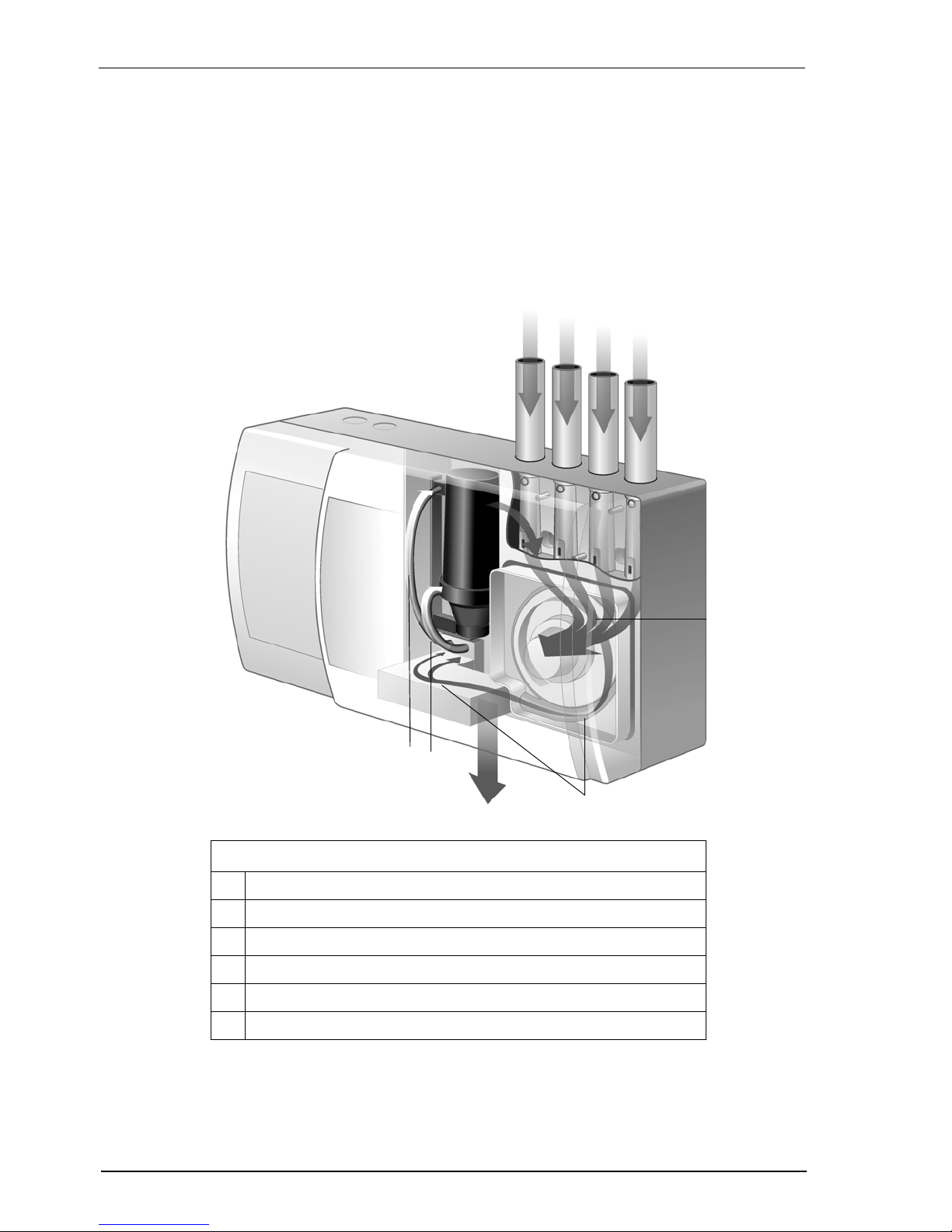
Figure 1 - Operation and internal air flow of a LaserSCANNER
A
B
C
D
E
F
Legend
A Air inlets from pipe networks
B Air is drawn into the aspirator
C Some air is filtered and:
D -flows into the chamber for testing
E -is filtered a second time, then used to flush the chamber with ultra clean air
F All air is then exhausted

VESDA
®
LaserSCANNER Product Manual
3
The Scanning Function
The LaserSCANNER is designed to sample air from different sectors and to identify through a
scanning process the sector reporting presence of smoke.
Scanning
During normal operation the scanner valves remain open and the LaserSCANNER draws air
from all the pipes. When smoke is detected at a higher level than the scan threshold, for a period
exceeding the configured scan delay (0 to 10 seconds), the detector performs a fa st scan. During
the fast scan operation the LaserSCANNER samples air from e a ch sector (pipe) separately by
controlling the scanner valves in the inlet manifold. The fast scan sequence for each pipe is
approximately 4 seconds.
The sector reporting the highest level of smoke above the alert threshold is designated as the
first alarm sector. The display modules assigned to the detector reports this by illuminating the
first alarm and alert LEDs, and displaying the corresponding pipe number on the numeric screen.
Having identified the first alarm sector, the LaserSCANNER performs a slow scan using
intelligent sequencing. The sector with the highest level of smoke (the first alarm sector) is
scanned first. Each of the other sectors is scanned one at a time. Intelligent sequencing scans
the first alarm sector in every alternate scan (e.g. if all the pipes are in use and pipe 1
corresponds to the first alarm sector then intelligent sequencing will scan Pipe
1,2,1,3,1,4,1,2......). The time spent sampling air in each sector depends upon the configured
sector time.
Adaptive scan threshold
The scan threshold is the configured threshold at which the detector co mmences scan ning once
smoke has been detected at the threshold. The LaserSCANNER performs an adaptive scan
process to automatically set scan thresholds at the optimized level. The adaptive scan threshold
process is explained below:
• Typically separate scan thresholds are set for day and night periods.
• Scan thresholds are initially set to the lowest day or night alert threshold divided by the
number of pipes. If the threshold is set by AutoLEARN, the day or Night Alert Threshold is
divided by 2.
• The scan thresholds are then adapted automatically to eliminate unnecessary and
excessive scan cycles.
- Adapting the scan threshold u pwards - When the detected smok e level is lower than
the configured Alert Threshold, the scan threshold increases upwards by 0.005% obs/m
0.0016% obs/ft.) with every fast scan cycle. It will continue to do so until the scan threshold
is above the ambient smoke level or it equals the Alert Threshold. The scan threshold
cannot exceed the Alert Threshold
- Adapting the scan threshold downward s - At every changeover time (from Day to
night and from night to day) the detector determines if it is necessary to adapt the scan
threshold downwards. Thus, if the scan threshold has been adjusted upwards, then in the
following 24 hour period the detector begins a process of gradually lowering the scan
threshold downwards to an optimum setting. The detector maintains a record of the
maximum smoke readings measured in each day (or night) period. At the start of the next
day (or night) period the scan threshold is automatically scaled downwards by calculating
the difference between the current scan threshold and the ma xim um smo ke re adin g for the
previous day (or night) period.

LaserSCANNER Product Manual VESDA
®
4
The Scanner Valve Test
The VESDA LaserSCANNER performs a scanner valve test when first powered up. Thereafter a
valve test is performed every alternate T u esday at 12:00 hours. Duri ng the va lve test each val ve
is individually closed and opened to ensure its proper functioning. Any improper functioning is
reported as a fault (refer to the VESDA Tro ubleshooting Guide for fault descriptions and
troubleshooting). It is possible to simulate a valve scan test by pressing the Silence/Scan button
on the Display Module for two seconds, or selectin g th e sca n te st op tion un de r the dia g no stic s
menu on the LCD programmer or the device menu on the PC software.
Sector Factor
By setting appropriate sector factors it is possible to set differen t alarm thr esholds for each o f the
four sectors. The detector uses the sector factor to automatically calculate the alarm thresholds
appropriate for each sector based on the configured alarm thresholds. These are multiplied by
the sector factor to set the sector alarm thresholds.
Guidelines for setting sector factors:
• Sector factors range between 0.5 and 2.0
• Where more sensitive protection is desired for a sector (for example a critical server room
where there are relatively more sampling holes and re str icted access), set the se cto r factor
at less than 1.0
• Where less sensitive protection is desired for a sector (for example where there is a risk th at
a particular local process will generate nuisance alarms), set the sector factor at greater
than 1.0
• As a general rule, the difference between all pipes should not be greater than 1
Sector factors are generally optimized after a detector has been operational for a period and
sufficient historical data has been g athered in the event log to assist the decision. However, if it is
required to pre-determine the appropriate setting for sector factor the fo llowing methodo logy can
be used:
• Use ASPIRE Pipe Modelling Software to model the intended pipe layout
• Determine the appropriate fire sensitivity required for each sector to achieve the desired
hole sensitivity in each sector
• Select an appropriate median setting for the Fire 1 thre shold to be configured in th e detector
and calculate the appropriate sector factor which, when multiplied by the configured Fire 1
threshold, will give the desired fire sensitivity for each pipe
• Record the desired Fire1 threshold setting and sector factor setting for configuration into the
detector at commissioning.
VESDA
®
LaserSCANNER Product Manual
5
LaserSCANNER Configurations:
One or more devices can be integrated with the LaserSCANNER detector. These are normally
configured at the factory prior to shipping, but can also be installed at a later time. The st andard
LaserSCANNER comes with 7 relays or in an optional 12 relay versio n. The modules that ca n be
integrated are:
• Display Module
• LCD Programmer Module
• Fire and OK LEDs (FOK) Module
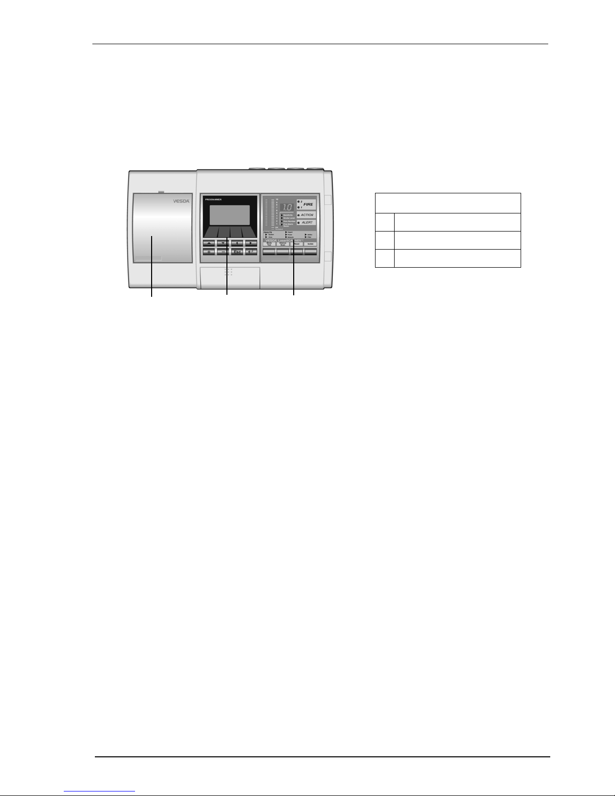
Figure 2 - VLS-214 VESDA LaserSCANNER with 7 relays, blank plate, LCD
Programmer and Display Module
Legend
A Blank Plate
B LCD Programmer
C LaserSCANNER Display Unit
A
B
C
LaserSCANNER Product Manual VESDA
®
6
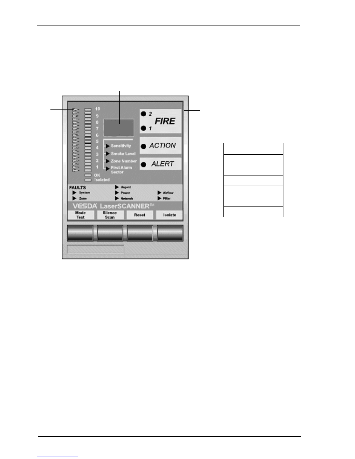
Display Module
The LaserSCANNER Display Module is mounted either on the detector front cover or at a remote
location in a remote mounting box or a 19” subrack. It provides a visual representation of the
smoke levels and the four alarm stages for the a ssign ed detector. An array of fault LEDs light up
in different configurations to report Urgent, Minor, Zone and System faults. Up to 20 Display
Modules can be assigned to one detector, however the Display Module can be configured to
report the status of only one detector at a time.
Figure 3 - LaserSCANNER display module
OK LED
The OK LED stays lit during normal operation indicating the unit is functioning
normally. When this LED is off a warning beep sounds, indicating a Fault
condition is active.
Isolate LED
This LED is lit when the detector is Isolated and relays are de-activated
disabling alarm outputs of the detector. The display can be programmed to
beep every 60 seconds.
B
A
C
D
E
F
Legend
A Threshold Indicators
B Bar graph
C Numerical Display
D Alarm Level LEDs
E Fault LEDs
F Push Button Keys
VESDA
®
LaserSCANNER Product Manual
7
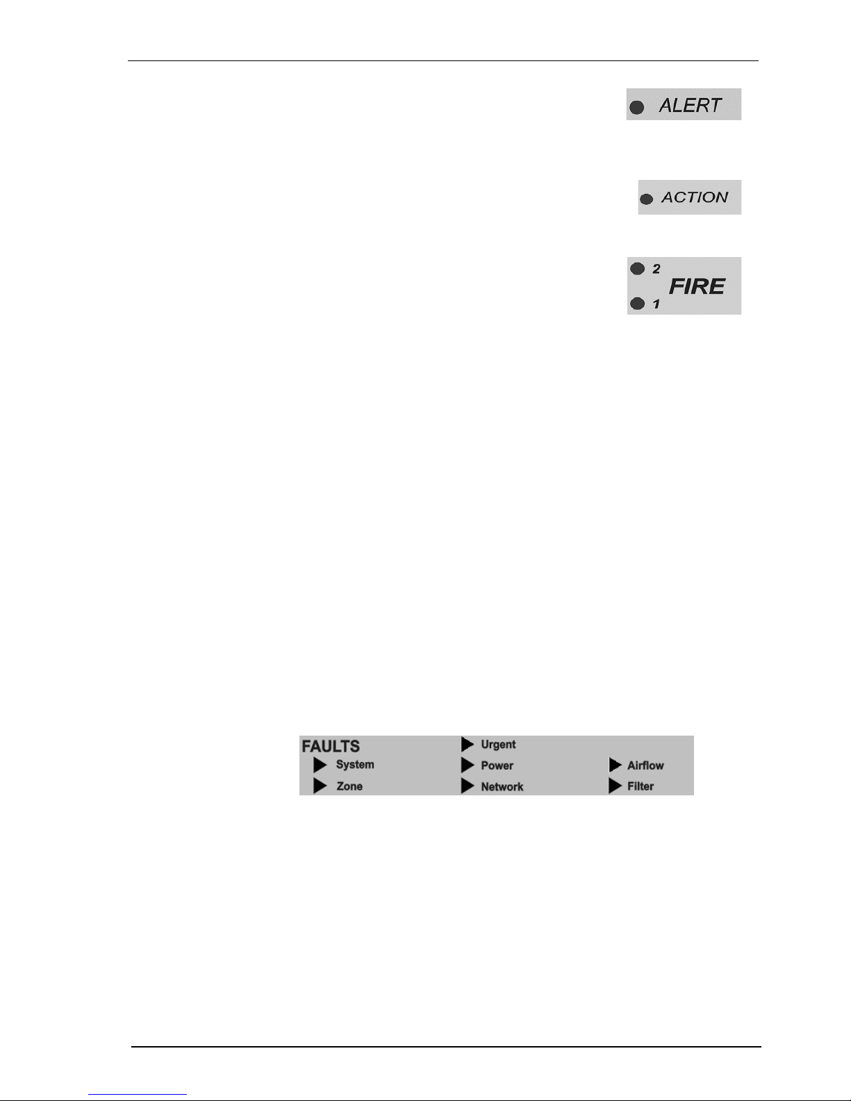
Alarm Levels
ALERT: When lit this LED indicates that the smoke
level is above the alert threshold. This means the
detector has identified very early stages of a fire
condition and/or that the smoke level in the area is
above normal.
ACTION: When lit this LED indicates that the detected
smoke level has passed the threshold value fixed for
Action, but is not intended to initiate a general fire alarm
response procedure.
FIRE 1: When lit this LED indicates that the detected
smoke level is above the threshold value set to initiate
a general fire alarm response procedure. This
indicates a fire may be imminent or is in progress.
When interfaced with a Fire Alarm Control Panel
(FACP) it can generate an automatic fire alarm.
FIRE 2: When lit this LED indicates a fire is in progress. The detector can be
interfaced with an FACP to activate automatic suppression systems and
evacuation procedures.
Bar graph
The Bar graph is a 20 step indicator where each indicator represents an
increase in the detected level of smoke, relative to the preset fire alarm level.
Threshold
Indicators
The illuminated LEDs represent visual settings for ALERT , ACTION, and FIRE
1 alarm levels. The FIRE 1 indicator is always at the top.
Fault LEDs
The Fault LEDs illuminate to indicate:
URGENT: A serious fault requiring immediate attention
SYSTEM: A fault affecting the network to which the Display module is
connected
ZONE: A fault in the VESDA Zone monitored by the Display module
POWER: A fault in the power supply if the GPI function is used
NETWORK: A communications fault on VESDAnet
AIRFLOW: Higher or lower than acceptable levels of air flow through the inlet
pipe(s)
FILTER: The air filter requires changing
 Loading...