

VESDA VLQ-100 Product Manual

VESDA VLQ
Product Guide
VLQ-100
February 2014
Document: 26104_03
Part Number: 30320


VESDA by Xtralis VESDAVLQ Product Guide
www.xtralis.com i
Intellectual Property and Copyright
This document includes registered and unregistered trademarks. All trademarks displayed are the trademarks of
their respective owners. Your use of this document does not constitute or create a licence or any other right to use
the name and/or trademark and/or label.
This document is subject to copyright owned by Xtralis AG (“Xtralis”). You agree not to copy, communicate to the
public, adapt, distribute, transfer, sell, modify or publish any contents of this document without the express prior
written consent of Xtralis.
Disclaimer
The contents of this document is provided on an “as is” basis. No representation or warranty (either express or
implied) is made as to the completeness, accuracy or reliability of the contents of this document. The manufacturer
reserves the right to change designs or specifications without obligation and without further notice. Except as
otherwise provided, all warranties, express or implied, including without limitation any implied warranties of
merchantability and fitness for a particular purpose are expressly excluded.
General Warning
This product must only be installed, configured and used strictly in accordance with the General Terms and
Conditions, User Manual and product documents available from Xtralis. All proper health and safety precautions
must be taken during the installation, commissioning and maintenance of the product. The system should not be
connected to a power source until all the components have been installed. Proper safety precautions must be taken
during tests and maintenance of the products when these are still connected to the power source. Failure to do so
or tampering with the electronics inside the products can result in an electric shock causing injury or death and may
cause equipment damage. Xtralis is not responsible and cannot be held accountable for any liability that may arise
due to improper use of the equipment and/or failure to take proper precautions. Only persons trained through an
Xtralis accredited training course can install, test and maintain the system.
Liability
You agree to install, configure and use the products strictly in accordance with the User Manual and product
documents available from Xtralis.
Xtralis is not liable to you or any other person for incidental, indirect, or consequential loss, expense or damages of
any kind including without limitation, loss of business, loss of profits or loss of data arising out of your use of the
products. Without limiting this general disclaimer the following specific warnings and disclaimers also apply:
Fitness for Purpose
You agree that you have been provided with a reasonable opportunity to appraise the products and have made
your own independent assessment of the fitness or suitability of the products for your purpose. You acknowledge
that you have not relied on any oral or written information, representation or advice given by or on behalf of Xtralis
or its representatives.
Total Liability
To the fullest extent permitted by law that any limitation or exclusion cannot apply, the total liability of Xtralis in
relation to the products is limited to:
1. in the case of services, the cost of having the services supplied again; or
2. in the case of goods, the lowest cost of replacing the goods, acquiring equivalent goods or having the goods
repaired.
Indemnification
You agree to fully indemnify and hold Xtralis harmless for any claim, cost, demand or damage (including legal costs
on a full indemnity basis) incurred or which may be incurred arising from your use of the products.
Miscellaneous
If any provision outlined above is found to be invalid or unenforceable by a court of law, such invalidity or
unenforceability will not affect the remainder which will continue in full force and effect. All rights not expressly
granted are reserved.
VESDAVLQ Product Guide VESDA by Xtralis
ii www.xtralis.com
Scope
The VESDA VLQ Product Guide provides a comprehensive description of the VLQdetector.
This guide introduces the VESDA VLQ features, technical specifications and gives an understanding of its
components and their function. You will also find instructions on installing, cabling and powering up the
detector.
This guide is for anyone involved with the design, maintenance and purchasing of a VESDA VLQ system. It is
assumed that anyone using this product has the knowledge and appropriate certification from local fire and
electrical authorities.
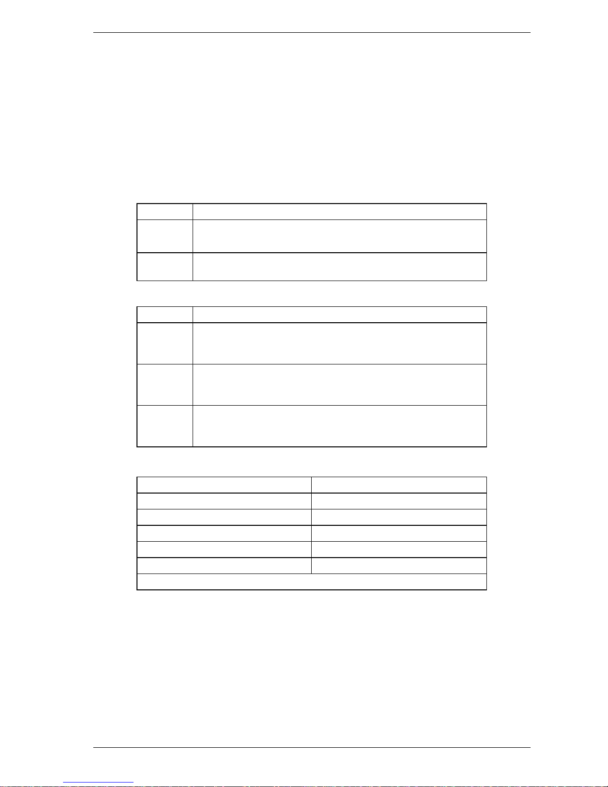
Document Conventions
The following typographic conventions are used in this document:
Convention Description
Bold Used to denote: emphasis.
Used for names of menus, menu options, toolbar buttons
Italics Used to denote: references to other parts of this document or other
documents. Used for the result of an action.
The following icons are used in this document:
Convention Description
Caution: This icon is used to indicate that there is a danger to
equipment. The danger could be loss of data, physical damage, or
permanent corruption of configuration details.
Warning: This icon is used to indicate that there is a danger of electric
shock. This may lead to death or permanent injury.
Warning: This icon is used to indicate that there is a danger of inhaling
dangerous substances. This may lead to death or permanent injury.
Contact Us
UKand Europe +44 1442 242 330
D-A-CH +49 431 23284 1
The Americas +1 781 740 2223
Middle East +962 6 588 5622
Asia +86 21 5240 0077
Australia and New Zealand +61 3 9936 7000
www.xtralis.com
VESDA by Xtralis VESDAVLQ Product Guide
www.xtralis.com iii
Codes and Standards Information for Air Sampling Smoke Detection
We strongly recommend that this document is read in conjunction with the appropriate local codes and standards
for smoke detection and electrical connections. This document contains generic product information and some
sections may not comply with all local codes and standards. In these cases, the local codes and standards must
take precedence. The information below was correct at time of printing but may now be out of date, check with your
local codes, standards and listings for the current restrictions.
FCC Compliance Statement
This equipment has been tested and found to comply with the limits for a Class B digital device, pursuant to part 15
of the FCC Rules. These limits are designed to provide reasonable protection against harmful interference in a
residential installation. This equipment generates, uses and can radiate radio frequency energy and, if not installed
and used in accordance with the instruction, may cause harmful interference to radio communications. However,
there is no guarantee that interference will not occur in a particular installation. If this equipment does cause
harmful interference to radio or television reception, the user is encouraged to try to correct the interference by one
or more of the following measures; re-orientate or relocate the receiving antenna, increase the separation between
the equipment and receiver, connect the equipment to a power outlet which is on a different power circuit to the
receiver or consult the dealer or an experienced radio/television technician for help.
FDA
This Xtralis product incorporates a laser device and is classified as a Class 1 laser product that complies with FDA
regulations 21 CFR 1040.10. The laser is housed in a sealed detector chamber and contains no serviceable parts.
The laser emits invisible light and can be hazardous if viewed with the naked eye. Under no circumstances should
the detector chamber be opened.
The laser chamber is identified by the label shown below:
DANGER
DO NOT OPEN
NO SERVICEABLE
PARTS
Laser Radiation when Open
AVOID DIRECT EXPOSURE TO BEAM
NE PAS OUVRIR
DISPOSITIFS/PIECES
NON ECHANGEABLES
Rayonnement Laser en cas d’ouverture
EVITEZ TOUTE EXPOSITION DIRECTEAU FAISCEAU
Product Listings
l UL
l ULC
l VNIPPO
l EN 54-20 and other agencies (pending)
Document: 26104_03
Part Number: 30320

VESDAVLQ Product Guide VESDA by Xtralis
iv www.xtralis.com
This page is intentionally left blank.

VESDA by Xtralis VESDAVLQ Product Guide
www.xtralis.com 1
Table of Contents
1 Introduction 3
1.1 Features 4
2 Product Information 5
2.1 How it Works 5
2.2 Detector Overview 6
2.3 Specifications 9
2.4 Dimensions 10
3 Air Sampling Pipe Network 11
3.1 Installation Considerations 11
3.2 Pipe Inlets 11
3.3 Exhaust Air 11
3.4 Air Sampling Configurations 12
4 Installation 15
4.1 Mounting 16
4.2 Wiring 22
4.3 Specify Backup Battery for Power Supply 25
4.4 Installation Checklist 26
4.5 Powering Up 27
4.6 Preliminary System Check 27
5 Configuration 29
5.1 Logging on using the Display Panel 29
5.2 Setting the time using the Display Panel 29
5.3 DIP Switch Configuration 30
6 Commissioning 31
6.1 AutoLearn Smoke 31
6.2 Commissioning Smoke Test 31
7 Xtralis QSCSoftware 33
7.1 Installation 33
7.2 Functions 33
7.3 Configuration 34
7.4 Device Information 35
8 Maintenance 37
8.1 Replacing the Filter 37
9 Troubleshooting 41
9.1 Fault Codes 41

VESDAVLQ Product Guide VESDA by Xtralis
2 www.xtralis.com
This page is intentionally left blank.
VESDA by Xtralis VESDAVLQ Product Guide
www.xtralis.com 3
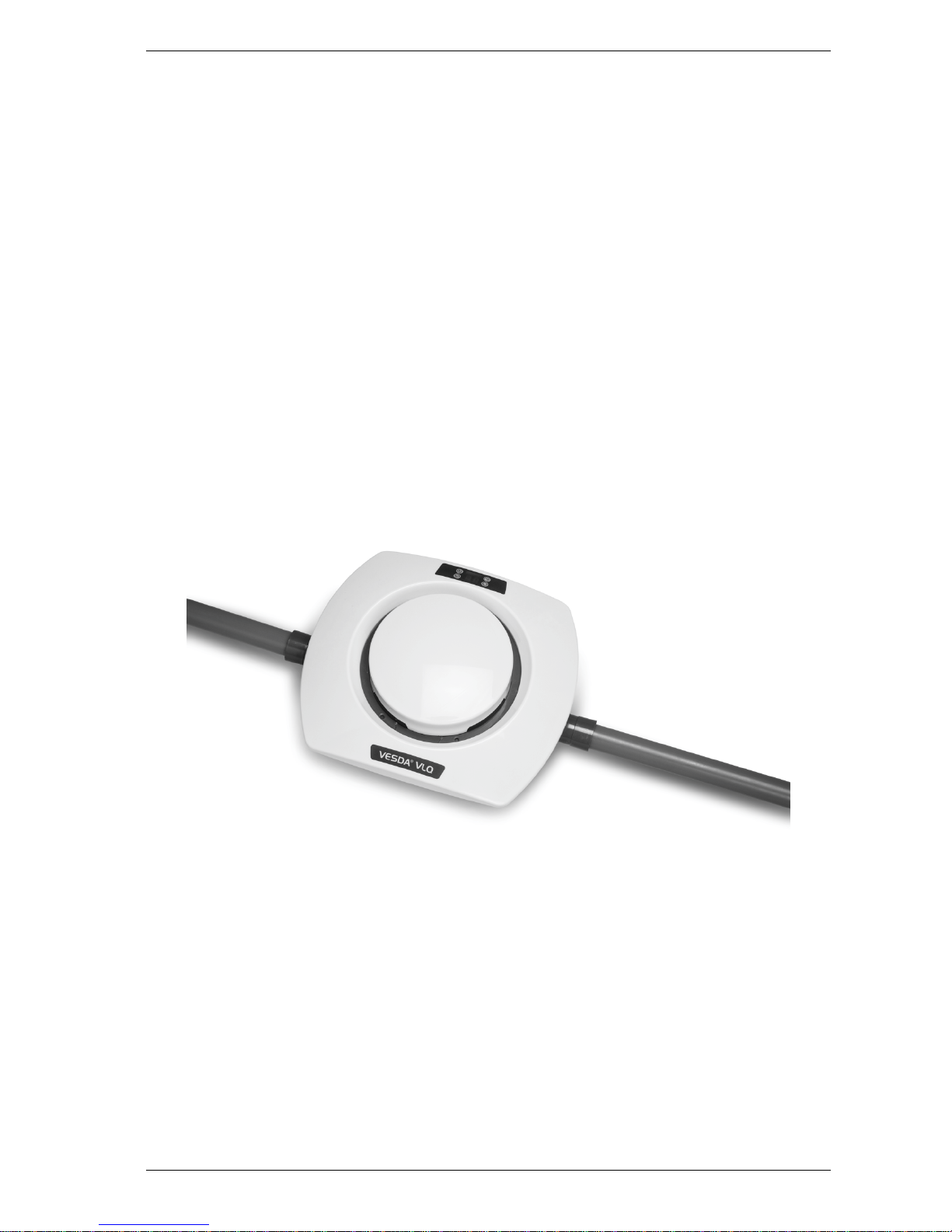
1 Introduction
The VESDA VLQ is an Aspirating Smoke Detector (ASD) that provides very early warning of fire conditions
by drawing air samples through sampling holes located in an air sampling pipe network.
The VESDA VLQ detector is specifically designed to cater for small areas up to 100m² (1000ft²). VESDA
VLQ is suited to several applications, including but not limited to:
l Telecommunications land line remote offices
l Base station controllers (BSC)
l Base transceiver stations (BTS)
l Server rooms
l Datacenter containers
l IT/equipment cabinets
l Controlled environmental vaults (CEV)
l Semi-conductor tools
l Modular laboratories
l Anechoic chambers
l Flight simulators
l Generator enclosures
l Signaling huts
l Pump houses
l Ammunitions holding areas
l Hyperbaric chambers
l Barracks self-contained units
Connection to the detector using Xtralis QSC software is available via the USB interface.
Figure 1-1: VESDA VLQ
The detector contains dry-contact relays which allow connectivity to fire warning and fire suppression release
systems, and integration into a building management system (BMS).

VESDAVLQ Product Guide VESDA by Xtralis
4 www.xtralis.com
1.1 Features
The VESDA VLQ detector provides the following features:
l Laser-based absolute smoke detection
l Clean air barriers for optics protection
l Up to 100 m² (1000 ft²)coverage
l Up to 2 x 6m (2 x 20ft) pipes (straight), up to 2 x 9m (2 x 30ft) pipes (branched)
l 2 or 4 VEWFD / EWFD (NFPA76), or 2 or 4 Class A / Class B (EN 54-20) sample holes
l Metric/Imperial pipe inlets
l Pre-alarm, Alarm and Fault Relays
l 5 LEDs: Pre-alarm, Fire-alarm, Fault, Power, Filter replacement
l Monitored on-board filter
l AutoLearn Smoke
l General Purpose Input (GPI)
l IP30 enclosure
l Xtralis QSC software support
l USB for direct PC connection
l Event log
l Low power consumption
VESDA by Xtralis VESDAVLQ Product Guide
www.xtralis.com 5
2 Product Information
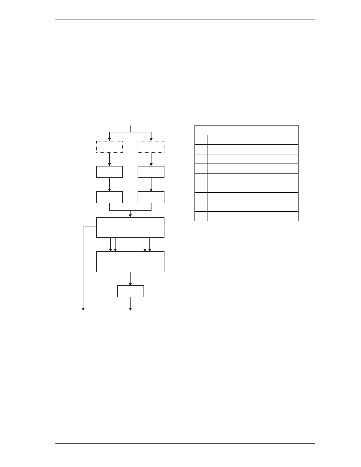
2.1 How it Works
The VESDA VLQ detector continually samples air from the protected environment via two pipe inlets for the
sampling pipes on each side of the pipe inlets (A1, A2). Upon entering the detector, the air passes through
respective inlet manifolds (B1, B2) and the aspirators (C1, C2). The sampled air then enters the filter (D)
where the majority is exhausted out through filter exhaust (I2) and a portion from each inlet is separated into
two pathways, one pathway enters as clean air (E1,E2) and the other pathway enters as sampled air (F1,F2)
into the detection chamber (G). Sampled air is used for smoke detection and the clean air used for optics
protection. After smoke detection the air is exhausted out of the chamber exhaust (I1). Flow measurement is
performed at the chamber exhaust (H).
D
G
E1
F2
B1
A1
B2
A2
C1 C2
F1 E2
H
Legend
A PipeInlets
B Manifolds
C Aspirators
D Filter
E Clean Air
F Sample Air
G Detection Chamber
H Flow Sensor
I Exhaust
Figure 2-1: Air Path
VESDAVLQ Product Guide VESDA by Xtralis
6 www.xtralis.com
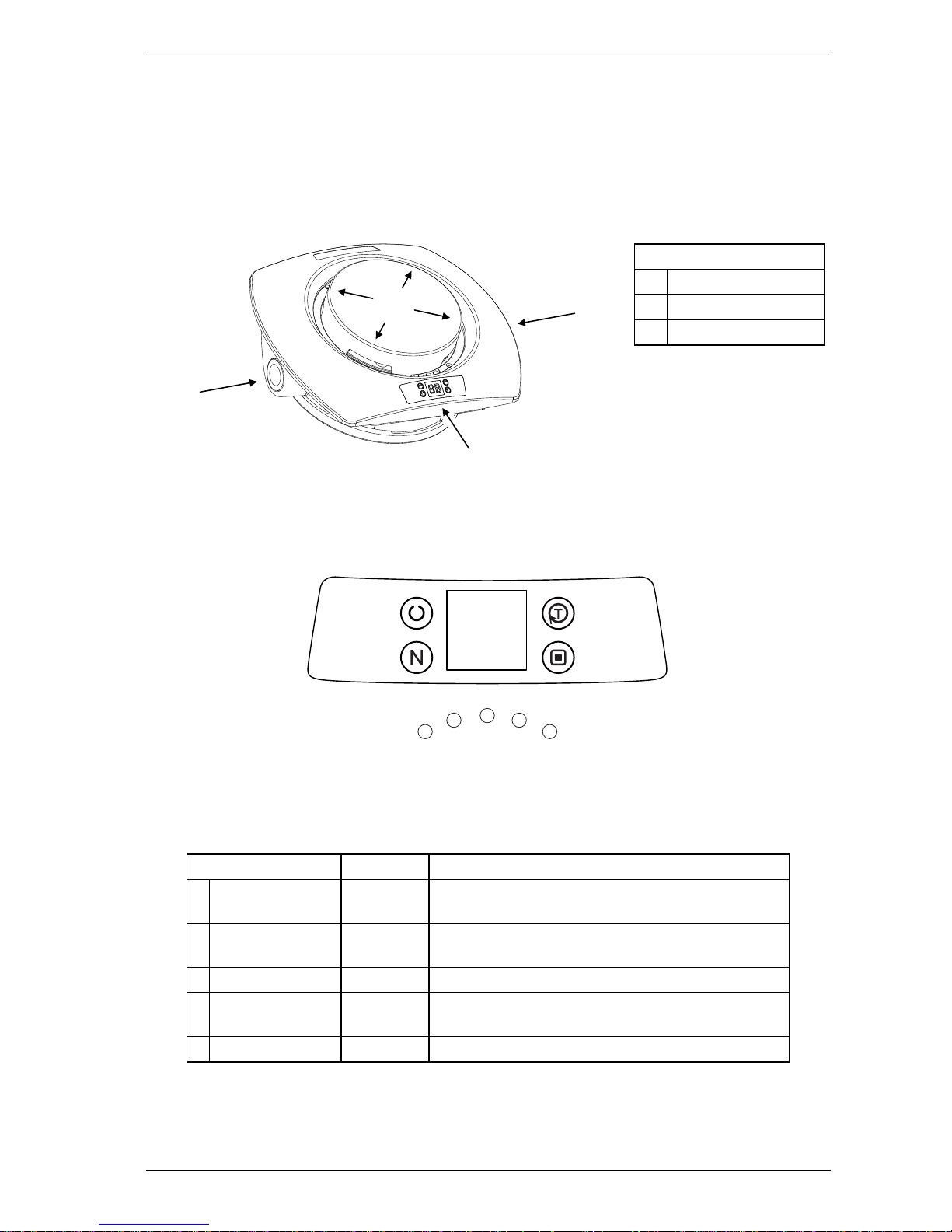
2.2 Detector Overview
The VESDA VLQdetector is a lightweight unit designed to be ceiling or wall mounted and operates with a
simple sampling pipe network. The detector unit features two sampling pipe inlets, unobtrusive exhaust vents,
a simple control panel and display, and a buzzer to provide audio notifications.
AUSBport, described below in Section 2.2.3, provides the ability to interface with a computer, which allows
configuration with the Xtralis QSC software. Configuration DIPswitches and wiring terminals are located
beneath the detector and are accessible by removing the detector base..
A
A
B
C
Legend
A Sampling Pipe Inlets
B ExhaustVents
C Front Panel
Figure 2-2: VESDA VLQ Detector Overview
2.2.1 Front Panel
The VESDA VLQ front panel contains a series of indicators and buttons. These are described below.
88
A
B
C
D
E
Figure 2-3: VESDA VLQ Front Panel and Status LEDs
Indicators
The VESDA VLQ detector provides information via a series of Status LEDs.
LED Color Description
A Power Green The Power LED illuminates when the detector is
powered up.
B Filter Replacement Yellow The Filter Replacement LEDis lit when the filter is due
for replacement.
C Fault Yellow The Fault LED is lit when a fault condition is detected.
D Pre-Alarm Red The Pre-Alarm LED is lit when the Pre-Alarm threshold
is reached.
E Fire-Alarm Red The Fire LED is lit when the Fire threshold is reached.
Table2-1: LEDIndicators
VESDA by Xtralis VESDAVLQ Product Guide
www.xtralis.com 7
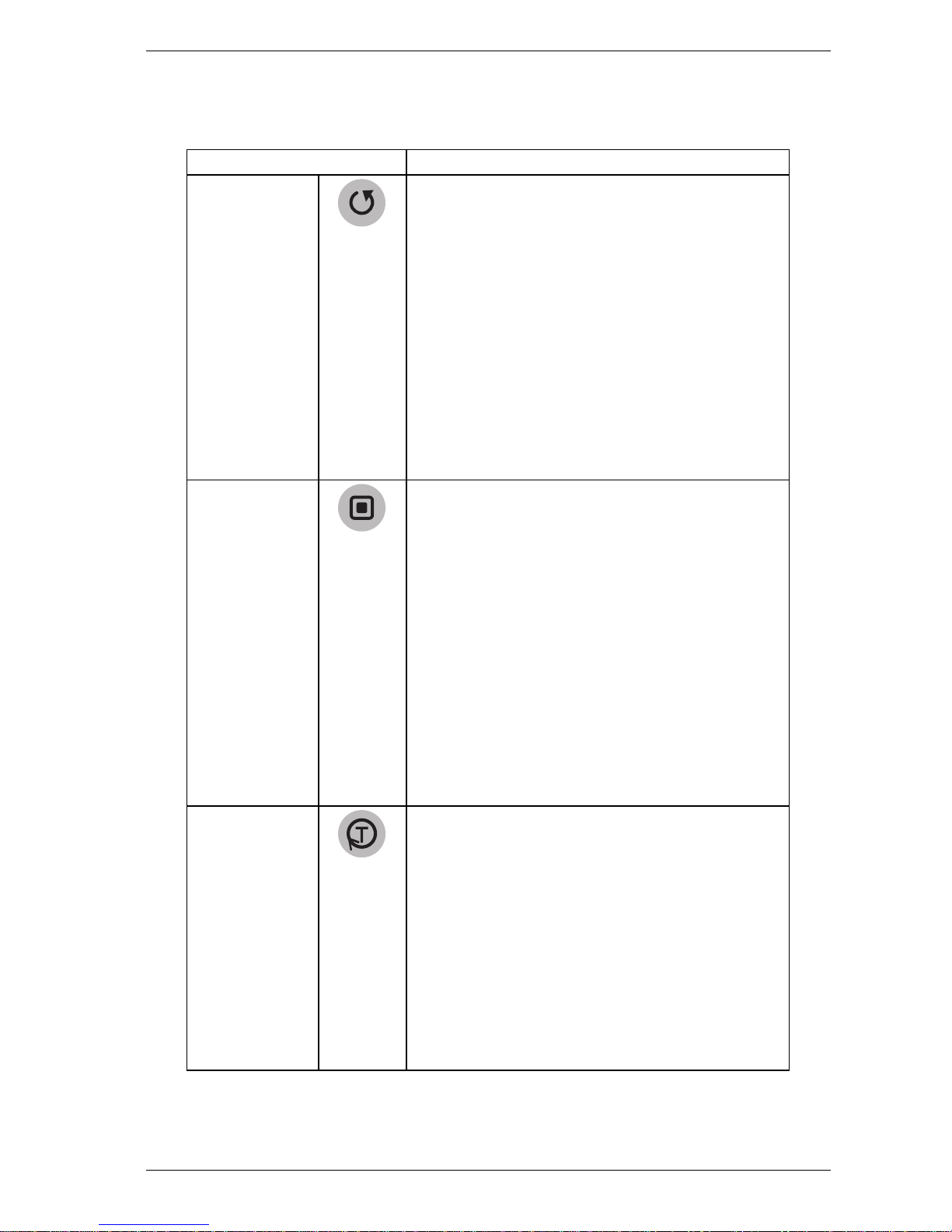
Buttons
The VESDA VLQ detector provides accessibility to a range of functions via a set of control buttons.
Button Description
Reset / Silence Resetting the detector unlatches all latched alarms and
faults, returns relays to their normal state and clears the
active event list.
Silencing silences the buzzer for the current fault.
l To reset the detector, press this button once, 'rs' is
displayed on the panel.
l To silence the buzzer, press and hold this button till
"SI" is displayed on the panel (5 to 10 seconds). SI is
displayed alternately with the highest priority fault
code. The buzzer will remain silent unless another fault
is reported.
l To take detector out of Silence mode, press this button
once while detector is displaying "SI".
While the filter is removed, pressing the Reset / Silence
button once will reset the filter use percentage value.
Disable / Standby Disabling the detector disables all relay outputs with the
exception of the fault relay. The aspirator remains active.
Standby shuts down the aspirator and puts the detector
standby mode. There is no smoke detection during standby,
and the fault relay is activated.
l To disable the detector, press this button once.
l To re-enable the unit, press the button while "db" is
displayed on the panel.
l To place the detector in standby mode, press and hold
this button until "Sb" is displayed on the panel (5 to 10
seconds). To take detector out of standby mode, push
and hold this button when "Sb" is displayed on the
panel (5 to 10 seconds).
Note: You must be logged on to the detector through
front panel to use this button. Refer to Section 5.1
for further information.
Test Two Test modes are available:
l Lamp and Buzzer Test: Press this button to ensure
that all LEDs,display segments and buzzer operate
correctly. "Lt" is displayed momentarily when the
button is pressed.
l Alarm and Fault Test:Press and hold this button until
"At" is displayed on the front panel (5 to 10 seconds). It
activates alarm and fault relays. To stop the test press
and hold this button when "At" is displayed on the
panel.
Note: You must be logged on to the detector through
front panel to use this button. Refer to Section 5.1
for further information.
Table2-2: Control Buttons
VESDAVLQ Product Guide VESDA by Xtralis
8 www.xtralis.com
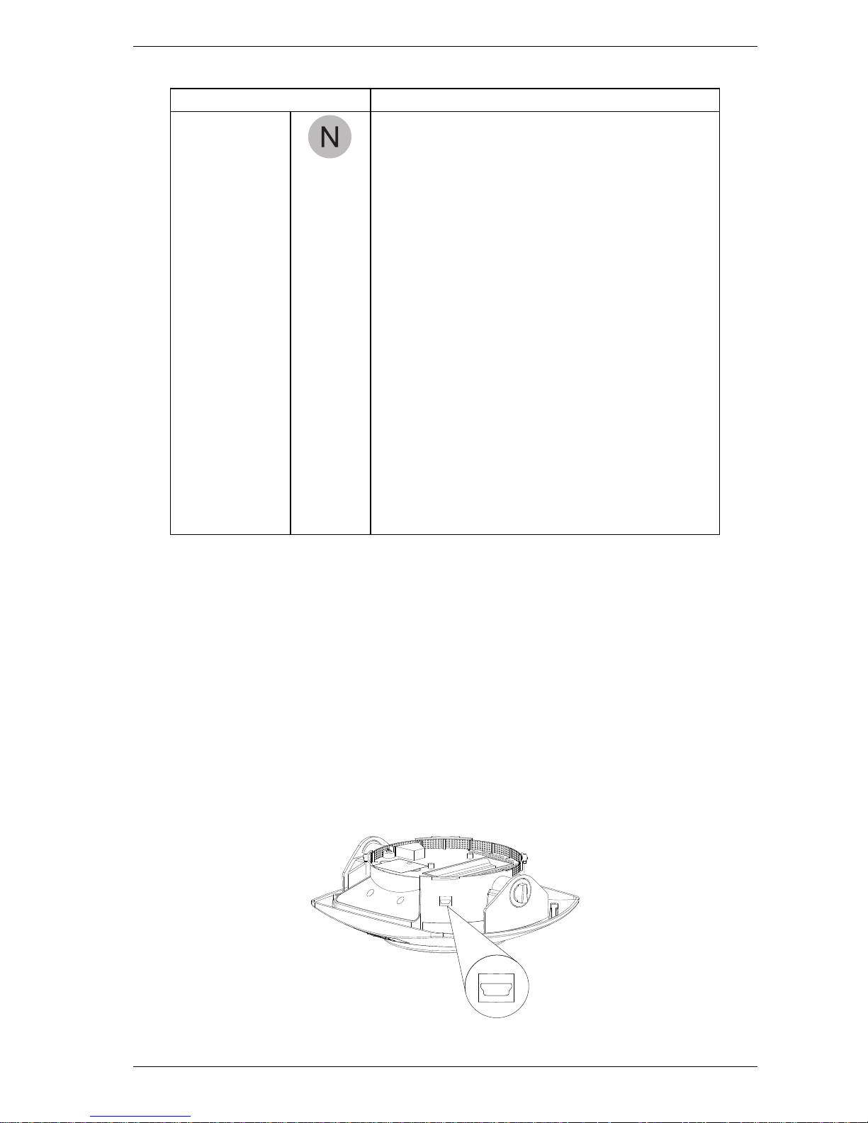
Button Description
Normalize Airflow /
AutoLearn Smoke
Airflow Normalization sets the reference point for airflow
thresholds based on ambient operating conditions.
AutoLearn Smoke sets the alarm thresholds based on the
environmental conditions.
l Press this button once to start the flow normalization,
'no' is displayed on the panel. Normalization takes
between 5 to 10 minutes. To cancel normalization
press this button while 'no' is displayed.
l To start the AutoLearn smoke press and hold this
button till "AL" is displayed on the panel. AutoLearn
takes 15 minutes to complete when started from the
panel. To cancel the AutoLearn press and hold this
button when "AL" is displayed.
Notes:
l AutoLearn Smoke thresholds are volatile, therefore if
thresholds are set using AutoLearn smoke then it must
be run each time the detector is powered up.
l AutoLearn Smoke over-rides the DIPswitch settings
within the smoke threshold range. Refer to Section 5.3
for further information.
l You must be logged on to the detector through the front
panel to use this button. Refer to Section 5.1 for further
information.
Table2-2: Control Buttons (continued...)
2.2.2 Buzzer
The buzzer will sound under the following conditions:
l During power up self testing.
l When a Pre-Alarm is raised, the buzzer will alternate between on and off until the detector is silenced or
the smoke is no longer present.
l When a Fire alarm is raised, the buzzer will beep continuously until the detector is silenced or the smoke
is no longer present.
l When a Fault is detected, the buzzer will alternate between on and off until the detector is silenced or the
fault condition is corrected.
l During a manually initiated system test.
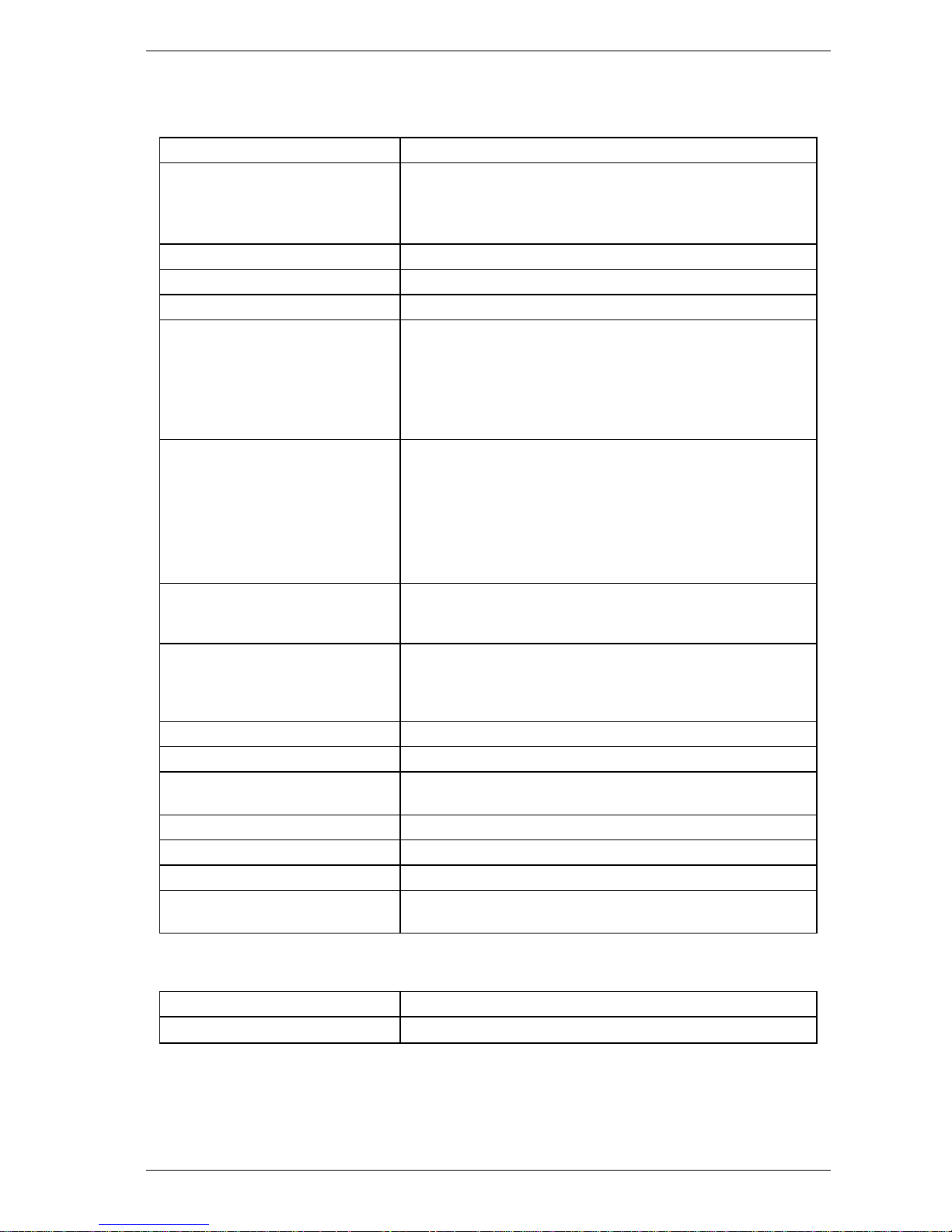
2.2.3 USB Port
Detector configuration can be performed using the Xtralis QSC software installed on a computer connected to
the detector via the USB port. The USB port is located on the outside of the detector, beneath the shroud. It is
necessary to remove the rubber grommet in order to access this port.
Figure 2-4: USBPort
VESDA by Xtralis VESDAVLQ Product Guide
www.xtralis.com 9
2.3 Specifications
Specification Value
Supply Voltage 24 VDC nominal (18 to 30 VDC), externally supplied from UL1481
/ EN54-4 listed power supply (as appropriate to meet local
codes). Ensure that the power supply is installed in accordance
with local electrical codes.
Current Consumption 170 mA (quiescent), 190 mA (alarm)
Dimensions 260 mm x 228 mm x 110 mm (10.24in x 8.98in x 4.35in)
Weight 1.2 Kg (2.65 lbs)
Operating Conditions
(To operate the VESDA VLQ detector outside
these parameters please contact your
nearest XtralisOffice.)
Temperature:
l Tested to: -10°C to 55°C (14°F to 131°F) *
l Recommended Ambient: 0°C to 39°C (32°F to 103°F)
Humidity:
l 0-95% RH, non-condensing
Sampling Pipe Network Pipe Length:
l Linear: Up to 2 x 6 m (2 x 20 ft.)
l Branched:Up to 2 x 9 m (2 x 30 ft.)
Sampling Holes:
l 2 or 4 (1 or 2 per pipe)
Refer to Section 3.4 on page 12 for further information.
Pipe Size Accepts both metric and American standard pipe sizes:
l Metric: 25 mm (1.05 in.)
l American Pipe: IPS 21 mm (¾ in.)
Relays l 3 relays. Pre-Alarm, Fire and Fault
l Contacts rated 2A @ 30 VDC
l Programmable to latch or non-latch states
l Programmable 0 - 60 sec delay for each relay
IPRating IP30
Mounting Surface or flush mounting with optional mounting brackets.
Cable Access l Two cabling inlet points from top
l Side entry through removable partition
Cable Termination Screw terminal blocks (0.2-2.5 sq mm, 30-12 AWG)
PCConnection USB (Type 2)
Sensitivity Range 0.005% - 3% obs/m (0.0015% - 0.915% obs/ft)
Threshold Setting Range l Fire Alarm: 0.15%/m - 3%/m (0.046%/ft - 0.915%/ft)
l Pre-Alarm: 0.1%/m - 1.5%/m (0.03%/ft - 0.457%/ft)
Table2-3: VLQ Detector Specifications
* Product UL listed between 0° to 39°C (32° F to 103° F)
Specification Value
Event Log Up to 1,000 events
Table2-4: Software Features
 Loading...