

VESDA VLF-500 Product Manual

VESDA VLF-500
Product Guide
November 2017
Document: 7209
Revision: A
Build: 1
Part Number: 20297


VESDA by Xtralis VESDA VLF-500 Product Guide
Intellectual Property and Copyright
This document includes registered and unregistered trademarks. All trademarks displayed are the trademarks of
their respective owners. Your use of this document does not constitute or create a licence or any other right to use
the name and/or trademark and/or label.
This document is subject to copyright owned by Xtralis AG (“Xtralis”). You agree not to copy, communicate to the
public, adapt, distribute, transfer, sell, modify or publish any contents of this document without the express prior
written consent of Xtralis.
Disclaimer
The contents of this document is provided on an “as is” basis. No representation or warranty (either express or
implied) is made as to the completeness, accuracy or reliability of the contents of this document. The manufacturer
reserves the right to change designs or specifications without obligation and without further notice. Except as
otherwise provided, all warranties, express or implied, including without limitation any implied warranties of
merchantability and fitness for a particular purpose are expressly excluded.
General Warning
This product must only be installed, configured and used strictly in accordance with the General Terms and
Conditions, User Manual and product documents available from Xtralis. All proper health and safety precautions
must be taken during the installation, commissioning and maintenance of the product. The system should not be
connected to a power source until all the components have been installed. Proper safety precautions must be taken
during tests and maintenance of the products when these are still connected to the power source. Failure to do so
or tampering with the electronics inside the products can result in an electric shock causing injury or death and may
cause equipment damage. Xtralis is not responsible and cannot be held accountable for any liability that may arise
due to improper use of the equipment and/or failure to take proper precautions. Only persons trained through an
Xtralis accredited training course can install, test and maintain the system.
Liability
You agree to install, configure and use the products strictly in accordance with the User Manual and product
documents available from Xtralis.
Xtralis is not liable to you or any other person for incidental, indirect, or consequential loss, expense or damages of
any kind including without limitation, loss of business, loss of profits or loss of data arising out of your use of the
products. Without limiting this general disclaimer the following specific warnings and disclaimers also apply:
Fitness for Purpose
You agree that you have been provided with a reasonable opportunity to appraise the products and have made
your own independent assessment of the fitness or suitability of the products for your purpose. You acknowledge
that you have not relied on any oral or written information, representation or advice given by or on behalf of Xtralis
or its representatives.
Total Liability
To the fullest extent permitted by law that any limitation or exclusion cannot apply, the total liability of Xtralis in
relation to the products is limited to:
i. in the case of services, the cost of having the services supplied again; or
ii. in the case of goods, the lowest cost of replacing the goods, acquiring equivalent goods or having the goods
repaired.
Indemnification
You agree to fully indemnify and hold Xtralis harmless for any claim, cost, demand or damage (including legal costs
on a full indemnity basis) incurred or which may be incurred arising from your use of the products.
Miscellaneous
If any provision outlined above is found to be invalid or unenforceable by a court of law, such invalidity or
unenforceability will not affect the remainder which will continue in full force and effect. All rights not expressly
granted are reserved.
www.xtralis.com i
VESDA VLF-500 Product Guide VESDA by Xtralis
Scope
This Product Guide describes the features of the VESDA VLF-500, the specifications and functions,
installation requirements, commissioning and operation procedures. A schedule for preventative maintenance
is also provided.
Document Conventions
The following typographic conventions are used in this document:
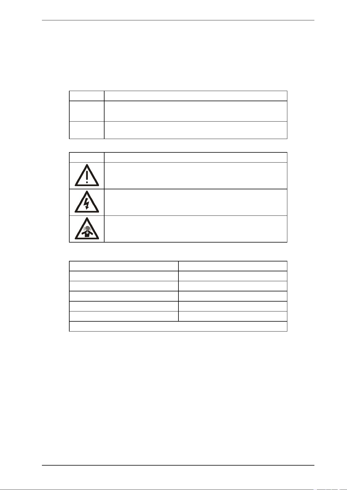
Convention Description
Bold Used to denote: emphasis.
Used for names of menus, menu options, toolbar buttons
Italics Used to denote: references to other parts of this document or other
documents. Used for the result of an action.
The following icons are used in this document:
Convention Description
Caution: This icon is used to indicate that there is a danger to
equipment. The danger could be loss of data, physical damage, or
permanent corruption of configuration details.
Contact Us
UK and Europe +44 1442 242 330
D-A-CH +49 431 23284 1
The Americas +1 781 740 2223
Middle East +962 6 588 5622
Asia +86 21 5240 0077
Australia and New Zealand +61 3 9936 7000
Warning: This icon is used to indicate that there is a danger of electric
shock. This may lead to death or permanent injury.
Warning: This icon is used to indicate that there is a danger of inhaling
dangerous substances. This may lead to death or permanent injury.
www.xtralis.com
ii www.xtralis.com

VESDA by Xtralis VESDA VLF-500 Product Guide
Codes and Standards Information for Air Sampling Smoke Detection
We strongly recommend that this document is read in conjunction with the appropriate local codes and standards
for smoke detection and electrical connections. This document contains generic product information and some
sections may not comply with all local codes and standards. In these cases, the local codes and standards must
take precedence. The information below was correct at time of printing but may now be out of date, check with your
local codes, standards and listings for the current restrictions.
FCC Compliance Statement
This equipment has been tested and found to comply with the limits for a Class B digital device, pursuant to part 15
of the FCC Rules. These limits are designed to provide reasonable protection against harmful interference in a
residential installation. This equipment generates, uses and can radiate radio frequency energy and, if not installed
and used in accordance with the instruction, may cause harmful interference to radio communications. However,
there is no guarantee that interference will not occur in a particular installation. If this equipment does cause
harmful interference to radio or television reception, the user is encouraged to try to correct the interference by one
or more of the following measures; re-orientate or relocate the receiving antenna, increase the separation between
the equipment and receiver, connect the equipment to a power outlet which is on a different power circuit to the
receiver or consult the dealer or an experienced radio/television technician for help.
FDA
This Xtralis product incorporates a laser device and is classified as a Class 1 laser product that complies with FDA
regulations 21 CFR 1040.10. The laser is housed in a sealed detector chamber and contains no serviceable parts.
The laser emits invisible light and can be hazardous if viewed with the naked eye. Under no circumstances should
the detector chamber be opened.
FM Hazardous Applications
3611 Hazardous Approval Warning: Exposure to some chemicals may degrade the sealing of relays used on the
detector. Relays used on the detector are marked “TX2-5V”, “G6S-2-5V” or “EC2-5NU”.
VESDA detectors must not be connected or disconnected to a PC while the equipment is powered in an FM
Division 2 hazardous (classified) location (defined by FM 3611).
FM Approved Applications
The product must be powered from VPS-100US-120 or VPS-100US-220 only.
ONORM F3014
ONORM F3014, transport times for all tubes (including capillaries) must not exceed 60 seconds from any hole. This
means that the predesigned pipe networks that include capillaries cannot be used.
AS1603.8
The performance of this product is dependent upon the configuration of the pipe network. Any extensions or
modifications to the pipe network may cause the product to stop working correctly. You must check that ASPIRE
approves alterations before making any changes. ASPIRE is available from your VESDA ASD distributor.
AS1851.1 2005
Maintenance Standards. Wherever this document and the AS1851.1 differ, AS1851.1 should be followed in
preference to this document.
www.xtralis.com iii

VESDA VLF-500 Product Guide VESDA by Xtralis
Regional Regulatory Requirements and Notices
UL
For open area protection the fire alarm threshold (signal) that initiates an evacuation procedure via the Fire Alarm
Panel must not be set less sensitive than 0.625%/ft. The detector can send this signal via the Fire Alarm Panel
Output signal or the Pre-alarm output signal.
Through validation testing, Underwriters Laboratories Inc. has verified that VESDA ECO gas detectors, when
installed within the sample pipe network, present no significant effects on the smoke detection performance of
VESDA. The use of the ASPIRE calculation software is required to verify system design performance with all
devices included in the design.
ActivFire
The fire alarm threshold (signal) that initiates an evacuation procedure via the Fire Alarm Panel must not be set less
sensitive than 1%m.
European Installations
The product must use a power supply conforming to EN54: Part 4.
EN54-20
The product must use a power supply conforming to EN 54-4.
The product is compliant with EN 54-20 sensitivity requirements provided the following conditions are met:
l For a Class A detector, hole sensitivity must be better than 1.5% obscuration/m and transport time less than
90 seconds
l For a Class B detector, hole sensitivity must be better than 4.5% obscuration/m and transport time less than
90 seconds
l For a Class C detector, hole sensitivity must be better than 10% obscuration/m and transport time less than
90 seconds
The product is compliant with EN 54-20 flow monitoring requirements provided the following conditions are met:
l The minor low and minor high flow thresholds should be set at 80% and 120% respectively
l The flow through the detector predicted by ASPIRE should be in the range 12 to 54 lpm
These limits should be verified using ASPIRE during the design of the sampling pipe network.
Additional information:
l Class A detectors passed EN 54-20 approvals testing with 30 holes and 0.05% obscuration/m detector
sensitivity
l Class B detectors passed EN 54-20 approvals testing with 30 holes and 0.15% obscuration/m detector
sensitivity
l Class C detectors passed EN 54-20 approvals testing with 30 holes and 0.32% obscuration/m detector
sensitivity
Product Listings
l UL
l ULC
l FM
l CCC
l ActivFire
l CE
l LPCB
l VdS
l VNIIPO
l NF
l EN 54-20
Regional approvals listings and regulatory compliance vary between VESDA product models. Refer to
www.xtralis.com for the latest product approvals matrix.
Document: 7209
Revision: A
Build: 1
Part Number: 20297
iv www.xtralis.com

VESDA by Xtralis VESDA VLF-500 Product Guide
Table of Contents
1 Introduction 3
1.1 General Notification 3
2 Installation 5
2.1 Dimensions 5
2.2 Mounting 6
2.3 Installing the Detector 7
2.4 Detector Removal 10
2.5 Air inlet pipe connections 11
2.6 Exhaust air pipe connections 11
2.7 Wiring Connections 12
2.8 RS232-compatible serial port 17
2.9 Installation Checklist 18
3 Sampling Pipe Network Design 19
3.1 Single Pipe Network 20
3.2 Branched Pipe Network 21
3.3 Return air sampling (return grilles) 22
3.4 Installation Considerations 23
3.5 Air sampling in a duct 23
4 Commissioning 25
4.1 General 25
4.2 AutoLearn Smoke 25
4.3 AutoLearn Flow 26
4.4 Xtralis VSC 26
4.5 Commissioning smoke test 26
5 Detector Overview 27
5.1 Features 27
5.2 Description 27
5.3 Applications 27
6 Product Interface 29
6.1 Front View 29
6.2 Instant Recognition Display 30
6.3 Controls and Indicators 31
6.4 Smoke level & Instant Fault Finder displays 34
7 Factory Defaults 37
8 Specifications 39
8.1 Power Supply 39
8.2 Case 39
8.3 Operating Conditions 39
8.4 Sampling Network 39
8.5 Area Covered 40
8.6 Field Wiring 40
8.7 Interfaces 40
8.8 Alarm Ranges 40
8.9 Display 40
8.10 Event Log 40
8.11 AutoLearn Smoke and Flow 40
8.12 Referencing 40
8.13 Ordering Information 41
9 Maintenance 43
www.xtralis.com 1

VESDA VLF-500 Product Guide VESDA by Xtralis
9.1 Overview 43
9.2 Maintenance Schedule 44
9.3 Replace the Filter Cartridge 45
9.4 Aspirator Replacement 46
10 Commissioning Forms 47
10.1 VESDA Commissioning Form 47
10.2 VLF-500 Detector Commissioning Form 48
10.3 Display/Relay Configuration 49
10.4 Relay Configuration 49
10.5 VESDAnet Interface Card (VIC-010) (plug-in) 49
10.6 VESDAnet Multi-Function Relay Card (VIC-020/VIC-030) 49
10.7 Ancillary Devices 50
10.8 ASPIRE Data 50
10.9 Smoke Test 50
10.10 Air Sampling Test Results 50
11 Glossary 53
12 Frequently Asked Questions (FAQ) 55
Index 57
2 www.xtralis.com
VESDA by Xtralis VESDA VLF-500 Product Guide
1 Introduction
The VESDA VLF-500 early warning air sampling smoke detector incorporates world leading VESDA very
early warning laser based aspirated smoke detection technology. It provides localized fire risk management
solutions for small, critical environments. The VLF-500 monitors areas up to 500 m² (5380 sq. ft.) dependant
on local codes and standards. The VESDA VLF complements the existing VESDA detector range and has
been designed to provide simple installation and commissioning, absolute smoke detection and reliable and
consistent response to smoke events without being affected by false alarms.
1.1 General Notification
Note: Prior to carrying out any work or maintenance on the VESDA VLF take the necessary steps to
advise the monitoring authority that power may be removed and the system disabled.
Caution: Electrostatic discharge precautions need to be taken prior to removing the front cover from the
detector otherwise damage may occur to the unit.
Attention : Il convient de prendre des précautions contre les décharges électrostatiques avant d'enlever le
capot avant du détecteur, sinon l'appareil risque d'être endommagé.
www.xtralis.com 3

VESDA VLF-500 Product Guide VESDA by Xtralis
This page is intentionally left blank.
4 www.xtralis.com
VESDA by Xtralis VESDA VLF-500 Product Guide
2 Installation
The VESDA VLF detector is shipped with all the components necessary for installation with the exception of
pipe and associated materials.
Components include:
l 1 VESDA VLF detector with fitted exhaust deflector
l 1 Mounting bracket
l 1 End of Line resistor (refer to GPI – General Purpose Input (Terminals 1 & 2) on page 13)
l 2 M4 x 20 mm locking screws
l this Product Guide
Check all components for damage and refer any concerns to your VESDA distributor.
Notes:
l Removing the rear cover of the detector will void your warranty.
l Opening or removing the sealed laser detection chamber will void your warranty.
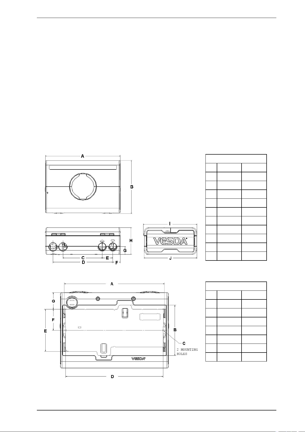
2.1 Dimensions
Legend
Figure 2-1: Dimensions of the Detector
mm inches
A 256 10.08
B 182.8 7.20
C 134.0 5.28
D 204.0 8.03
E 36.0 1.42
F 25.5 1.00
G 27.0 1.06
H 92.1 3.63
I 182.8 7.20
J 180.0 7.09
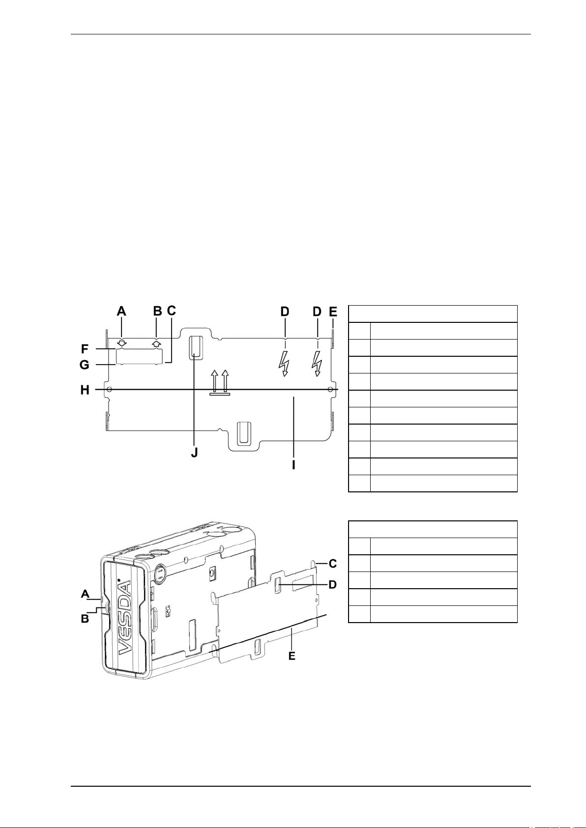
Legend
mm inches
A 236.3 9.30
B 120.0 4.72
C 4.5 0.18
D 230.0 9.06
E 100.0 3.94
F 50.0 1.97
G 40.0 1.57
Figure 2-2: Dimensions of the Detector with Mounting Bracket
www.xtralis.com 5
VESDA VLF-500 Product Guide VESDA by Xtralis
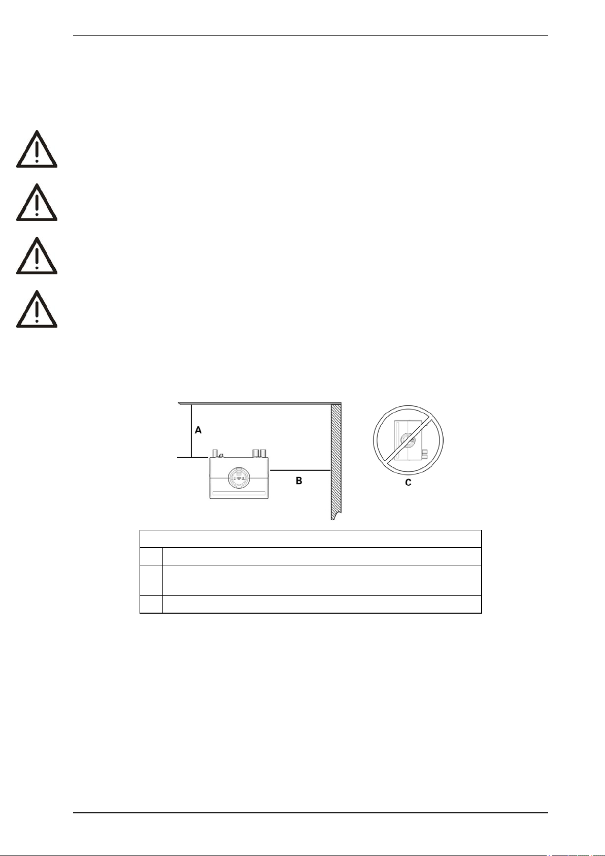
2.2 Mounting
The VESDA VLF can be installed upright, inverted or horizontally.
Note: Ensure the smoke detector is mounted away from obstructions and below ceiling level.
Caution: An exhaust deflector must be fitted for upright mounting, unless the exhaust port is connected
to a return air pipe.
Attention : Le déflecteur d'échappement est prévu pour un montage à la verticale, à moins que l'orifice
d'échappement ne soit raccordé à un tuyau de reprise d'air.
Caution: Do not install this unit on its side. There is a risk of particulate and condensation collecting on
critical elements of the detector chamber reducing the detectors performance.
Attention : N'installez pas le détecteur sur le côté. Les particules et la condensation risqueraient de
s'accumuler sur des éléments critiques de la chambre de detection, ce qui réduirait les
performances du détecteur.
Ensure that there is sufficient clearance to mount the detector, noting the location of air sampling pipes and
cable entry points. Owing to the rigid nature of the plastic pipe, installation must provide for sufficient
movement in all pipework (air inlet, air exhaust and cable pipes) to allow pipe ends to be easily fitted and
removed.
Legend
A Min. 200 mm (8 in.) below ceiling level
B Min. 500 mm (20 in.) from a wall or obstruction to allow access to the
security tab
C Do not install the detector on its side
Figure 2-3: Mounting Location
6 www.xtralis.com

VESDA by Xtralis VESDA VLF-500 Product Guide
2.3 Installing the Detector
In all installation cases the mounting bracket must be fitted (upright) as shown in Figure 2-4 on page 8.
Note: Ensure the mounting surface is flat. This will permit an air tight seal to be achieved between the
sampling pipe and the tapered air ports on the detector.
Warning: Prior to drilling the attachment holes for the mounting bracket, ensure that all mounting surfaces
(i.e. walls, cabinet sides, etc.) are clear of electrical wiring and plumbing.
Avertissement : Avant de percer les trous de fixation pour le support de montage, assurez-vous que toutes
les surfaces de montage (c'est-à-dire les murs, les côtés des armoires, etc.) ne comportent
pas de câbles électriques ni de tuyaux.
Where the pipe network and cabling are already fitted, the bracket can be used to aid alignment of the detector
with the pipes. The Installation procedure below explains this process.
www.xtralis.com 7
VESDA VLF-500 Product Guide VESDA by Xtralis
2.3.1 Installation Procedure
Cut the air inlet pipe and exhaust pipe (if used) at 90°, and to the same length (for normal and inverted
mounting). Remove all rough edges. This is critical to obtain an air tight seal with the smoke detector.
1. Position the air inlet centerline mark (A) of the mounting bracket against the end of the air inlet pipe.
Refer to Figure 2-4 below.
2. In the cut out section of the mounting bracket mark a line across the top of the cut out if metric size
pipe is used or mark a line across the bottom of the cut out if Imperial size pipe is used.
3. Slide the mounting bracket down (up for inverted mounting) until the top of the bracket aligns with the
marked line.
4. Mark off and drill the 2 bracket mounting holes (H).
5. Screw the bracket to the wall.
6. Hook the smoke detector onto the mounting bracket tabs and pull it down into place.
7. Use the two M4 x 20 mm locking screws provided and screw them into the screw holes on the left and
right side of the detector. See the items marked (F) in Figure 2-4 below.
8. The air sampling pipe can now be attached and power connected.
(Refer to Section 2.7 on page 12 for connection information).
For inverted installation, to mark off the location of the mounting holes, follow steps 1 – 4 with the mounting
bracket inverted to that shown in Figure 2-4 below. Also refer to Section 2.3.2 on page 9.
Legend
A Air inlet port centerline
B Exhaust air port centerline
C Cutout
D Cable entry centerlines
E Mounting tab
F Metric OD 25 mm pipe mark
G Imperial IPS ¾ in. pipe mark
H Bracket mounting holes
I Centerline of detector
J Anti-tamper clip
Figure 2-4: Mounting bracket orientation for upright and inverted mounting
Legend
A Security tab
B Finger clip
C Mounting tab
D Anti-tamper clip
E Centerline of detector
Figure 2-5: Mounting bracket rear view
8 www.xtralis.com
VESDA by Xtralis VESDA VLF-500 Product Guide
2.3.2 Inverting the user interface display
Caution: Electrostatic discharge precautions need to be taken prior to removing the front cover from the
detector.
Attention : Il convient de prendre des précautions contre les décharges électrostatiques avant d'enlever le
capot avant du détecteur.
For inverted mounting applications, the VESDA VLF will require the user interface display to be turned through
180°. This is carried out prior to installing the detector. Also refer to Figure 2-4 on page 8.
Inverting the user interface display:
1. Place the detector on its back, push in the securing tab and lift up the field service access door. (Refer
to Figure 6-3 on page 31).
2. Remove the 2 retaining screws and lift off the main cover.
3. Disconnect the restraining strap from the clip (C) and the ribbon cable from the user interface card (B)
and place the cover aside.
4. Open the clips (E).
5. Lift out the user interface display card, carefully turn it through 180° and then clip it back into place.
6. Reconnect the ribbon cable and the restraining strap.
7. Replace the main cover and screw down the 2 retaining screws.
8. Close the field service access door.
The detector is now ready for inverted installation.
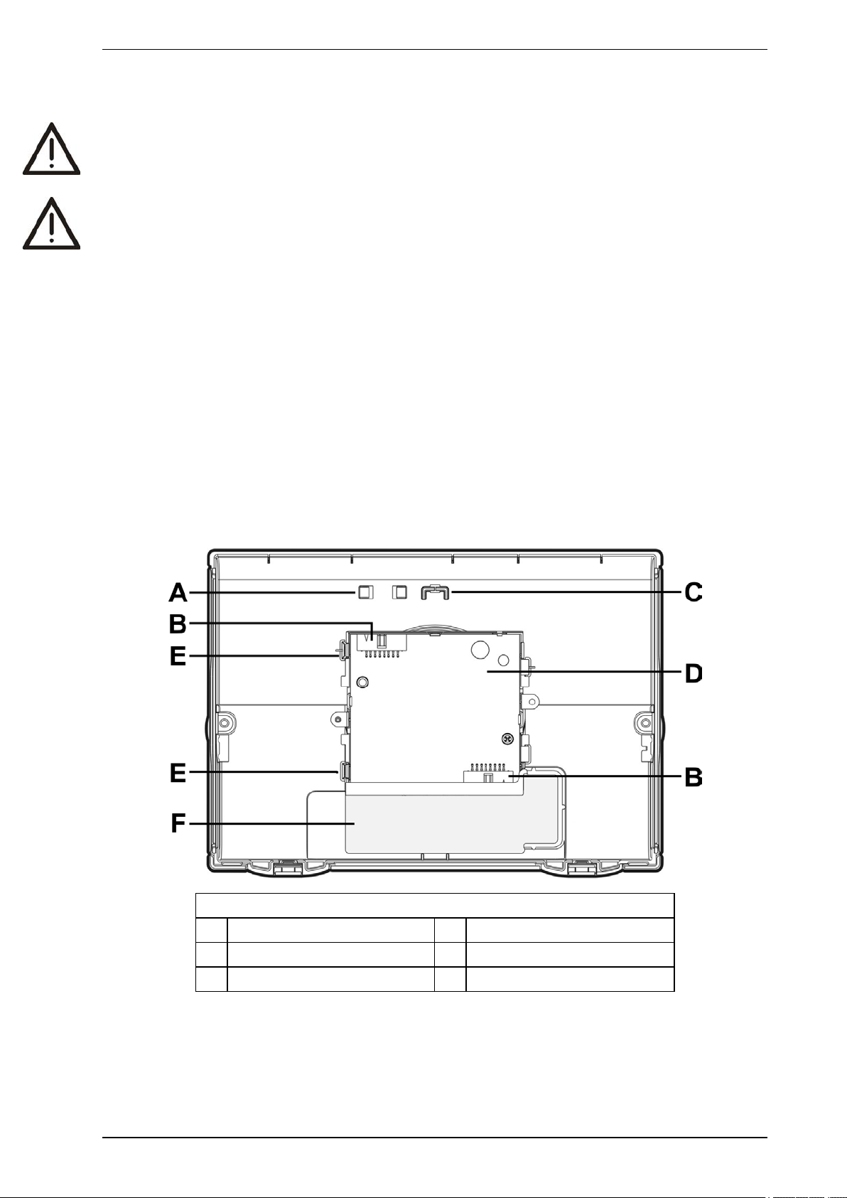
Legend
A Ribbon cable clip D Interface card
B Ribbon cable connector E Clip
C Retaining strap clip F Air filter cartridge cavity
Figure 2-6: Inside view of the front cover (as it would appear inverted)
www.xtralis.com 9
VESDA VLF-500 Product Guide VESDA by Xtralis
2.4 Detector Removal
Caution: Electrostatic discharge precautions need to be taken prior to removing the front cover from the
detector otherwise damage may occur to the unit.
Attention : Il convient de prendre des précautions contre les décharges électrostatiques avant d'enlever le
capot avant du détecteur, sinon l'appareil risque d'être endommagé.
Note: Take the necessary steps to advise the monitoring authority of work being carried out and that the
system needs to be disabled.
1. Turn off the power to the detector.
2. Disconnect the sampling pipes.
3. Push in the security tab and lift up the field service access door, refer to Figure 6-3 on page 31 for
further information.
4. Unscrew the front cover retaining screws (E).
5. Lift off and swing down the front cover, a restraining strap will take the load. For inverted mounted
detectors the cover should be removed and placed aside.
6. Disconnect all field wiring from the terminal block.
7. Unscrew the two M4 x 20 mm locking screws on the left and right side of the detector. See the items
marked (F) in Figure 2-7 below.
8. Use a screw driver to push down the anti-tamper clip in hole (A), at the same time, push the detector
base up.
9. Lift the detector off the mounting bracket.
Once the detector has been removed re-fit the front cover to keep the internal components safe from damage
and the electrical cabling safe.
Note: For inverted mounted detectors, the front cover will need to be removed prior to unhooking the
detector from the mounting bracket. Disconnect the retaining strap and the ribbon cable from the
user interface card and place the cover aside.
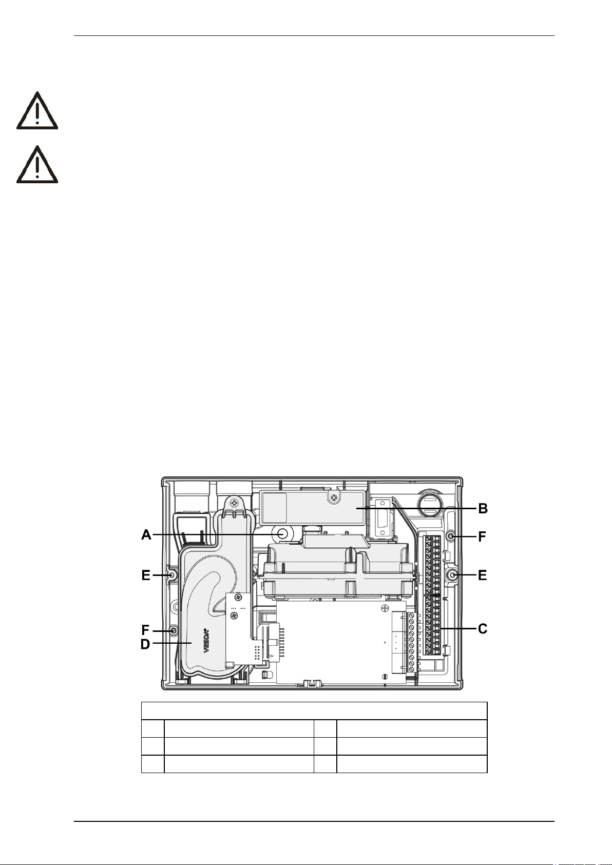
Legend
A Anti-tamper clip access hole D Aspirator
B Air Filter Cartridge E Retaining screw
C Terminal block F Bracket locking screw holes
Figure 2-7: Detector removal
10 www.xtralis.com

VESDA by Xtralis VESDA VLF-500 Product Guide
2.5 Air inlet pipe connections
The tapered shape of the air inlet port is designed to accept standard pipes of OD 25 mm (ID 21 mm) or IPS ¾
in (OD 1.05 in) and provide an air tight seal.
Note: Do not glue the air inlet pipe to the detector. This will void your warranty.
2.6 Exhaust air pipe connections
Where the VESDA VLF is located outside the protected area, consideration must be given to returning the
exhaust air to the protected environment to balance pressure differences that may exist between the two
areas. In the majority of applications, this is not necessary as pressure differences are minimal.
In some circumstances, the pre-engineered solutions in this manual may not be suitable and it is
recommended that alternate designs are verified by a suitably qualified installer using ASPIRE.
Examples of these circumstances are: where pressure differences exceed 50 Pa; in situations where the
detector is located outside the protected area; in cases where there are hazardous substances inside the
protected area eg hospital operating theatres, laboratories. In these cases, the exhaust should be returned to
the protected area.
Return air pipes need to be as short as possible to minimize the effect of airflow resistance in the return air
pipe network. Remove the fitted exhaust deflector and install a return air pipe where required.
The air exhaust port is tapered to accept standard pipes of OD 25 mm (ID 21 mm) or IPS ¾ in. and provide an
air tight seal.
Note: Do not glue the exhaust air pipe to the detector. This will void your warranty.
www.xtralis.com 11
VESDA VLF-500 Product Guide VESDA by Xtralis
2.7 Wiring Connections
Caution: Electrostatic discharge precautions need to be taken prior to removing the front cover from the
detector otherwise damage may occur to the unit.
Attention : Il convient de prendre des précautions contre les décharges électrostatiques avant d'enlever le
capot avant du détecteur, sinon l'appareil risque d'être endommagé.
2.7.1 Detector cabling requirements
The screw type terminals located on the termination card within the VESDA VLF will accept wire sizes from
0.2 mm² to 2.5 mm² (30 – 12 AWG).
Refer to Codes and Standards Information for Air Sampling Smoke Detection on page iii for code-specific
requirements.
Refer to the VESDA System Design Manual for cabling details.
To reach the terminal block, open the field service access door, refer to Section 6.3 on page 31, and then
unscrew the front cover retaining screws. Lift off and swing down the front cover. The terminal block is located
on the right hand side of the detector.
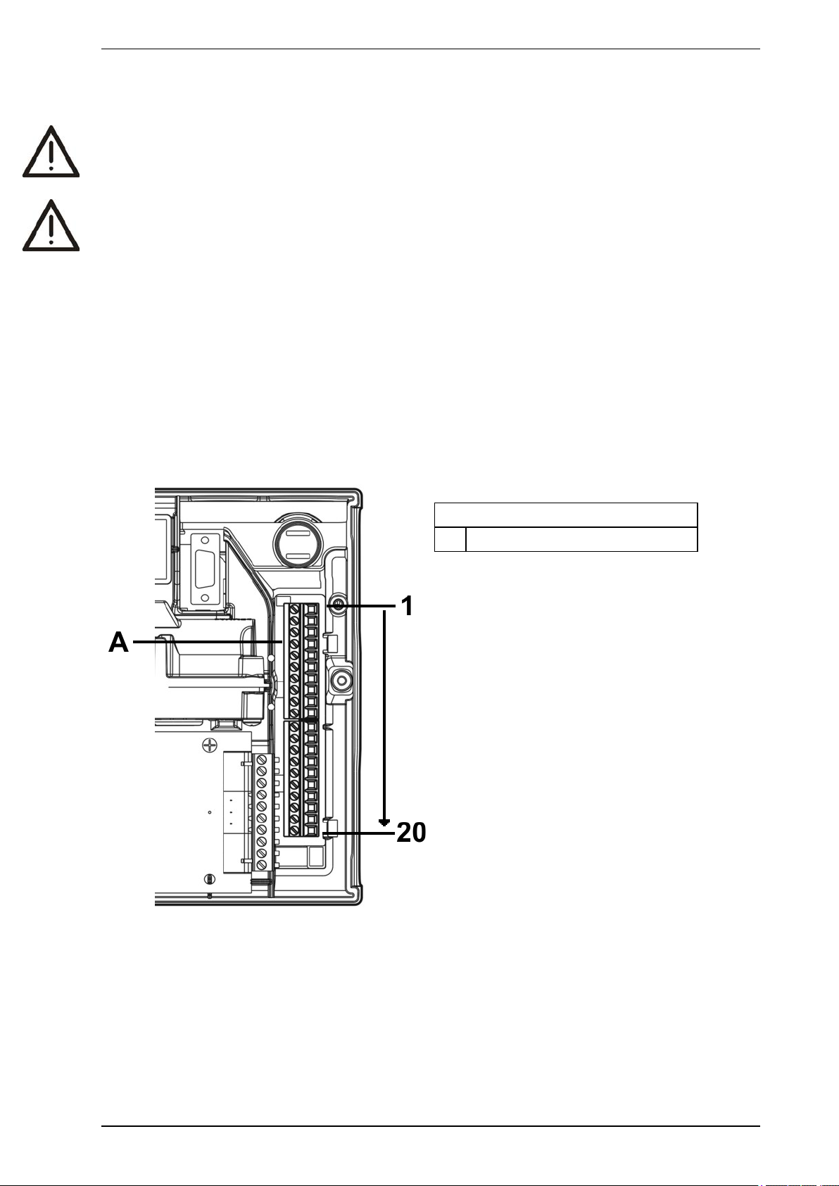
Legend
A Terminal block, connectors 1-20
Figure 2-8: Terminal Block
12 www.xtralis.com
VESDA by Xtralis VESDA VLF-500 Product Guide
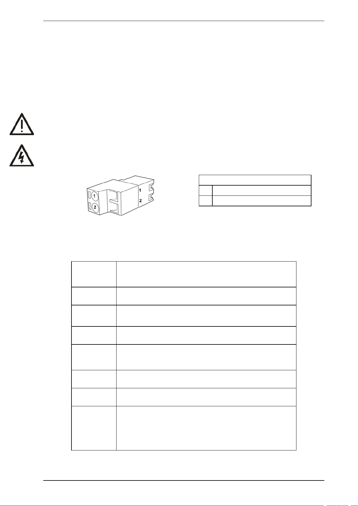
2.7.2 GPI – General Purpose Input (Terminals 1 & 2)
The General Purpose Input (GPI) is a programmable input. When the GPI function parameter is set to
external, the detector shall indicate an external equipment fault condition by monitoring the line impedance. An
End of Line (EOL) resistor is supplied with the product and must be assembled in parallel with the device to be
monitored.
The EOL resistor provides a known termination to the external equipment, this allows the VESDA VLF to
detect open or short circuits. The detector monitors the EOL resistor (Figure 2-10) and reports any faults when
the GPI function is set to any value, except None.
Caution: These terminal blocks come assembled and should NOT be disassembled.
Avertissement : Ces borniers sont livrés montés et ne doivent PAS être démontés.
Legend
A GPI Pin 1
B GPI Pin 2
Figure 2-9: Terminal and plug set up, GPI connections
The GPI function parameter can be set to the values shown in the table below to achieve several different
functions:
Table 2-1: GPI programming
GPI Function
parameter
value
None GPI is disabled. If GPI will not be used we recommend that you
Reset Detector is reset on activation of the GPI (closing contact).
Disable Detector is disabled while GPI is active (contact closed) and reset on
Standby Detector is placed in standby (disabled, plus aspirator turned off)
Result
leave the EOL resistor assembled.
Note: The factory-default value of the GPI function is Reset.
de-activation of the input (contact open).
while GPI is active (contact closed) and reset on de-activation of the
input (contact open).
Alarm set 1 Activation of GPI forces alarm threshold set 1 to be used. It overrides
normal selection.
Alarm set 2 Activation of GPI forces alarm threshold set 2 to be used. It overrides
normal selection.
External Detector indicates a fault while the GPI is active (contact closed).
Typically this is used to monitor external power supply units.
Note: If the contact is closed it will raise an Instant Fault Finder
No.6 fault. If wire is broken to the monitoring device it will
raise an Instant Fault Finder No.8 fault.
The GP input detects a short circuit (e.g. the PSU fault relay) at or below 100 Ohms.
www.xtralis.com 13
VESDA VLF-500 Product Guide VESDA by Xtralis
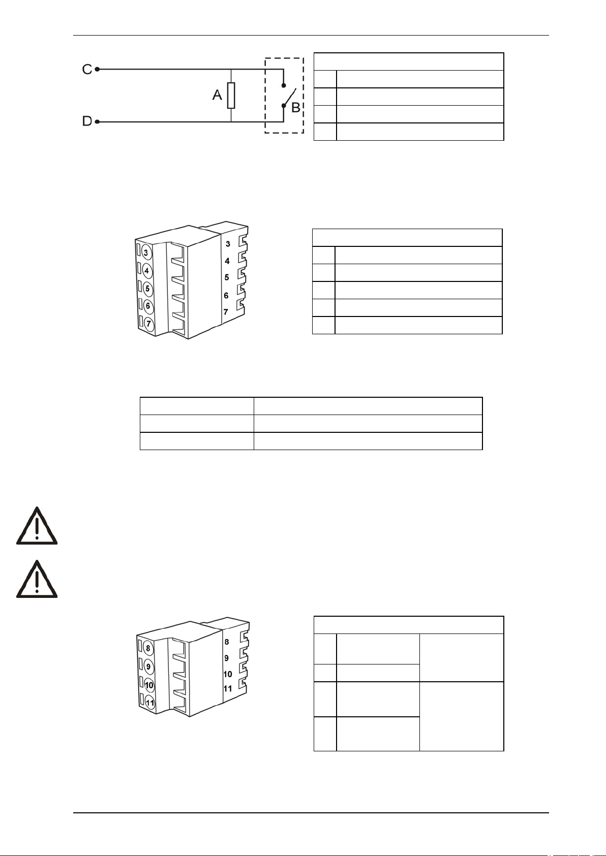
Legend
A End of Line Resistor (2.7k)
B External device (1 to N)
C GPI Pin 1
D GPI Pin 2
Figure 2-10: Triggering of GPI
2.7.3 Extra terminals (Terminals 3, 4, 5, 6 & 7)
Terminals reserved for future use.
Legend
3 Display Tx
4 Display Rx
5 Display Comm Gnd
6 Display Power -
7 Display Power +
Table 2-2: Terminal block display, spare power terminals
2.7.4 Power supply (Terminals 8, 9, 10 & 11)
Operating voltage: 24 VDC nominal (18 - 30 VDC)
Power consumption: 9.8 W nominal, 11.7 W in alarm
Current consumption: 410 mA nominal, 490 mA in alarm
It is recommended that the power supply be compliant with local codes and standards required by the regional
authority. For code-specific information, refer to Codes and Standards Information for Air Sampling Smoke
Detection on page iii.
Caution: Check the product termination wiring label during installation and subsequent maintenance
visits.
Attention : Vérifiez l'étiquette de câblage de terminaison à la pose et lors des visites de maintenance
ultérieures.
Legend
8 Power Return
0VDC
9 Power in 24VDC
10 Power Return
0VDC
11 Power Out
24VDC
Figure 2-11: Terminal block display, power supply
14 www.xtralis.com
From power
supply unit
To next detector
(if more than 1
detector per
Power Supply
Unit)
 Loading...