

VESDA lasercompact VLC-500, lasercompact VLC-505 Product Manual

SDA
®
VVEESSD
DAA LaserCOMPACT
™
PRODUCT MANUAL
VLC-500 (Relays Only) Model
VLC-505 (VESDAnet) Model
March 2000
Version 1.0

Publication history
Release 1.0 February 2000
Copyright Information
©2000 Vision Systems – VESDA™. All Rights Reserved. VESDA is a registered trademark of Vision
Products Pty Ltd. VESDA LaserPLUS, LaserSCANNER, LaserCOMPACT, AutoLearn, InfoWORKS,
ASPIRE, VSM, VESDAnet and VESDAlink are trademarks of Vision Products Pty Ltd.
Disclaimer
In accordance with its policy of continuing product and system improvement, Vision Products reserves the
right to change designs or specifications without obligation and without further notice.
Codes and Standards Information
Vision Products strongly recommends that this guide is read in conjunction with the appropriate local codes
and standards for smoke detection systems and electrical connections. This guide contains generic
information and some Sections may not comply fully with all local codes and standards. In these cases, the
local codes and standards must take precedence.
FCC Compliance Statement
This equipment has been tested and found to comply with the limits for a Class B digital device, pursuant to
part 15 of the FCC Rules. These limits are designed to provide reasonable protection against harmful
interference in a residential installation. This equipment generates, uses and can radiate radio frequency
energy and, if not installed and used in accordance with the instruction, may cause harmful interference to
radio communications. However, there is no guarantee that interference will not occur in a particular
installation. If this equipment does cause harmful interference to radio or television reception, the user is
encouraged to try and correct the interference by one or more of the following measures:
• Reorientate or relocate the receiving antenna
• Increase the separation between the equipment and receiver
• Connect the equipment to a power outlet which is on a different power circuit from which the receiver is
connected
• Consult the dealer or an experienced radio/television technician for help
FM 3611 Hazardous Approval Warning
Exposure of some chemicals may degrade the sealing of relays used on the detector. Relays used on the
detector are marked "TX2-5V" or "G6S-2-5V" or "EC2-5NU".
UL Warning
The fire alarm threshold (signal) that initiates an evacuation procedure via the Fire Alarm Panel must not be
set higher than 0.625%/ft. The COMPACT unit can send this signal either via the Fire Alarm Panel Output
signal or the Pre-alarm output signal.
Approvals and Standards
The product complies with the following standards.
AS 1603.8 FCC Class B
AS/NZS 3548 AS2211
EN50081-1 21 CFR 1010.2
EN50130-4 21 CFR 1010.3
EN 60950
Safety Label
The LaserCOMPACT incorporates a Laser device and is classified as a Class 1 Laser product which
complies with FDA Regulations 21 CFR 1040.10 and 1040.11. The laser is housed in a sealed Detector
chamber and contains no serviceable parts. This laser emits invisible light and can be hazardous if viewed
with the naked eye. Under no circumstances should this chamber be opened.
There is a safety label on
the chamber as shown below.
Figure 1 The Laser Warning Label

Contents
1. Overview.........................................................................................................................2
2. Product Description.......................................................................................................3
2.1 Front View of LaserCOMPACT........................................................................................3
2.2 Product Model, Approvals and Standards Label..............................................................3
2.3 Operation .........................................................................................................................4
2.3.1 LED and Reset/Isolate Push Button Switch Functions ............................................4
2.4 Factory Default Settings...................................................................................................5
2.4.1 Factory Default User Levels.....................................................................................5
2.4.2 Factory Default PIN Numbers..................................................................................5
2.5 LaserCOMPACT Detector Models...................................................................................5
2.5.1 Relays Only (RO) Model (Part No. VLC 500)........................................................... 5
2.5.2 VESDAnet (VN) Model (Part No. VLC 505) ............................................................5
2.6 Detector Mounting............................................................................................................6
2.7 Relay Outputs ..................................................................................................................6
2.8 Auxiliary Terminals...........................................................................................................7
2.9 Cable Entry Ports.............................................................................................................7
2.10 Event Log.........................................................................................................................7
3. Assembly Description ...................................................................................................8
3.1 Assembly Description.......................................................................................................8
3.2 Front Cover and LEDs ................................................................................................... 10
3.3 Termination Card ...........................................................................................................10
3.4 Cable Entry Ports...........................................................................................................10
3.5 Air Inlet Port ...................................................................................................................10
3.6 Air Filter Cartridge..........................................................................................................10
3.7 Aspirator.........................................................................................................................11
3.8 Air Exhaust Port.............................................................................................................11
3.9 Laser Detection Chamber..............................................................................................11
3.10 Processor Card..............................................................................................................11
4. Termination Card Details ............................................................................................12
4.1 Wire Terminal Location for RO Model ...........................................................................12
4.2 Wire Terminal Location for VN Model............................................................................ 12
4.3 Power Terminals............................................................................................................13
4.4 VESDAnet Terminals (VN Model only) ..........................................................................13
4.5 Relay Terminals.............................................................................................................14
4.6 Programming Socket .....................................................................................................15
4.7 Auxiliary Terminals.........................................................................................................15
4.7.1 Bias Terminals .......................................................................................................15
4.7.2 Reset Terminals (General Purpose Input) .............................................................16
4.7.3 Remote LED Terminals..........................................................................................16
5. Specifications...............................................................................................................17
6. Factory Default Settings..............................................................................................18
7. Alarm Threshold Settings ...........................................................................................19
8. Physical Dimensions...................................................................................................20
9. Parts Replacement....................................................................................................... 22
9.1 Opening the Detector.....................................................................................................23
9.2 Closing the Detector.......................................................................................................23
9.3 Replacing the Air Filter Cartridge................................................................................... 23
9.4 Replacing the Aspirator..................................................................................................24

LaserCOMPACT Product Manual VESDA
®
2 Version 1.0
1. Overview
The LaserCOMPACT is an aspirating sm oke detec tor that provides all the benefits of aspirating
smoke detection, including very early warning, for small areas. The LaserCOMPACT has been
designed to protect areas up to 500sq.m (5,000sq.ft).
The detector operates by drawing air from a pr otected area via a pipe network . A sam ple of the
air is filtered to remove dust and dirt before it is passed through the laser detec tion chamber.
Smoke present in the detection chamber creates light scattering, which via sophisticated
electronics produces a signal representing the absolute level of smoke present.
The LaserCOMPACT can be pr ogrammed to have 2 or 3 alarm thresholds, which can be set
across its wide sensitivity range to provide both very early warning of a potential fire situation
and allow the initiation of further control procedures should the smoke level increase.
All pipe network designs for the LaserCOMPACT should be supported by the ASPIRE Pipe
Modelling program results.
VESDA products are only distributed through trained and accredited channels.
It is understood that personnel installing this equipm ent are fam iliar with the VESDA technology
and have a good understanding of local codes and standards regarding electrical cabling.
Installation engineers should be certified where appropriate.
For details of your nearest Accredited Distributors please contact Vision Systems – VESDA.
Contact details are at the back of this document.
VESDA
®
LaserCOMPACT Product Manual
Version 1.0 3
2. Product Description
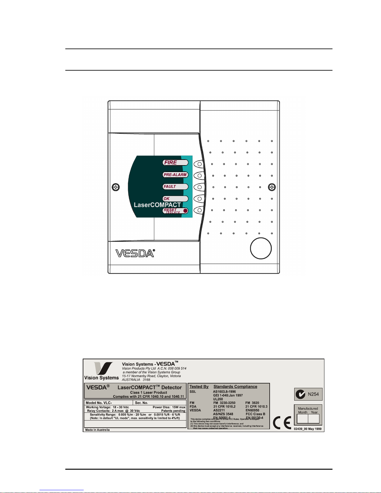
2.1 Front View of LaserCOMPACT
Figure 1 Front View of LaserCOMPACT Model
2.2 Product Model, Approvals and Standards Label
A label similar to that shown in Figure 2 is located at the bottom of the LaserCOMPACT
enclosure and displays the detector model, approvals and standards.
Figure 2 Label Details

LaserCOMPACT Product Manual VESDA
®
4 Version 1.0
2.3 Operation
2.3.1 LED and Reset/Isolate Push Button Switch Functions
Refer to Figure 5 for the location of the LED indic ators. The functions of the LED indicator s on
the front panel from top to bottom and the push button Reset/Isolate switch are:-
Fire
This RED LED lights up when the Fire alarm threshold is initiated.
Pre-Alarm
This RED LED lights up when the Pre-Alarm threshold is initiated.
This LED flashes when the Alert alarm threshold is initiated and
*Alert Overlay in ON.
*The option to have an Alert warning is set in the programming as
Alert Overlay. When this condition is ON the LED will flash and the
fault relay changes states in an Alert condition.
Fault
This YELLOW LED lights when a fault condition occurs.
It is also lit during airflow normalisation.
OK This Green LED stays lit during normal operation; showing the unit is
healthy.
This LED flashes twice repeatedly during air flow normalisation and/or
three times repeatedly during AutoLearn.
Reset/Isolate
This Yellow LED is lit when the unit is Isolated. During this condition
the Pre-Alarm and/or Fire relay is de-energised (unlatched) if the
relays have previously been energised (latched).
(The default setting for the Fault relay is the energised (latched) state
unless altered during programming).
Reset/Isolate
Push Button
Switch
To Reset the unit, press this switch once.
To Isolate the unit, press and hold the switch for 2 seconds.
To De-isolate the unit, press and hold the switch again for 2 seconds.
While the detector is Isolated, any faults m ay be cleared by pressing
this switch once.
If a remote Reset switch has been f itted to the Reset term inals and is
set to the Isolate position
OR
If the Reset/Isolate button has been locked out in the programming,
this switch will not operate. Refer to Section 2.8 and 4.7.

VESDA
®
LaserCOMPACT Product Manual
Version 1.0 5
2.4 Factory Default Settings
The LaserCOMPACT is s hipped from the factory with the default settings as per the table in
Section 6.0. Only authorised personnel at the Administrative (ADM) or Distributor (DST) level
may alter these values.
2.4.1 Factory Default User Access Levels
The factory set default access levels are 1 User ( USR), 1 Adm inistrator (ADM) and 1 Dis tributor
(DST). Each level requires a four-digit PIN num ber to be entered before gaining access to the
detector. The user m ay add, alter, delete or modify user names and PINs after having gained
access into the system. Up to 10 Users and 4 Administrators may be added.
2.4.2 Factory Default PIN Numbers
The factory default Personal Identification Numbers (PIN) are distributed to authorised personnel
attending accredited VESDA training courses and may be altered after gaining access into the
system.
2.5 LaserCOMPACT Detector Models
The LaserCOMPACT comes in two models and are as follows:-
2.5.1 Relays Only (RO) Model (Part No. VLC 500)
This model is used as a single stand-alone smoke detector and is not connected into
VESDAnet. The model is identified by the part number (VLC-500) which is located on a label at
the bottom of the enclosure (See Figure 2)
Programming this detector is by connecting a PC with a RS232 communication cable to the 9
pin programming socket on the termination c ard located inside the detector. Run the VConfig
Pro or VConfig Basic program from the PC to program.
2.5.2 VESDAnet (VN) Model (Part No. VLC 505)
This model is used when the detector is to be connec ted into VESDAnet. The model is identif ied
by the part number (VLC-505) which is located on a label at the bottom of the enc losure (See
Figure 2)
Communication to this detector is performed by one of the following methods:-
• Connect a LCD Programmer to the 15 pin programming socket on the termination card
OR
• Connect a PC to the 15 pin programming sock et via a PC-Link HLI device and running the
VConfig Pro of VConfig Basic program from the PC
OR
• To a VESDAnet socket from a remote Programmer or PC.
This detector can be used as a stand-alone device and not connected into VESDAnet. In this
configuration, the VESDAnet terminals must be linked. Refer to Section 4.4.
LaserCOMPACT Product Manual VESDA
®
6 Version 1.0
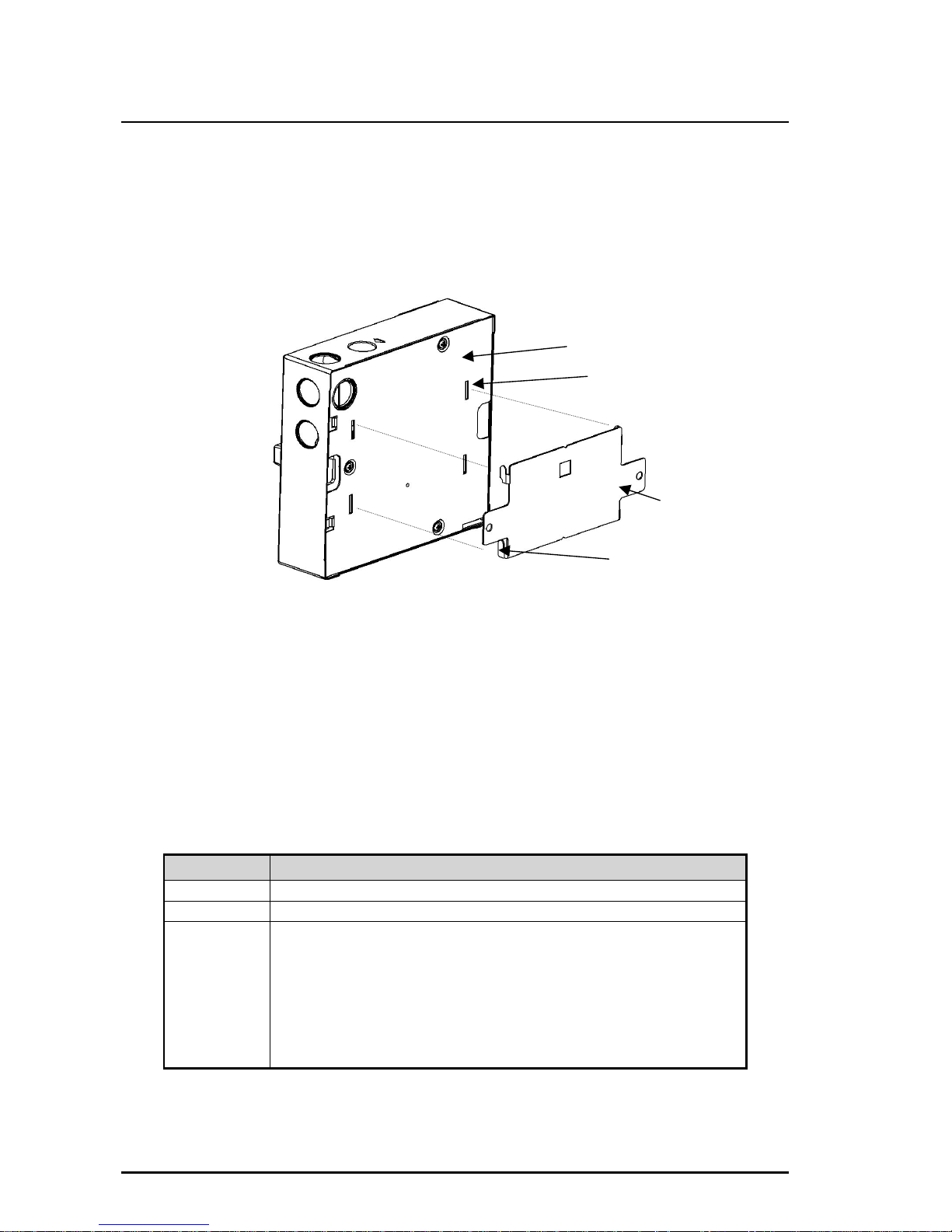
2.6 Detector Mounting
The LaserCOMPACT com es with a separate metal mounting brack et that is attached onto the
mounting location. The detector can only be mounted with the supplied mounting brack et. The
back of the detector is s lotted over the four tabs on the m ounting br acket and is locked in place
with an anti-tamper screw located inside the enclosure. Refer to Figure 3 for mounting and
Figure 6 for the anti tamper screw location.
Figure 3 Mounting the Detector onto the Mounting Bracket
2.7 Relay Outputs
There are three relays (Fire, Pre-Alarm and Fault) for interfacing to ex ternal devices or to the
Fire Alarm Panel. The relays are programmable to the energised (latched) or de-energised (nonlatched) states via a PC or LCD Program mer. Refer to the table below for the c onditions for
these relays to change states.
Note: The Fault relay is set to the energised (latched) state on power up and is de-energised
(unlatched) when a fault or Alert condition is present. Connec tion is made between the
NO and C terminals when the relay is energised.
RELAY CONDITIONS FOR RELAYS TO CHANGE STATES
Fire Fire alarm smoke threshold level is initiated. (Relay is energised)
Pre-Alarm Pre-Alarm smoke threshold level is initiated. (Relay is energised)
Fault Fault found on detector or on VESDAnet loop.
Air flow Normalisation is initiated.
System Isolation is initiated.
(Relay is de-energised for all three conditions above)
When the Overlay Alert function has been selected and when the
Alert smoke threshold level has been initiated or when a fault is
present. (Relay is de-energised)
Note: The above relay states are not applicable when the relay states are reprogrammed by the
user.
Back of the box
Mounting bracket
Bracket tab X 4
Rectangular Slots X 4

VESDA
®
LaserCOMPACT Product Manual
Version 1.0 7
2.8 Auxiliary Terminals
The auxiliary terminals on the term ination card are Bias, Reset and LED. Refer to Section 4.7
for wire connection details. These terminals have the following functions:-
Bias terminals These output terminals provide 10VDC supply to power the Reset input
terminals via a remote ON/OFF switch.
LED terminals These output terminals pr ovide a 5V, 15mA DC supply via a 220 ohm resistor
to drive an LED located in another part of the building.
Reset terminals These terminals are also known as the General Purpose Input (GPI) and is
(GPI Input) used for one of these three functions; Reset, Mains OK or Standby. The
Reset terminals can be programmed to one of the functions if required and
requires 5V to 33VDC to operate. Any input into this terminal overrides the
Reset switch on the front panel. These functions operate as follows:-
Reset/
Isolate
The detector Isolates when ≥ 5 VDC is applied to this terminal and
Reset when the voltage drops ≤ 2 VDC.
Mains
OK
The detector monitors the state of the external power supply and
responds to the following conditions.
Mains OK ≥ 5 VDC is at this terminal
Mains Fail ≤ 2 VDC is at this terminal
Standby
The detector Isolates and the aspirator turns OFF when ≥ 5 VDC is at
this terminal.
Note: The input states are not defined for any voltages > 2 to < 5 VDC.
2.9 Cable Entry Ports
There are four 25 m m (1in) ∅ cable entry ports on the top right hand side of the detector. Any of
the ports can be used to run the cables into the detector. Refer to Figure 4, 6 and Section 3.4 for
more details.
2.10 Event Log
The detector stores and logs up to a maximum of 12,000 events on a first in fir st out basis. By
regulation, detectors are normally required to be powered from a battery backed DC power
supply. This ensures that the log is held indefinitely. If it is required to totally remove the DC
power source and it is considered the log may hold useful then the user should download the log
into a PC using VConfig Pro software program before disconnecting the DC power.
 Loading...