

Page 1
LaserCOMPACT
Product Guide
August 8, 2007
Document Number: 10280_04
Part Number: 18938
FlameStop is a Distributor for VESDA ASD Products
www.flamestop.co.nz
Page 2

LaserCOMPACT Product Guide VESDA
®
2
Page 3
VESDA
®
LaserCOMPACT Product Guide
i
Intellectual Property and Copyright
This document includes registered and unregistered trademarks. All trademarks displayed are the trademarks of their respective owners.
Yo ur use of this document does not constitute or create a licence or any other right to use the name and/or trademark and/or label.
This document is subject to copyright owned by Xtralis AG (“Xtralis”). You agree not to copy, communicate to the public, adapt, distribute,
transfer, sell, modify or publish any contents of this document without the express prior written consent of Xtralis.
Disclaimer
The contents of this document is provided on an “as is” basis. No representation or warranty (either expre ss or implie d) is mad e as to the
completeness, accuracy or reliability of the contents of this document. The manufacturer reserves the right t o change designs or
specifications without obligation and without further notice. Except as otherwise provided, all warranties, express or implied, including
without limitation any implied warranties of merchantability and fitness for a particular purpose are expressly excluded.
General Warning
This product must only be installed, configured and used strictly in accordance with the General Terms and Conditions, User Manual and
product documents available from Xtralis. All proper health and safet y precautions must be taken during the installation, commissioning
and maintenance of the product. The system should not be connected to a power source until all the components have been installed.
Proper safety precautions must be taken during tests a nd maintenance of the product s when th ese are still connect ed to the powe r source.
Failure to do so or tampering with the electronics inside the product s can result in an electric shock causing injury or death and may cause
equipment damage. Xtralis is not responsible and cannot be held accountable for any l i ability that may arise due to improper use of the
equipment and/or failure to take proper precautions. Only persons t rained through an Xtralis accredited tra ining course can ins tall , test and
maintain the system.
Liability
Yo u agree to install, configure and use the products strictly in accordance with the User Manual and product documents available from
Xtralis.
Xtralis is not liable to you or any other person for incidental, indirect, or consequential loss, expense or damages of any kind including
without limitation, loss of business, loss of profits or loss of dat a arising out of your use of the products. Without limiting this general
disclaimer the following specific warnings and disclaimers also apply:
Fitness for Purpose
You agree that you have been provided with a reasonable opportunity to appraise the product s and have made your own independent
assessment of the fitness or suitability of the products for your purpose. You acknowledge that you have not relied on any oral or writte n
information, representation or advice given by or on behalf of Xtralis or its representatives.
Total Liability
To the fullest extent permitted by law that any limitation or exclusion cannot apply, the total liability of Xtrali s in relation to the products is
limited to:
(i) in the case of services, the cost of having the services supplied again; or
(ii) in the case of goods, the lowest cost of replacing the goods, acquiring equivalent goods or having the goods repaired.
Indemnification
You agree to fully indemnify and hold Xtralis harmless for any claim, cost, demand or damage (including leg al costs on a full indemnity
basis) incurred or which may be incurred arising from your use of the products.
Miscellaneous
If any provision outlined above is found to be invalid or un enforceab le by a court o f law, such invalidity or unenforceability will not affe ct the
remainder which will continue in full force and effect. All rights not exp ressly granted are reserved.
Document Conventions
The following typographic conventions are used in this document.
The following icons are used in this document
Convention Description
Bold Used to denote: emphasis
Used for names of menus, menu options, toolbar buttons
Italics Used to denote: references to other parts of this document or
other documents. Used for the result of an action.
Convention Description
Caution: This icon is used to indicate that there is a danger to
equipment. The danger could be loss of data, physical damage,
or permanent corruption of configuration details.
Warning: This icon is used to indicate that there is a danger of
electric shock. This may lead to death or permanent injury.
Page 4
LaserCOMPACT Product Guide VESDA
®
ii
Contact Us
Codes and Standards Information for Air Sampling Smoke Detection
We strongly recommend that this document is read in conjuncti on wi th t he appr opria te local code s and standards for smoke detection and
electrical connections. This document contains generic product inf ormation and some sections may not comply with all local codes and
standards. In these cases, the local codes and standards must take precedence. The information below was correct at time of printing but
may now be out of date, check with your local codes, standards and listings for the current restrictions.
FCC Compliance Statement
This equipment has been tested and found to comply with the limits for a Class B digital device, pursuant to part 15 of the FCC Rules.
These limits are designed to provide reasonable protection against harmful interference in a residential installation. This equipment
generates, uses and can radiate radio frequency energy and, if not installed and used in accordance with the instruction, may cause
harmful interference to radio communications. However, there is no guarantee that interference will not occur in a particular installation. If
this equipment does cause harmful interference to radio or television recep tion, t he u ser i s encou raged to t ry to corre ct the in t erfer ence b y
one or more of the following measures; re-orient ate or relo cate t he receiving antenna, incre ase the sep ara tion betwe en the equip ment and
receiver, connect the equipment to a power outlet which is on a different power circuit to the receiver or consult the dealer or an
experienced radio/television technician for help.
FDA
This VESDA product incorporates a laser device and is classified as a Class 1 laser product that complies with FDA regulations 21 CFR
1040.10. The laser is housed in a sealed detector chamber and contains no serviceable parts. The laser emits invisible light and can be
hazardous if viewed with the naked eye. Under no circumstances should the detector chamber be opened.
FM
3611 Hazardous Approval Warning: Exposure to some chemicals may degrade the sealing of re lays used on t he detecto r. Relays used on
the detector are marked “TX2-5V”, “G6S-2-5V” or “EC2-5NU”.
VESDA detectors must not be connected or disconnected to a PC while the equipment is powered in an FM Division 2 hazardous
(classified) location (defined by FM 3611).
FM Approved Applications
The product must be powered from VPS-100US-120, VPS-100US-220 or VPS-220 only.
ONORM F3014
ONORM F3014, transport times for all tubes (including capillaries) must not exceed 60 seconds from any hole. This means that the predesigned pipe networks that include capillaries cannot be used.
AS1603.8
The performance of this product is dependent upon the configuration of the pipe network. Any extensions or modifications to the pipe
network may cause the product to stop working corre ctly. You must check that ASPIRE2 appro ves alterat ions before making any changes.
ASPIRE2 is available from your VESDA ASD distributor.
AS1851.1 2005
Maintenance Standards. Wherever this document and the AS1851.1 differ, AS1851.1 should be followed in preference to this document.
European Installations
The product must use a power supply conforming to EN54: Part 4.
Approvals and Standards
The product complies with the following standards.
AS1603.8-1996
GEI 1-048:Jan 1997
UL268 UL 268A
FM 3230-3250 FM3820
21 CFR 1010.2 21 CFR 1010.3
AS2211
AS/NZS 3548
Warning: This icon is used to indicate that there is a dang er of
inhaling dangerous substances. This may lead to death or
permanent injury.
The Americas +1 781 740 2223
Asia +852 2297 2438
Australia and New Zealand +61 3 9936 7000
Continental Europe +41 55 285 99 99
UK and the Middle East +44 1442 242 330
www.xtralis.com
Page 5

VESDA
®
LaserCOMPACT Product Guide
iii
FCC Class B
EN 61000-6-3 EN 50130-4
Document: 10280_04
Page 6

LaserCOMPACT Product Guide VESDA
®
iv
Page 7

VESDA
®
LaserCOMPACT Product Guide
v
Contents
Scope ............................................................................................................................................... 1
Introduction to LaserCOMPACT ....... .... ... ... ... ... ............................................................................. 1
LaserCOMPACT configurations ............................................................................................. 1
Features of the LaserCOMPACT ........................................................................................... 2
Operation of the LaserCOMPACT ................................................................................................. 2
LaserCOMPACT display ........................................................................................................ 3
LED and Reset/Isolate button ............................................................................................. 4
Compact (VN) Remote Display Module ..................... ................ ............. ............. ............. .. 5
LaserCOMPACT Remote Display Module ............................................................................. 6
LCD Programmer ................................... ... .... ... ... ... .... ... ... ... ............................................. ...... 8
Product Configuration ................................ .... ... ... ... .... ... ... ... ............................................. ...... 9
Product Information ..................................................................................................................... 10
Product Specification ........................ ... ... ... .... ... ... ............................................. .................... 10
Product Dimensions .................................. .... ... ... ... .... ... ... ... ............................................. ....12
Default Settings .................................................................................................................... 14
Relay settings and conditions to change states ................................................................... 15
Auxiliary / GPI Terminals ......................................................................................................15
Mounting the Detector .................................................................................................................. 16
Securing the mounting bracket ............................................................................................. 17
Installing the Detector ...................................... ... .... ... ... ... .......................................... ... .... 17
Recess mounting kit ......................................................................................................... 18
These kits are used to house a detector inside a wall cavity. ........................................... 18
Connecting the VCL to the Pipe Network ................................................................................... 18
Inlet Pipes ............................................................................................................................. 18
Air Exhaust Pipe ................................................................................................................... 19
Wiring Connections ...................................................................................................................... 19
Termination Card .................................................................................................................. 19
VESDAnet Terminals (VN Model only): ............................................................................ 21
Relay terminals ................................................................................................................. 21
Programming socket ......................................................................................................... 22
Auxiliary / GPI Terminals: ....................................................... .......................................... 22
For further information see Auxiliary / GPI Terminals on page 15 .................................... 23
Typical Wiring To Fire Alarm Control Panel (FACP) ........................................................ 23
Wiring To an Address Loop Module. ................................................................................ 24
Power source ................................................................................................................................ 24
Battery Back Up ............................................................................................................................ 25
Backup battery size calculation sheet .............................................................................. 25
Starting Up .................................................................................................................................... 25
Installation Checklist ......................... ... ... ... .......................................... .... ... ... ... .... ... ... ... ....... 27
Preliminary Systems Check ......................................................................................................... 28
Maintaining and Servicing the Detector ..................................................................................... 28
Opening and Closing the detector ........................................................................................ 29
Opening the detector ........................................................................................................ 29
Closing the detector .......................................................................................................... 29
Page 8

LaserCOMPACT Product Guide VESDA
®
vi
Replacing the aspirator ........................................................................................................30
Assembly .......................................................................................................................... 30
Internal wiring for LaserCOMPACT ...................................................................................... 31
Spare Parts .................................................................................................................................... 31
Page 9
VESDA
®
LaserCOMPACT Product Guide
1
1.1 Scope
The LaserCOMPACT Product Guide is written to provide you with comprehensive knowledge of
the detector.
This guide introduces you to the LaserCOMPACT its features, technical specifications and gives
an understanding of its components and their function. You will also find instructions on installing,
cabling and powering up the detector.
This guide is for anyone involved with the design, maintenance and purchasing of a VESDA
system. It is assumed that anyone using this guide has knowledge and the appropriate
certification from the local fire and electrical authorities.
1.2 Introduction to LaserCOMPACT
The LaserCOMPACT is an aspirating smoke detector providing very early warning of fire
conditions by drawing air samples through an air sampling pipe network. The detector chamber
can detect presence of smoke at very low concentrations. The embedded and PC software
complimenting the LaserCOMPACT provides a wide range of user defined parameters and
reporting capabilities. The detector easily interfaces with fire warning and fire suppression
release systems, and can be easily integrated into a building management system.
LaserCOMPACT configurations
The LaserCOMPACT is available as:
• Relays Only (RO) model (VLC-500) - for stand alone LaserCOMPACT
• VESDAnet (VN) model (VLC-505) - for networked LaserCOMPACT
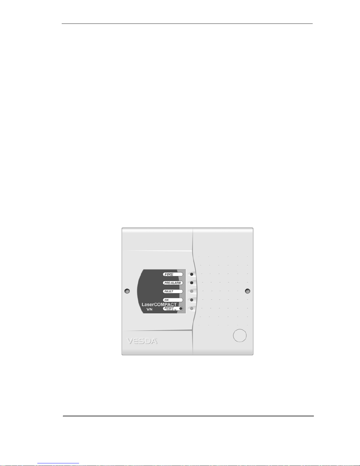
Figure 1 - VLC-505 LaserCOMPACT detector
Page 10

LaserCOMPACT Product Guide VESDA
®
2
Features of the LaserCOMPACT
The LaserCOMPACT features make it an ideal smoke detection apparatus for protecting small
environments and individual objects:
• Reduced size compared to LaserPLUS and LaserSCANNER detectors
• Wide sens
itivity range
•
Each detector can cover an area of up to 800 m
2
(8000 sq. ft.)
• Up to three programmable alarm thresholds
• Programmable relays
• AutoLearn feature
• One pipe inlet that can be split into two pipes
• Dual stage air filter cartrid
ge
•
Option for inverted mounting
• High efficiency aspirator
• Airflow monitoring
• Optional remote display and relay capability
• Active fault monitoring
• Easy cable termination
• Event log to 12000 events
• RO Version: Relay Only version for stand alone LaserCOMPACT
• VN Version: VESDAnet (VN) version for networked LaserCOMPACT
• Remote modules available (VN version only) to meet site specific requirements
• Three programmable general purpose input functions
• PC capable programming and monitoring
1.3 Operation of the LaserCOMPACT
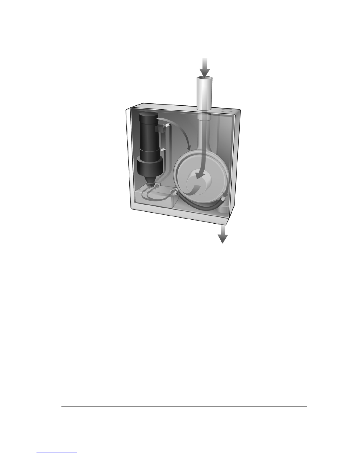
An air sampling pipe network collects air samples from a protected area. The VESDA integrated
aspirator draws air into the sampling pipes through a pipe inlet manifold. For further information
on air sampling pipe networks please see the Pipe Network Design and Installation Manuals.
Some of this air flows to the dual stage filter. The first stage air filter removes dust and dirt from
the sampled air and flows to the laser detector chamber to detect the presence of smoke.
Page 11
VESDA
®
LaserCOMPACT Product Guide
3
Any smoke detected in the laser detection chamber is signaled to the main processor card. If the
presence of detected smoke is higher than the set thresholds it is reported as a Pre-Alarm or an
Alarm depending upon the alarm thresholds. The second stage filter further filters the air to
produce ultra clean air. The ultra clean air is used to clean the optical surfaces in the laser
detection chamber.
Figure 2 - Operation and internal air flow of LaserCOMPACT Detector
LaserCOMPACT display
The LaserCOMPACT has five LEDs to indicate Alarms, Faults, OK (normal working of the
detector) and Reset/Isolate status. The LaserCOMPACT VN offers the option for a remotely
mounted Display Module, see VRT-J00 Display Module mounted into a remote unit on page 5 for
details.
Page 12

LaserCOMPACT Product Guide VESDA
®
4
LED and Reset/Isolate button
The LED indicators and the Reset/Isolate button on the front cover of the LaserCOMPACT
detector display alarms and faults.
Table 1 - LED Indicators and the Reset/Isolate button
Fire This (RED) LED is lit when the Fire alarm threshold is reached.
Pre-Alarm
The (RED) Pre-Alarm LED is lit when the Pre-Alarm threshold is reached.
This LED flashes when the Alert alarm threshold is reached and Alert
Overlay in set to ON.
Fault
This (YELLOW) LED is lit when a fault is detected.
It is also lit during airflow normalization.
OK
The OK LED (Green) stays lit during normal operation indicating the unit is
functionally normally.
This LED flashes twice repeatedly during air flow normalization operation
and three times repeatedly when AutoLearn is activated.
Reset/Isolate
The Reset/Isolate LED (Yellow) is lit when LaserCOMPACT is isolated.
While it remains isolated the Pre-Alarm and Fire relays will not work.
(The Fault relay will continue to work).
Reset /
Isolate Push
Button Switch
• To Reset the unit, press this button once.
• To Isolate the unit, press and hold the button for 2 seconds.
• To De-isolate the unit, press and hold the button for 2 seconds.
• While the detector is Isolated, any faults may be cleared by pressing this
button once.
The button will not operate:
• if a remote Reset switch has been fitted to the Reset (GPI) ter minals and
is set to the Isolate position
OR
• if the Reset/Isolate button has been locked out in the programming.
Page 13
VESDA
®
LaserCOMPACT Product Guide
5
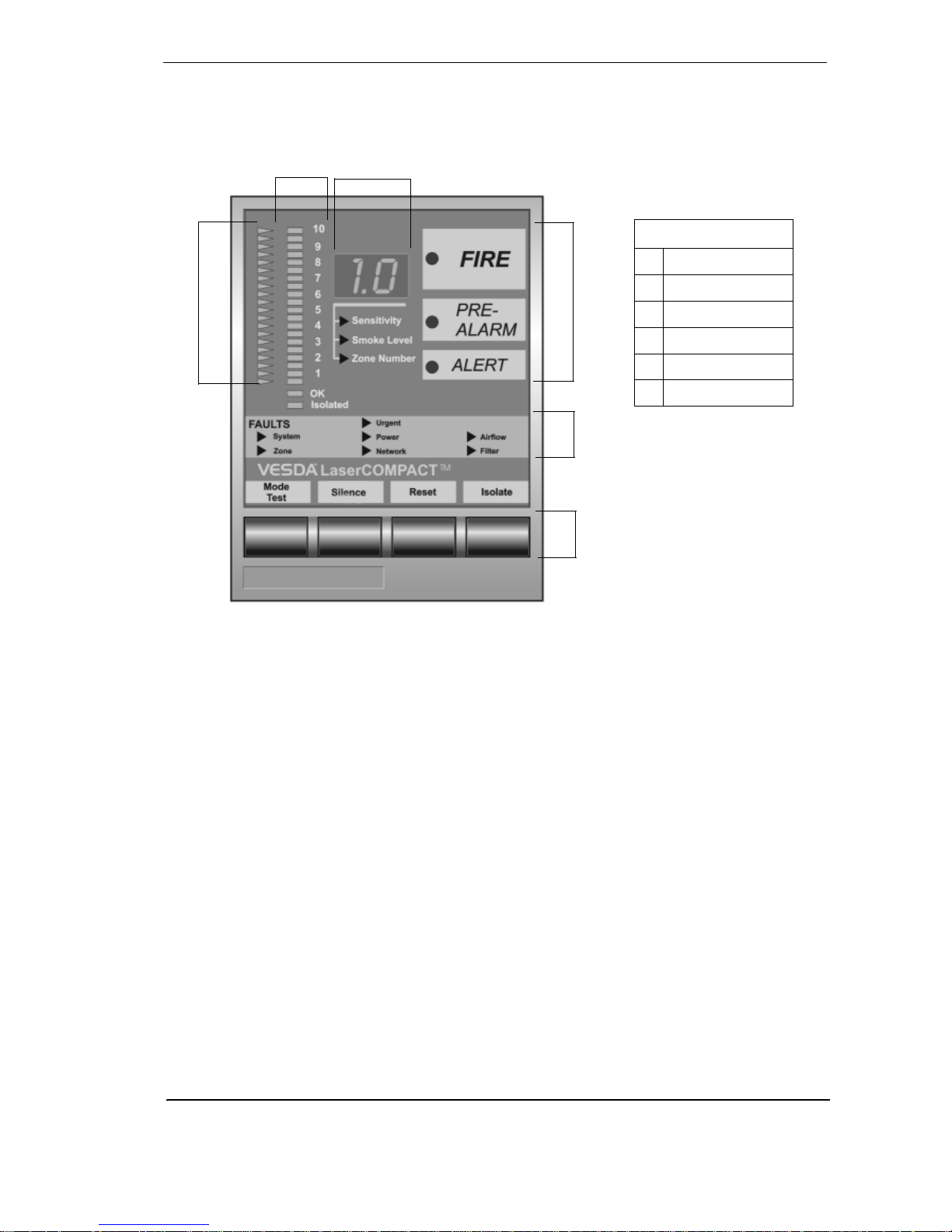
Compact (VN) Remote Display Module
The LaserCOMP ACT (VN) model has the option of being co nnected to a Remote Display Module
mounted into a Mounting Unit or a 19” Subrack. Un like the Laser PLUS a nd th e L aser SCANNER
detectors, the display module cannot be mounted into the LaserCOMPACT.
Figure 3 - VRT-J00 Display Module mounted into a remote unit
B
A
C
D
E
F
Legend
A Threshold Indicators
B Bar graph
C Numerical Display
D Alarm Level LEDs
E Fault LEDs
F Push Button Keys
Page 14
LaserCOMPACT Product Guide VESDA
®
6
LaserCOMPACT Remote Display Module
OK LED
The OK LED stays lit during normal operation indicating the unit is functioning
normally. When this LED is off a warning beep will sound indicating a Fault
condition is active.
Isolate LED
This LED is lit when the detector is Isolated a nd relay are de-activated
disabling alarm outputs of the detector. A warning sounder will beep every 60
seconds if the display has been programmed to do so.
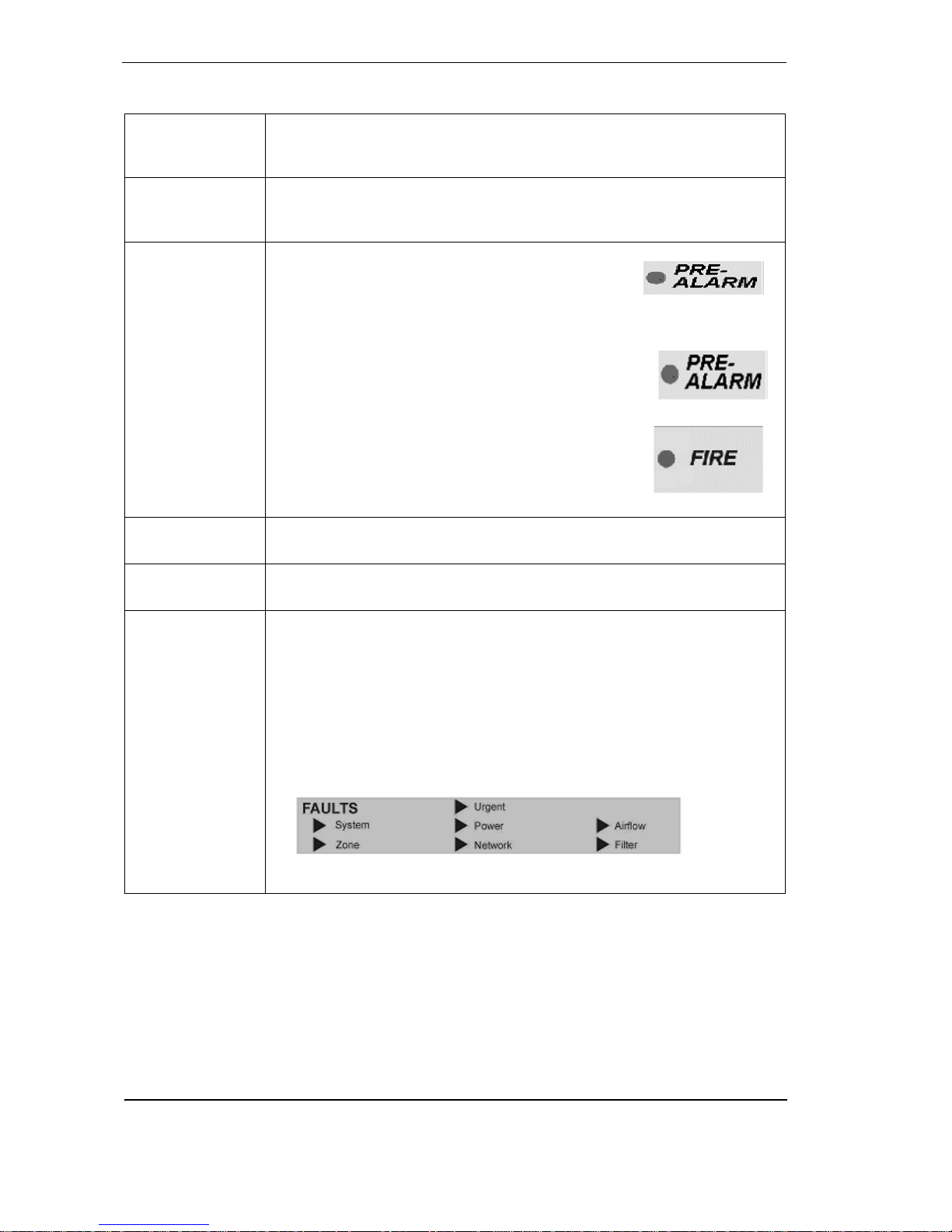
Alarm Levels
ALERT: When illuminated this LED indicates that the
smoke level is above the alert threshold. This indicates
the detector has identified very early stages of a fire
condition and/or that the smoke level in the area is
above normal.
PRE-ALARM: When lit this indicates that the detected
smoke level has passed the threshold value fixed for
Pre-Alarm, but is not intended to initiate a general fire
alarm response procedure
FIRE: When lit this indicates that there is enough
smoke to initiate a general fire alarm response
procedure. This indicates a fire may be imminent or is in
progress. When interfaced with a Fire Alarm Control
Panel (FACP) it can generate an automatic fire alarm
Bar graph
The Bar graph is a 20 step indicator where each indicator represents an
increase in the detected level of smoke, relative to the preset fire alarm level.
Threshold
Indicators
The illuminated LEDs represent visual settings for ALERT, PRE-ALARM, and
FIRE alarm levels.
Fault LEDs
Urgent - Indicates a serious fault requiring immediate attention
System - Indicates a fault in the network
Zone -Indicates a fault in the VESDA Zone monitored by the Display Module
Power - Indicates a fault in the power supply (If the GPI Function is us ed)
Network - Indicates a communications fault on VESDAnet
Airflow - Indicates abnormal air flow through the inlet pipe
Filter - This LED illuminates when the air filter requires changing
Illuminated lights showing faults.
Page 15

VESDA
®
LaserCOMPACT Product Guide
7
Push Button
Keys
These buttons enable various systems functions but can not be used to
configure the system. The Buttons can be disabled by the Systems
Administrator.
Mode/Test (Dual Function): Selects toggles between the sensitivity, smoke
level and zone number modes. When depressed for more than two seconds it
performs a light test function.
Silence: This button silences any alarm or fault warnings. It also stops the
LEDs from flashing to acknowledge a fault or alarm condition.
Reset: Resets any latched alarms and faults on the detector. Any active
alarms or faults are reported again after the time delays have elapsed.
Isolate: Isolates the detector from any external devices or systems (an isolate
alarm will normally be raised at the Fire Alarm Control Panel (FACP)).
Note: It is normal practise to signal the Isolate condition to the Fire Control
Panel using the Isolate relay
Numerical
Display
Sensitivity: Shows the level of smoke that must be measured to illuminate the
entire bar graph and always corresponds with the fire alarm level.
Smoke Level: Indicates the current level of smoke in the relevant VESDA
address and is represented as % obs/m or % obs/ft.
Zone Number: This is the VESDA Zone number assigned to the Display
Module.
Note: The Mode Button is used to select the parameters represented by the
Numeric Display (sensitivity, smoke level, zone number). The values displayed in the numerical display represent the current readings for that mode.
Page 16
LaserCOMPACT Product Guide VESDA
®
8
LCD Programmer
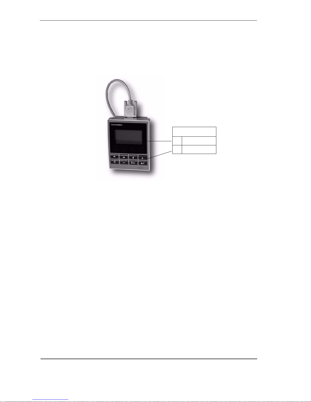
The VESDA LCD Programmer allows configuring, commissioning and maintenance of the
VESDA system. For further information please see the LCD Programmer Product Guide. A
hand-held programmer can be connected to the LaserCOMPACT VN Models (VLC-505). The
VESDAnet socket and VESDAnet terminals can be found on the termination card and can be
accessed by removing the front cover of the detector . A LCD Programmer mounted in to a remote
Unit or a 19” Sub-Rack may also be used (for VLC500 models see ‘Programming socket” on
page 22).
Figure 4 - LCD programmer
Legend
A Display
BKeys
Page 17
VESDA
®
LaserCOMPACT Product Guide
9
Product Configuration
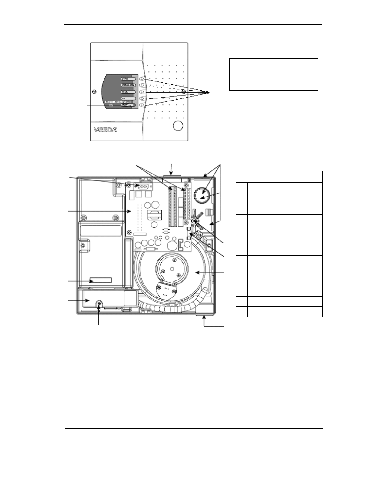
Figure 5 - Front view of the LaserCOMPACT detector
Figure 6 - View of components in the enclosures box
Legend
A Reset/Isolate Button
B LED indicators
A
B
E
F
G
H
I
J
KL
Legend
A Programming socket
15 Pin for VN model
9 Pin for RO model
B Termination card
C VESDAnet number
D Air filter cartridge
EFilter screw
F Air exhaust port
G Aspirator
H 1.6 Amp fuse
I Anti tamper screw
J Cable entry ports
K Air inlet port
L Wire terminal strips
Page 18

LaserCOMPACT Product Guide VESDA
®
10
1.4 Product Information
Product Specification
Supply Voltage 18 to 30 VDC
Power Consumption 5.4 W during normal operation, 5.9 W with alarm on
Current Consumption 225 mA at 24 VDC normal operation, 245 mA with alarm on
Fuse Rating 1.6A
Dimensions (WHD) 225 mm x 22 5 mm x 85 mm (8 7/8 in x 8 7/8 in x 3 3/8 in)
Weight 1.9kg (4.2 lbs)
Operating Temperature
(To operate the
LaserCOMPACT detector
outside these parameters
please contact your
nearest VESDA Office)
Detector Ambient:
UL tested: 0° to 39° C (32° F to 103° F)
Sampled Air: -20° to 60° C (-4° to 140° F)
Humidity: 10-95% RH, non-condensing
Storage Temperatures
(Non-operational)
Up to 2 years (battery life). 0° to 85° C
Dry (<95% humidity),
0° to 85° C,
Must not exposed to sunlight or other radiation sources
Sampling Pipe Network
Maximum area of coverage: 800 m
2
(8000 sq. ft.)
Maximum Single Pipe Length: 80 m (max. 20 holes)
Maximum branched (2) Pipe Lengths: 50 m each (max. 20 holes)
Computer Design Tool: ASPIRE™
Pipe Size ID: 15-21 mm (0.874 in)
OD: 25 mm (1.050 in.)
Relays 3 relays, contacts rated 2A @ 30 VDC
Programmable to latched or non-latched states
Relays Default
Configuration
Fire
Pre-Alarm
Alert/Fault (Maintenance and Isolate)
Programmable 0 - 60 sec. time delay for each relay
IP Rating IP30
Cable Access 4 x 25 mm (1 in) cable entries
Cable Termination Screw terminal blocks (0.2-2.5 sq mm, 30-12 AWG)
Detector Resolution 0.005 to 20.00% obs/m
(0.0015 to 6.25% obs/ft.)
Page 19

VESDA
®
LaserCOMPACT Product Guide
11
Table 2 - LaserCOMPACT detector specifications
Threshold Setting Range Alert: 0.005 - 1.990% obs/m
(0.0015 - 0.6218% obs/ft.)
Pre-Alarm: 0.010 -1.995% obs/m
(0.0031 - 0.6234% obs/ft.)
Fire: 0.015 - 20% obs/m
(0.0046 - 6.25% obs/ft.) **
**Factory Default = UL268 = Fire set to 12% obs/m (4% obs/ft.) to
comply with UL268). If the factory default is off the fire threshold can
be set up to 20% obs/m (6.25% /ft.)
Key Software Features Event log: Up to 12000 events stored on FIFO basis.
(Volatile Event Log) Smoke level, alarms and faults with time and
date stamp
AutoLearn: Minimum 15 minutes, maximum 15 days.
(Recommended minimum period 14 days).
During AutoLearn thresholds are NOT chan g ed from pr e- se t valu es .
Page 20
LaserCOMPACT Product Guide VESDA
®
12
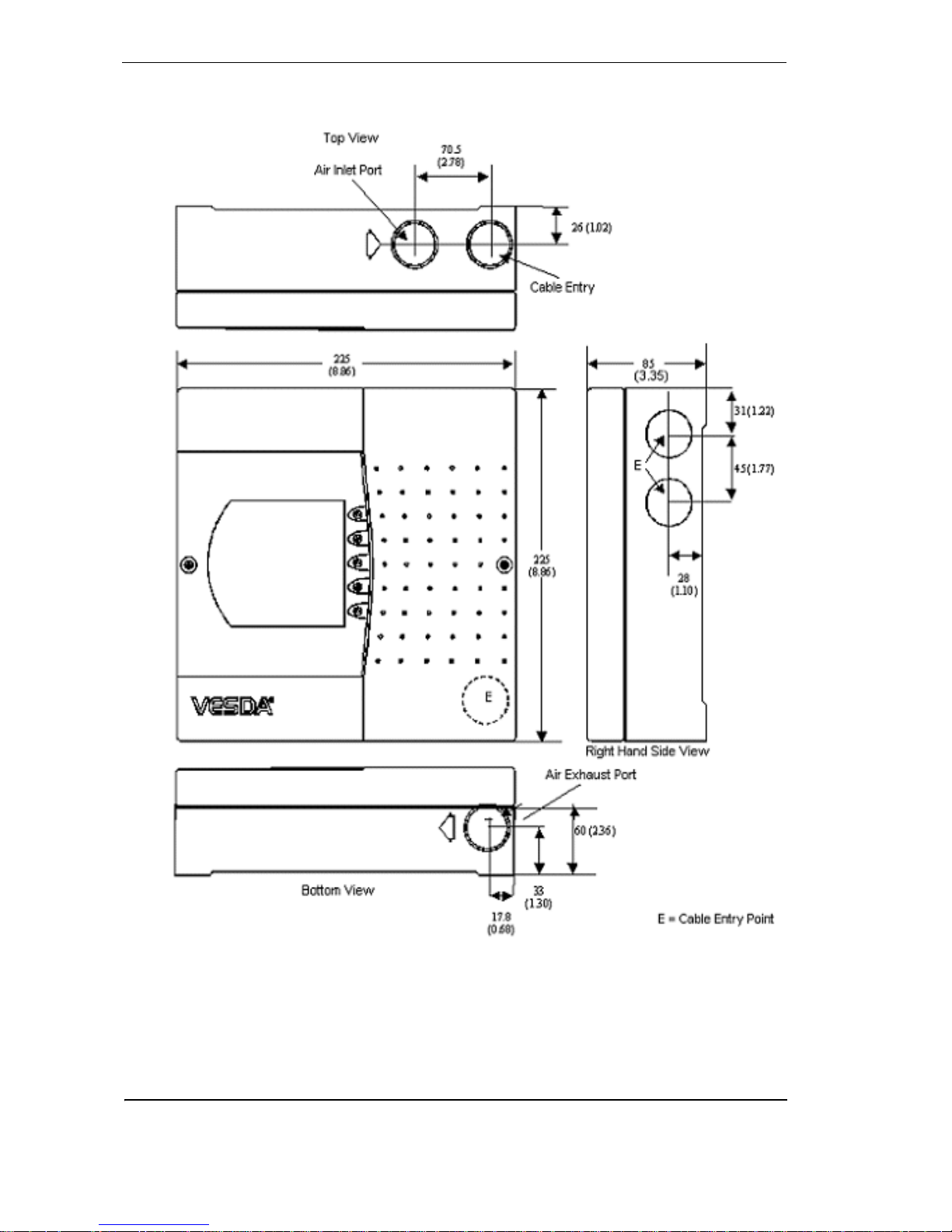
Product Dimensions
Figure 7 - Dimensions in mm. (inches) for LaserCOMPACT
Page 21
VESDA
®
LaserCOMPACT Product Guide
13
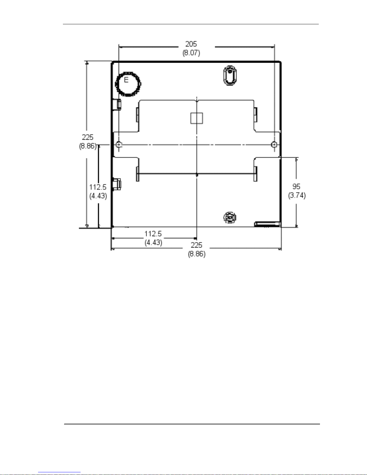
Figure 9 - LaserCOMPACT detector dimensions - rear view
E = Cable Entry Port on rear of enclosure
Page 22

LaserCOMPACT Product Guide VESDA
®
14
Default Settings
Table 3 - Default values for the LaserCOMPACT detector
Parameter Default Value
Range Minimum
Access
Level
Minimum Maximum
Event Log - Events
• Smoke Level Enabled N/A N/A Adm
• Alarms Enabled N/A N/A Adm
• Faults Enabled N/A N/A Adm
• User Action Enabled N/A N/A Adm
Fire Threshold 0.2% obs/m
(0.062% obs/ft.)
0.015% obs/m
(0.0046% obs/ft.)
20% obs/m
(6.25% obs/ft.)
Adm
Pre-Alarm Threshold 0.14% obs/m
(0.044% obs/ft.)
0.010% obs/m
(0.0031 obs/ft.)
1.995% obs/m
(0.6234% obs/ft.)
Adm
Alert Threshold 0.08% obs/m
(0.025% obs/ft.)
0.005% obs/m
(0.0015 obs/ft.)
1.990% obs/m
(0.6218% obs/ft.)
Adm
Alarm Delays…Fire 10 seconds 0 seconds 60 seconds Adm
Alarm Delays…Pre-Alarm 10 seconds 0 seconds 60 seconds Adm
Alarm Delays…Alert 10 seconds 0 seconds 60 seconds Adm
Delay Times Simultaneous Simultaneous Cumulative Adm
Instantaneous - Fire Disabled N/A N/A Adm
AutoLearn 14 days
0 Hours
0 Minutes
0 Days
0 Hours
15 minutes
15 days
23 Hours
59 Minutes
Adm
Adm
Adm
Air flow Thresholds:
• High Urgent
• High Minor
• Low Minor
• Low Urgent
130%
120%
80%
70%
105%
105%
25%
25%
200%
200%
95%
95%
Adm
Adm
Adm
Adm
Communications:
• Open-ended loop
• Preferred Port
• N etwork Delay
• Health Check
None
A
15 seconds
45 seconds
N/A
N/A
10 seconds
40 seconds
N/A
N/A
45 seconds
60 seconds
Adm
Dst
Dst
Dst
Device ID Name/Location N/A N/A Adm
Faults Latched Latche d N/A N/A Adm
Filter Service Interval 1825 days (5
years)
1 day
(Dependent up
on environment)
1825 days
(5 years)
Adm
Page 23

VESDA
®
LaserCOMPACT Product Guide
15
Note: UL Specs: To meet UL specifications, any alarm thresholds that initiates an
evacuation procedure via a Fire Alarm Panel must not be set higher than 2% obs/m
(0.625% obs/ft.)
Relay settings and conditions to change states
Table 4 - Default relay settings and conditions to change state
Auxiliary / GPI Terminals
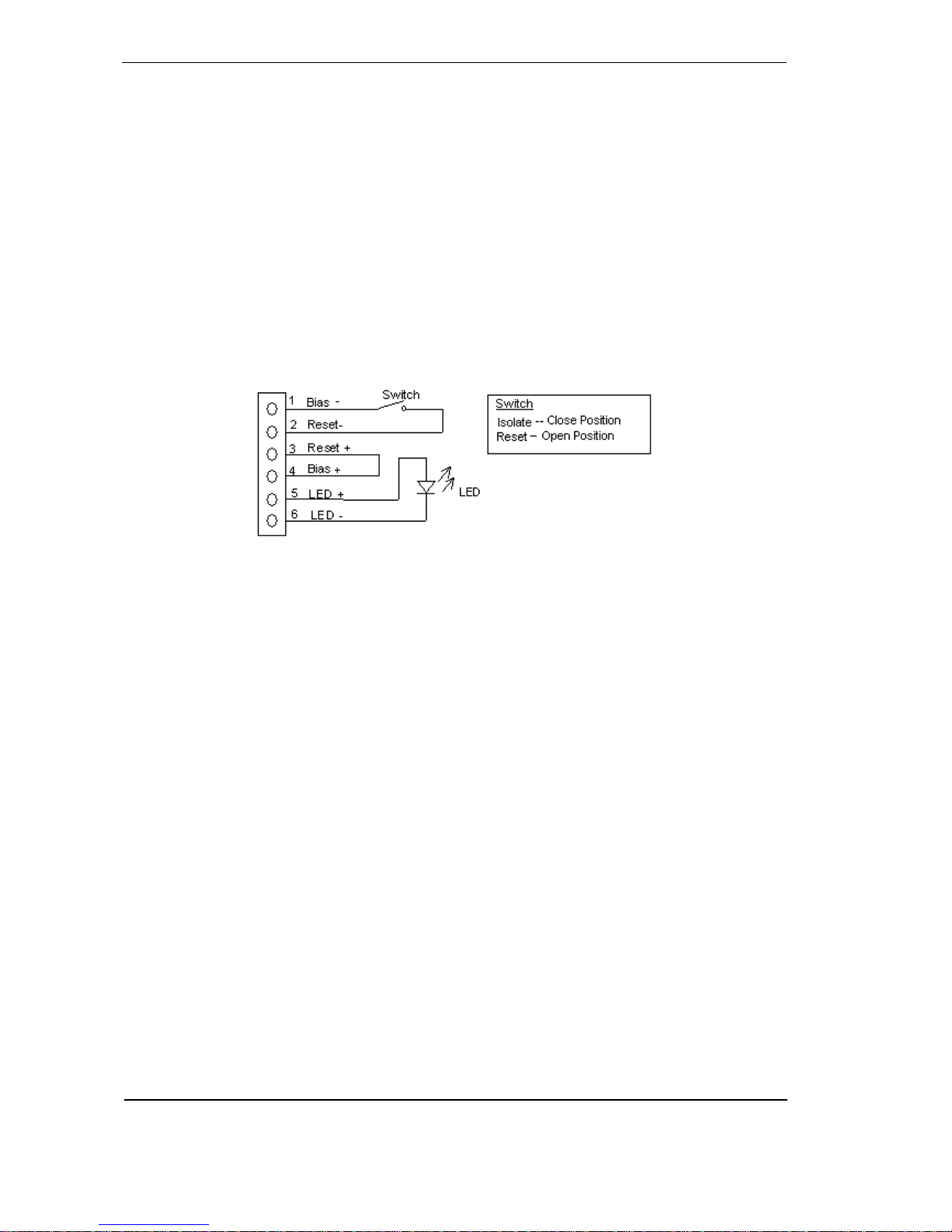
The Bias, Reset (GPI) and LED terminals are located on the termination card (Refer to
Figure 14, “LaserCOMPACT termination card VN Model (VLC-505),” on page 19 and Figure 15,
“LaserCOMPACT termination card RO Model (VLC-500),” on page 20. These terminals have the
following functions:
Bias Terminals: These output terminals provide 10 VDC supply to initiate the reset inpu t
terminals via a remote reset/isolate switch.
LED T erminals: These output terminals provide a 5 V, 15 mA DC supply via a 220 ohm resistor
to power a remote LED.
Reset (GPI) Terminals: These terminals are also known as the General Purpose Input (GPI)
and are used for Reset, Mains OK or Standby functions. The input terminal requires a voltage
supply between 5 V and 24 VDC to operate. The volt age input to th is terminal is isol ated from the
system by an opto-coupler device. Connect the Reset (+) terminal to the positive output and the
Reset (-) terminal to the ground output of the external device (for an example of use refer to
Figure 21, “Wire connection details for power terminals on VN and RO model termination card ,”
on page 24).
Relay # Relay Condition for relay to change state
1 Fault This relay is de-energized when one of the following conditions occur:
Fault found on detector or on VESDAnet loop
Air flow normalization is initiated
System isolation is initiated
When the Overlay Alert function has been selected, this relay is de-
energized once the Alert Threshold is initiated
2 Pre-Alarm This relay is energized once the Pre-Alarm threshold is initiated
3 Fire This relay is energized once Fire Alarm threshold is initiated
Page 24
LaserCOMPACT Product Guide VESDA
®
16
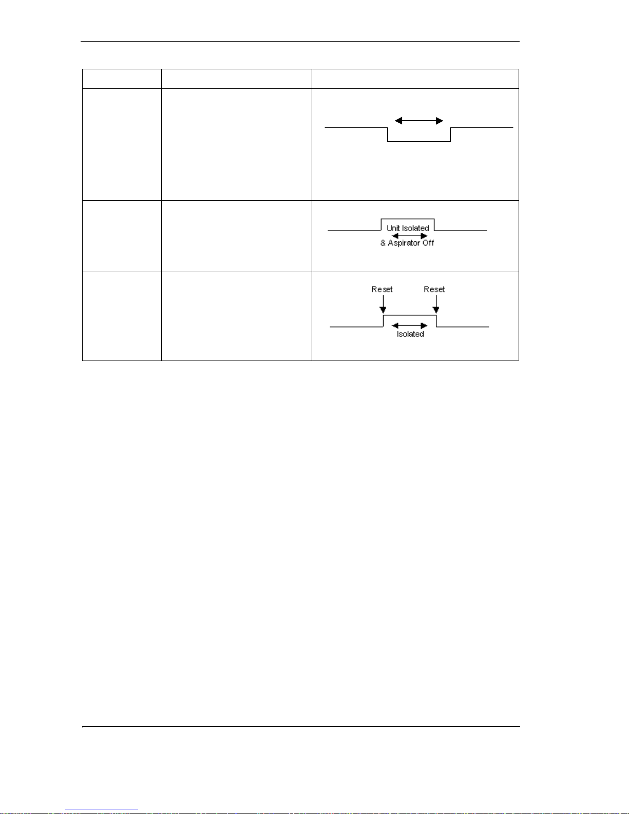
Table 5 - GPI functions
1.5 Mounting the Detector
The VESDA LaserCOMPACT can be mounted onto the wall using the mounting bracket on any
suitable secure surface.
Note: The detector can only be mounted using the mounting bracket included with the
packaging.
Function State change
Mains OK The detector monitors the state
of the external power supply and
responds to the following
conditions.
Mains OK ≥ 5 VDC is at this
terminal
Mains Fail ≤ 2 VDC is at this
terminal
Standby Mode The detector Isolates and the
aspirator turns OFF when ≥
5 VDC is at this terminal
Note: No Alarms can be generated in this state
Reset Isolate While power is applied to the
GPI the detector is isolated. In
addition, the connection of
power to the GPI resets the unit.
≥ 5 VDC Detector Isolates
≤ 2 VDC Detector Reset
Mains Fault Reported
Page 25
VESDA
®
LaserCOMPACT Product Guide
17
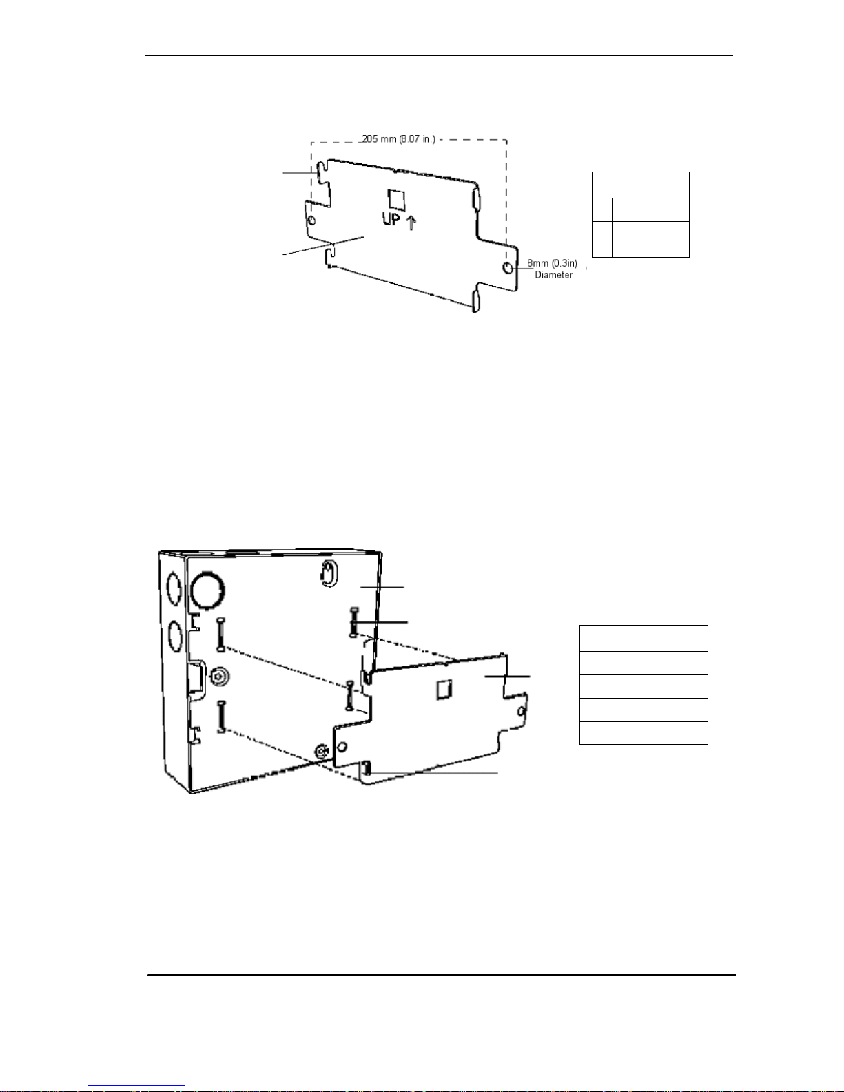
Securing the mounting bracket
The mounting bracket for the VESDA LaserCOMPACT is always mounted in the UP direction.
The mounting bracket is clearly marked with the word “UP” and an upward poin ting arrow.
Figure 10 - The mounting bracket for normal and inverted orientations
Secure the mounting bracket to the surface using appropriate fasteners, ensuring that the
bracket is horizontally straight and sits flush on the surface.
Determine the ports for cable entry. Press out the tabs for the cable entry , a ir inlet and air exhaust
ports.
Installing the Detector
Determine the orientation for mounting the LaserCOMPACT detector. Remove the front cover
and if necessary separate it from the enclosure box. The back of the enclosure box is slotted
over the four mounting bracket tabs. Slide the detector downwards until it slides onto the tabs.
Screw in the anti-tamper screw. Check to confirm that the detector does not slide off the
mounting bracket.
Figure 1 1 - Mounting the LaserCOMPACT detector onto the mounting bracket
B
A
Legend
ATab
B This side to
detector
A
B
C
D
Legend
A Back of Detector
B Rectangle Slots
C Mounting Bracket
D Bracket Tab
Page 26
LaserCOMPACT Product Guide VESDA
®
18
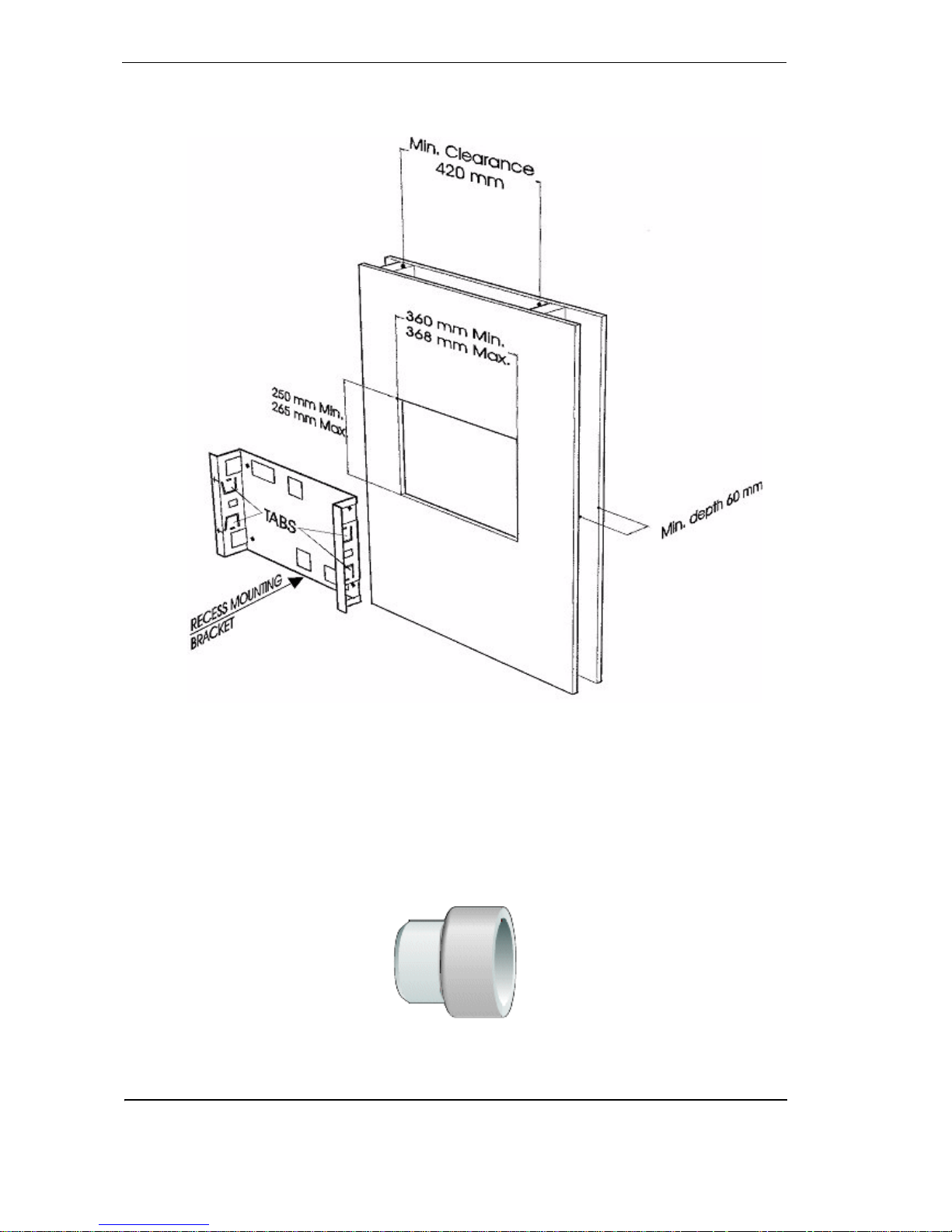
Recess mounting kit
These kits are used to house a detector inside a wall cavity.
Figure 12 - Recess mounting kit
1.6 Connecting the VCL to the Pipe Network
Inlet Pipes
The air inlet port is designed to fit a standard pipe of 25 mm (1 in) OD. A 25 mm to 1.050 inches
adaptor is included for all USA shipments to fit the Pipe Inlet.
Figure 13 - Pipe reducer
Page 27
VESDA
®
LaserCOMPACT Product Guide
19
The Air Inlet Port allows the pipe to be inserted up to 1 5 mm (0.60 in). To connect the detector to
the Pipe Network:
1. Ensure a minimum length of 500 mm (20 in) of straight pipe before terminating the pipe at
the air inlet port of the detector.
2. Square off and de-burr the end of the sampling air pipe, ensuring the pipe is free from swa rf.
3. Insert the pipe into the inlet port ensuring a firm fit. DO NOT glue the inlet pipes to the Pipe
Inlet Manifold.
Air Exhaust Pipe
Unplug the air exhaust port at the bottom of the detector. If necessary pipe the exhaust back to
the relevant VESDA Zone. The maximum suggested length for the exhaust pipe is 4 m (13 ft.)
1.7 Wiring Connections
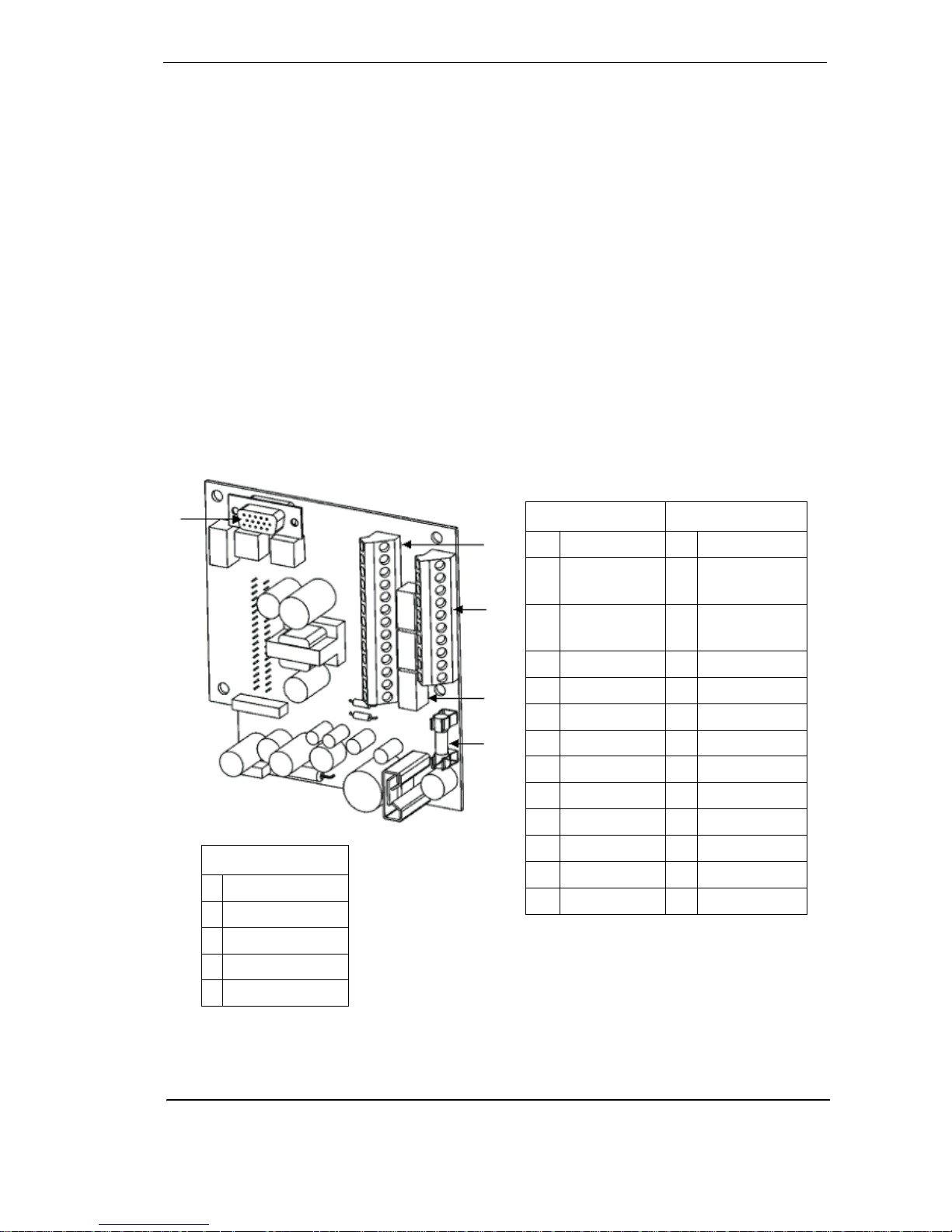
Termination Card
The Termination Card acts as the interface for VESDAnet (VN Model), VESDA Link (RO Model),
power supply Terminals, relay and relay Terminals.
Figure 14 - LaserCOMPACT termination card VN Model (VLC-505)
NC = Normally Close
NO = Normally Open
C = Common
Terminal A Terminal B
1 Bias (-) (GND) 1 Shield
2 Reset (-)
(GPI)
2 VESDAnet A (-)
3 Reset (+)
(GPI)
3 VESDAnet A (+)
4 Bias (+) 4 Shield
5 LED (-) (GND) 5 VESDAnet B (-)
6 LED (+) 6 VESDAnet B (+)
7 FIRE (NO) 7 Power (-)
8 Fire (C) 8 Power (+)
9 Pre-Alarm (NO) 9 Power (-)
10 Pre-Alarm (C) 10 Power (+)
11 Fault (NO)
12 Fault (C)
13 Fault (NC)
A
B
C
D
Legend
A Terminal A
B Terminal B
C Relays
D 1.6 Amp Fuse
E VESDAnet Socket
Page 28
LaserCOMPACT Product Guide VESDA
®
20
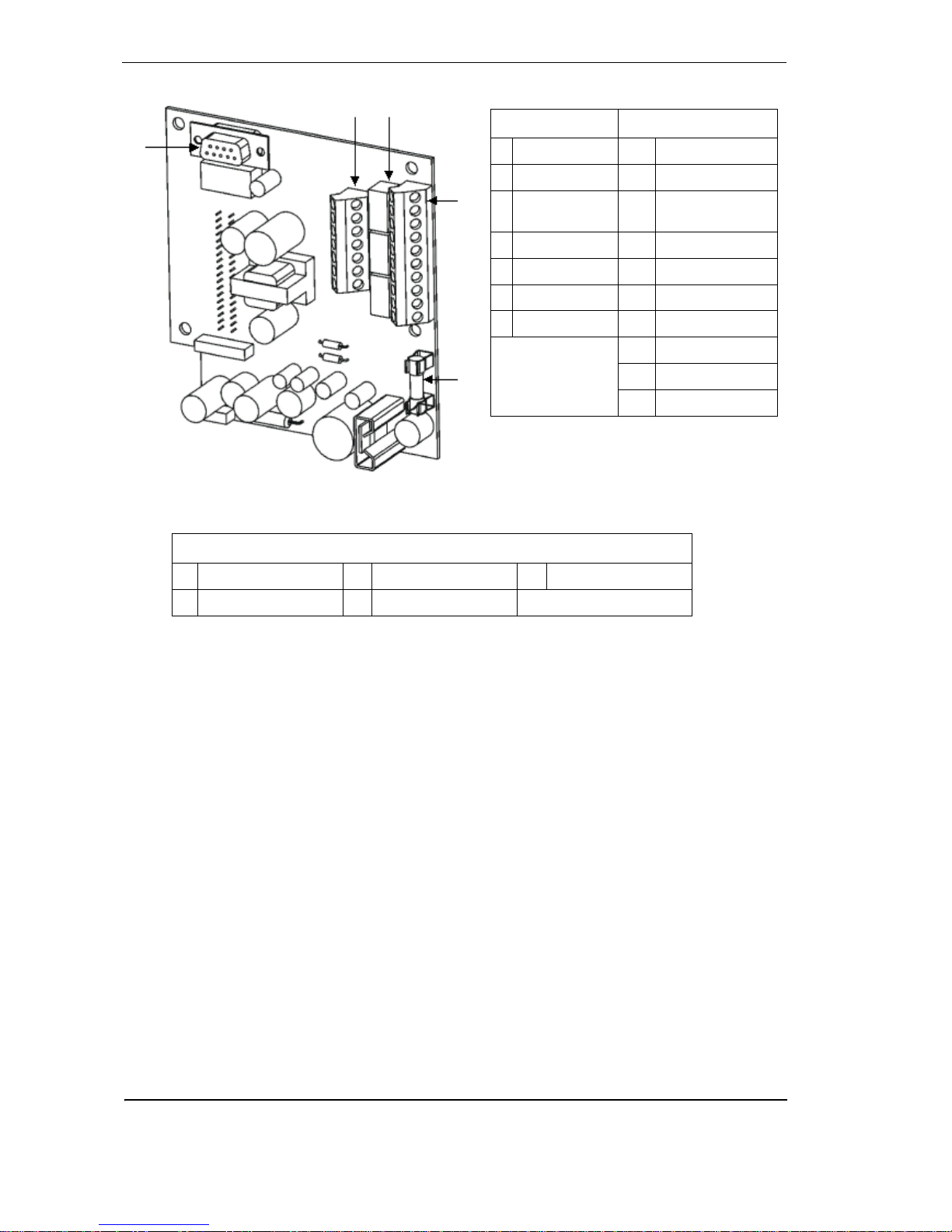
Figure 15 - LaserCOMPACT termination card RO Model (VLC-500)
LEGEND
A Terminal A C Relays E VESDAlink Socket
B Terminal B D 1.6 Amp Fuse
Terminal A Terminal B
1 FIRE (NO) 1 Bias (-) (GND)
2 Fire (C) 2 Reset (-) (GPI)
3PRE-ALARM
(NO)
3 Reset (+) (GPI)
4 PRE-ALARM (C) 4 Bias (+)
5 FAULT (NO) 5 LED (-) (GND)
6FAULT (C) 6 LED (+)
7 FAULT (NC) 7 Power (-)
8 Power (+)
9 Power (-)
10 Power (+)
NC = Normally Closed
NO = Normally Open
C = Common
E
AC
B
D
E
Page 29
VESDA
®
LaserCOMPACT Product Guide
21
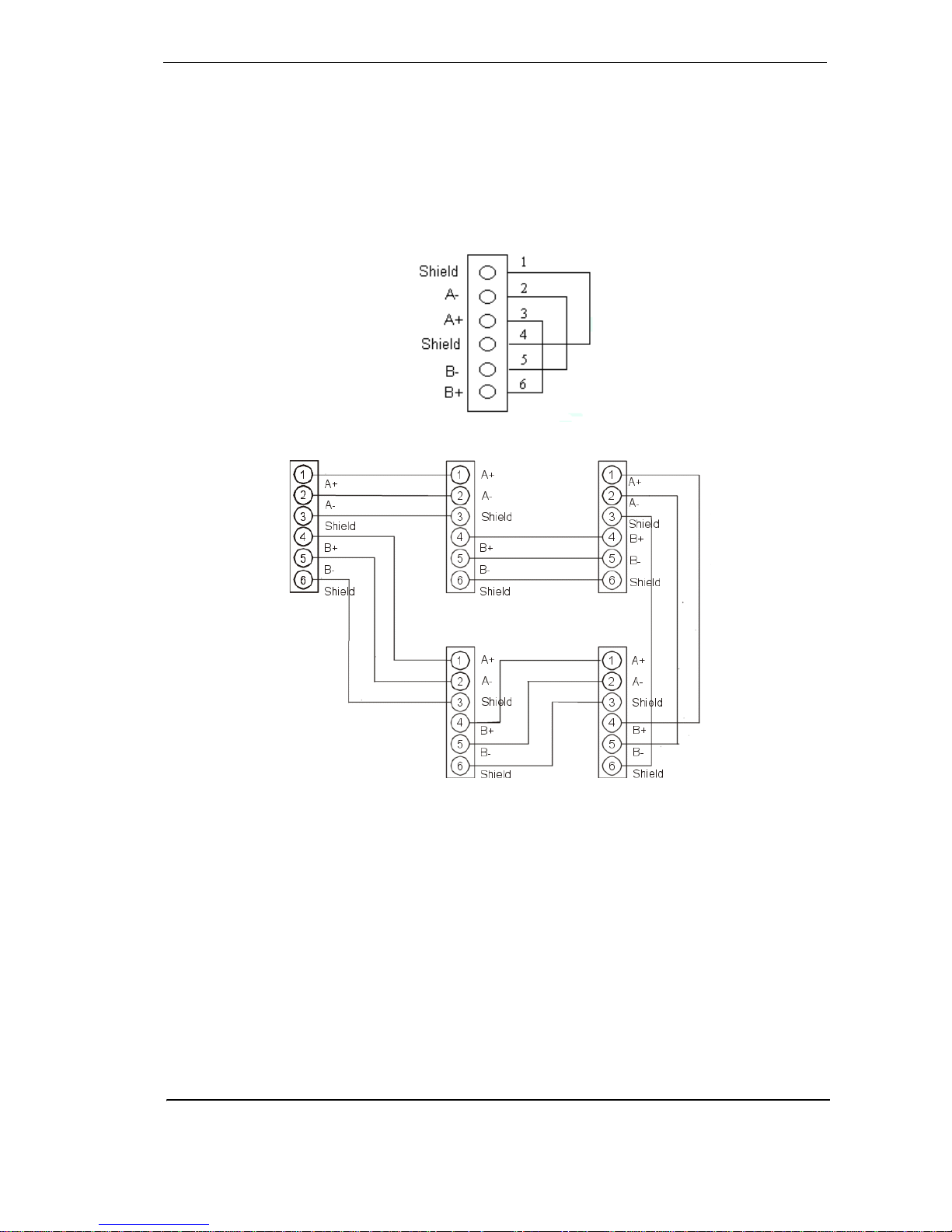
VESDAnet Terminals (VN Model only):
The LaserCOMPACT detector can be connected to VESDAnet through VESDAnet Terminals on
the Termination Card. The terminals enable VESDAnet communication cables to be brought into
the detector and then looped out to another device. Data communication between the detector
and other devices on VESDAnet are bidirectional. The polarity of the data wires must be
maintained throughout the network. It is recommended that RS 485 (BELDEN 9841 - 120 Ohm)
twisted pair cables (or similar) be used. The LaserCOMP ACT is shipped without the VESDAnet A
and B channels looped. If the detector is not to be networked with other devices, then loop the A
and B channels.
Figure 16 - Stand -alone VESDAnet connection for LaserCOMPACT
Figure 17 - An example of the wire connection for VESDAnet
(closed loop)
Relay terminals
There are three relays designated Fault, Pre-Alarm and Fi re . The rela ys ca n be used to conne ct
to the fire alarm control panel or to activate external devices. The default relay states are nonenergized except the fault relay, which is set to the energized state on power up. The relays can
be programmed to either state.
Page 30
LaserCOMPACT Product Guide VESDA
®
22
Programming socket
The 15 pin or 9 pin programming socket on the termination card provides the communication
interface between the detector and a LCD Programmer or PC. Use the information listed below
to determine the type of programming device required to program the VN or the RO detector.
• VN model: The programming socket on the termination card has 15 pins. Use a LCD
Programmer and connect the programmer cable to the 15 pin VESDAnet programming
socket.
OR
• Use a PC with a VESDA PC-Link HLI and the appropriate data cables to connect to the 15
pin VESDAnet programming socket.
• RO model: The programming socket on the termination card has 9 pi ns. The RO mode l
is programmed using a PC Software. Connect the PC to the detector using a RS232 data
cable directly to the 9 pin VESDAlink programming socket.
Auxiliary / GPI Terminals:
Figure 18 - Wire connection for Auxiliary / GPI Terminals
Page 31
VESDA
®
LaserCOMPACT Product Guide
23
For further information see Auxiliary / GPI Terminals on page 15
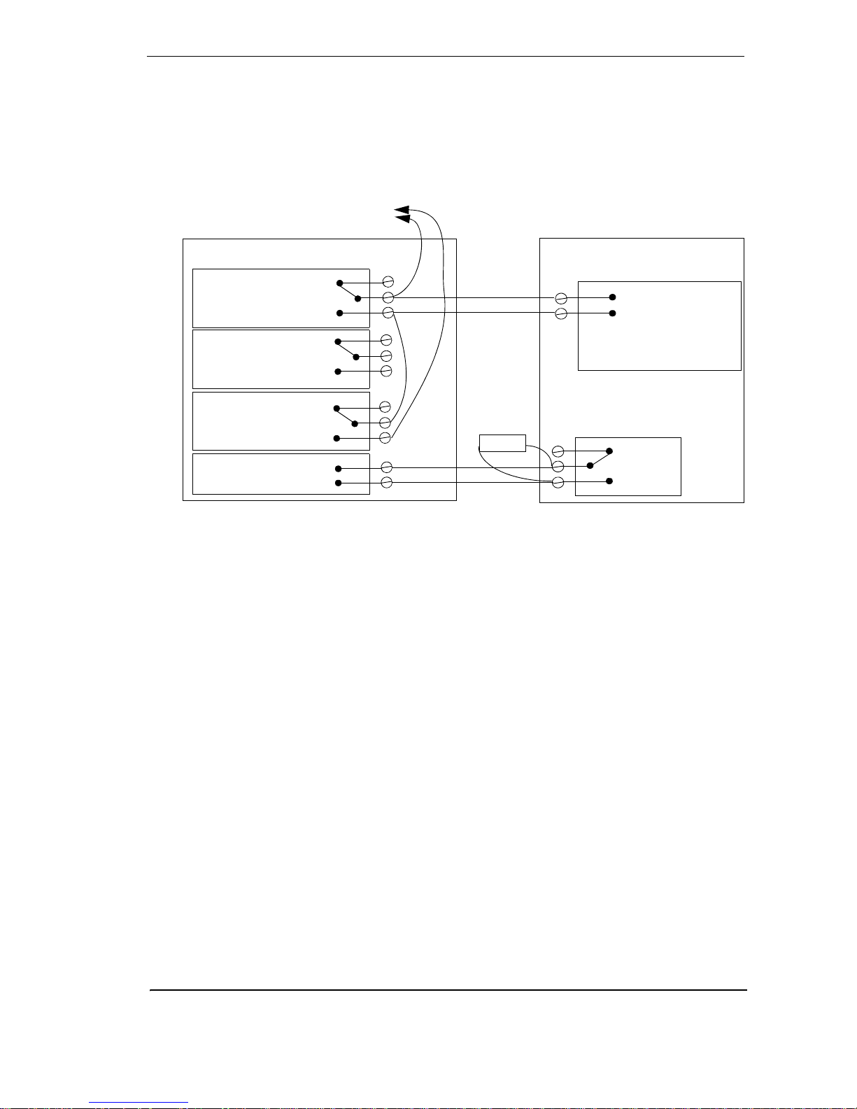
Typical Wiring To Fire Alarm Control Panel (FACP)
The diagram below shows the correct way to wire VESDA laser detectors to a conventional fire
alarm control panel (FACP). It also shows where an End Of Line (EOL) resistor is correctly
installed.
Figure 19 - Typical wiring to a fire panel with EOL
Normally Closed (NC)
FIRE 1 Common (C)
Normally Open (NO)
Normally Closed (NC)
ACTION Common (C)
Normally Open (NO)
Normally Closed (NC)
FAULT Common (C)
Normally Open (NO)
GPI
(Set to reset)
(NC)
Reset (C)
(NO)
Input
Short = Fire
Open = Fault
Fire Panel (FACP)
Detector
EOL
To next detector
or EOL resistor
Page 32
LaserCOMPACT Product Guide VESDA
®
24
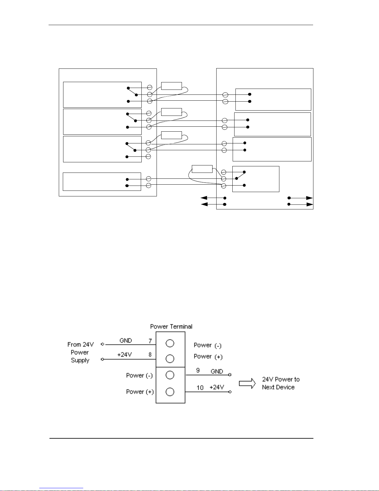
Wiring To an Address Loop Module.
This wiring example is for wiring VESDA detectors to a typical Address Loop module 3 input 1
output. These are example drawings. Refer to the appropriate product manual for the exact
wiring details of the third party equipment.
Figure 20 - Addressable Loop Module with EOL
1.8 Power source
The power terminals on the termination card connect to a 24 VDC power supply. The four power
terminals enable power to be brought into the de tector via and looped out to anoth er device. The
detector has reverse polarity protection to minimize the risk of reverse power connection to the
detector.
Note: The LaserCOMPACT detector will not operate when the power supply is reversed.
Note: Operating the detector outside the DC supply voltage range of 18 VDC and 30 VDC
may cause damage to the device.
Figure 21 - Wire connection details for power termina ls on VN and RO mod el
termination card
Normally Closed (NC)
FIRE 1 Common (C)
Normally Open (NO)
Normally Closed (NC)
ACTION Common (C)
Normally Open (NO)
Normally Closed (NC)
FAULT Common (C)
Normally Open (NO)
GPI
(Set to reset)
(NC)
Reset (C)
(NO)
Fire Input
Short = Fire
Open = Wiring Fault
3 output 1 input Loop Module
Detector
EOL
Pre Alarm
Short = Fire
Open = Wiring Fault
Fault Input
Short= Detector Fault
Open = Wiring Fault
EOL
EOL
EOL
To Next Detector
To FACP
Page 33

VESDA
®
LaserCOMPACT Product Guide
25
1.9 Battery Back Up
The power supply for the LaserCOMPACT detector may be switched to a back up battery in the
event of the supply being disrupted. The size of the battery back up is determined by local
standards and codes, the total power required by the system, back up time required, allowance
for reduction in capacity with age and expected temperature variations.
Note: It is recommended that batteries be changed as per the battery manufacturer’s
specifications or as per your local codes and standards.
Backup battery size calculation sheet
Table 6 - Calculating the size of backup battery
1.10 Starting Up
Note: A LaserCOMPACT detector must be powered up by VESDA accredited personnel
only
Normal load @ 24 V DC Full alarm load @ 24 V DC
Equipment Load mA Number Total Load mA Number Total
Detector @ 2490 rpm 170 190
Remote Display 90 110
Remote Programmer 50
(backlight off)
110
(backlight on)
Hand-held
Programmer
50
(backlight off)
110
(backlight on)
Other 24 V loads
Total mA Total mA
XX
Standby hours Alarm hours
=
Standby capacity Alarm capacity
Total capacity = Standby + Alarm capacity
Divided by 1000 for standby capacity
Multiplied by battery factor (Normally 1.25)
Page 34

LaserCOMPACT Product Guide VESDA
®
26
After installing the LaserCOMPACT detector it is necessary to power up the system. The system
takes approximately 15 seconds to power up. If the system fails to power up, check all power
wires are secured to its terminals and the polarities of the power wires are correctly terminated.
On power up:
• The aspirator starts up
• The LED indicators on the LaserCOMPACT front cover:
- Will light up and cycle on and off
- If a fault has been detected the FAULT LED indicator will remain lit
- If the system is functioning normally the OK LED indicator will remain lit
• If a Remote Display Module is connected the following indicators are lit:
- Fire alarm threshold indicators
- Smoke threshold levels on bar graph
- Two digit numerical display
- Various fault indicators if there are any faults
- System OK indicator if there are no faults
If any of the above does not happen, contact your commissioning engineer or distributor to
troubleshoot.
Note: It is normal for the detector to display troubles immediately after power up. Reset
the detector by pressing the reset button on th e front cover of the detector to unlatch
the relays and fault LEDs. The fault LEDs on the front cover will illuminate. Proceed
with the preliminary systems check.
Page 35

VESDA
®
LaserCOMPACT Product Guide
27
Installation Checklist
Perform the following checks listed below to ensure that all the necessary items are completed
before handing over to a commissioning engineer.
Table 7 - Installation Checklist
Site Name
Address
Detector Serial Number(s)
and Date of Manufacture
Interface Card Serial
Number & Date of
Manufacture
Name of Installer
Signature
Date
INSTALLATION CHECKS Yes No
1. Were the detector and the mounting bracket intact in the box?
2. Is the detector securely locked onto its mounting bracket? Note
that the two mounting bracket securing-scre ws ar e pr ov ide d in a
separate bag with the detector.
3. Is the sampling air pipe firmly connected to the air inlet port?
Ensure the pipe is NOT
glued.
4. Have the power wires been connected to the correct terminals on
the detector?
5. If required, has the end of line resistor been connected?
6. Have the alarm signalling wires been terminated to the correct
terminals of the detector?
7. Has the Interface card been correctly installed according to the
instructions provided (if applicable)?
8. Has the plug at the exhaust port been removed and the exhaust
pipe (if fitted) not glued?
9. Has the front cover been replaced correctly?
10.Has AutoLearn Flow and AutoLearn Smoke been performed?
Please state the AutoLearn Smoke period____________
1 1.Is the air sampling pipework installe d and checked as per the site
plans?
Page 36
LaserCOMPACT Product Guide VESDA
®
28
1.11 Preliminary Systems Check
A preliminary systems check is required after installing the LaserCOMPACT detector, before it is
commissioned for use. The check can be conducted by connecting the detector to a LCD
Programmer or using VSC, or VSM4 PC based software. The preliminary system s check
includes:
• Conducting a VESDAnet communications check
• Accepting factory default configurations, or changing to site requirements
• Normalizing the air flow
• Conducting a basic pass/fail smoke test
For details on preliminary systems check refer to the LCD Programmer or the relevant software
manuals. Refer to the VESDA LCD Programmer and Commissioning Guides for further details.
1.12 Maintaining and Servicing the Detector
To maintain the LaserCOMPACT detector at its peak performance the maintenance schedule
given below should be followed. Maintenance can be conducted by the original installer, a
VESDA distributor, or a service contractor. To work effectively the LaserCOMPACT detector
needs to be supported by a well designed pipe network. The VESDA Maintenance Manual
contains a schedule for pipe network maintenance.More frequent maintenance may be
necessary for harsh environments or be required by your local fire authority.
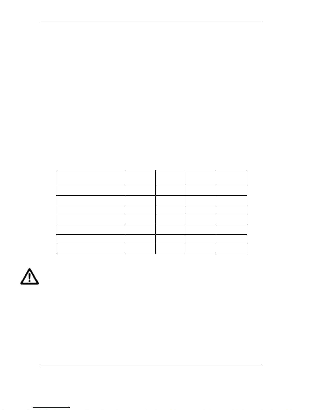
Table 8 - Maintenance schedule for LaserCOMPACT detector
Caution: When a VESDA detector has been isolated, no fire warnings will be issued by the
VESDA LaserCOMPACT and any fire will go undetected. Prior to any maintenance
or testing:
Note: Inform appropriate supervising authority about the risk associated with isolating a
VESDA address (formerly known as a VESDA Zone).
Note: Ensure that any ancillary devices dependent on the VESDA LaserCOMPACT is/are
isolated before work is begun.
Maintenance Check Quarterly
Six
Monthly
Annual
Every T wo
Years
Power Supply X
Check Pipe Network X
Filter Inspection X
Pipe Integrity Smoke Test X
Check Pipe Flow X
Clean Sampling Point. X
Flush Pipe Network X
Page 37
VESDA
®
LaserCOMPACT Product Guide
29
Opening and Closing the detector
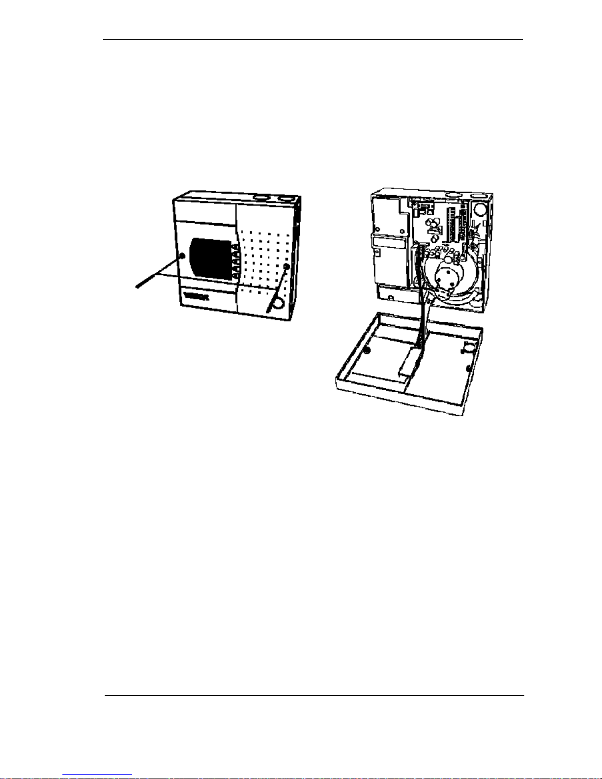
Opening the detector
1. Undo the two screws on front cover
2. Open the front cover and allow cover to hang by the attached plastic strap
Closing the detector
1. Replace the front cover over detector enclosure ensuring the plastic strap and cable loom
are not wedged between the cover and enclosure
2. Tighten the two screw
Figure 22 - Opening and closing a LaserCOMPACT detector
Page 38
LaserCOMPACT Product Guide VESDA
®
30
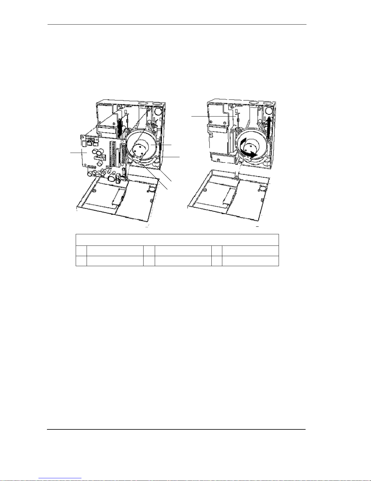
Replacing the aspirator
1. Remove the 4 screws securing the termination card (A)
2. Disconnect the wires on the aspirator (B)
3. Gently pull out termination card (A) from the interface card (Y ou can’t see the interface card,
it is connected to the back of the termination card). Leave the termination card suspended
by its wires.
4. Pull off the air hose from aspirator pipe (C)
5. Undo the (captive) screws securing aspirator (D)
6. Lift the aspirator out
Figure 23 - Illustration for replacing the aspirator
Assembly
1. Put the aspirator pipe inlet into the hole leading to the pipe network (E)
2. Tighten the screws securing the aspirator (D)
3. Connect the air hose to the aspirator pipe (C). Ensure a tight fit over the pipe.
4. Insert the termination card (A) into the interface card slot (F)
5. Tighten the termination card screws (A)
6. Reconnect the wires to the aspirator (B)
7. Put the front cover back on and tighten the screws
8. Power ON the detector and check the aspirator is running
9. Resolve all Fault conditions
LEGEND
A Terminal card C Aspirator air hose E Pipe network port
B Aspirator wire loom D Aspirator F Interface card slot
A
B
C
D
E
F
Page 39

VESDA
®
LaserCOMPACT Product Guide
31
Internal wiring for LaserCOMPACT
The table below provides the cable loom interconnecting det ails inside the de tector. Use the look
up table in conjunction with the attached circuit diagram to assist with maintenance.
Table 9 - Interconnecting loom details
1.13 Spare Parts
On larger sites having multiple detectors it is advisable to stock certain critical spare parts. A list
of spare parts with quantities required is given below:
Table 10 - Recommended spare parts stock
From To
Connector
Name on CPU
Cable Name # Pins
CPU card Detection chamber Pre-amp or X9 Pre Amp 6 Wire ribbon
CPU card Detection chamber Laser or X10 Laser 6
Termination
card
LED PCB LED card or X11 LED cable 7
Termination
card
Aspirator Aspirator or X12 Aspirator
cable
3
Part No. Description
Number of detectors Installed
to warrant ONE Spare Part
Normal
Service
Mission
Critical
VSP-005 Filter Cartridge 50 20
VSP-501 LaserCOMPACT Aspirator N/A 20
VSP-502 LaserCOMPACT VN Remote Display Module 50 20
VSP-510 LaserCOMPACT RO Termination Card (CTC-RO) 50 20
VSP-515 LaserCOMPACT VN Termination Card (CTC-VN) 50 20
Page 40

LaserCOMPACT Product Guide VESDA
®
32
Page 41

VESDA
®
LaserCOMPACT Product Guide
33
Index
A
Air Exhaust Pipe.................................. 19
Air flow Thresholds.............................. 14
Alert Threshold.................................... 14
Aspirator............................................... 2
Aspirator assembly.............................. 30
Aspirator replacement.......................... 30
B
Battery Back Up................................... 25
Bias Terminals..................................... 15
C
Check Pipe Flow.................................. 28
Check Pipe Network............................. 28
Clean Sampling Point........................... 28
Configurations of LaserCOMPACT........... 1
Contact Us............................................ ii
Conventions........................................... i
D
Default Settings ................................... 14
Delay Times ........................................ 14
Detection chamber................................. 3
Detector Chamber.................................. 2
Device ID ............................................ 14
F
Fault
Airflow
............................................. 6
Filter................................................ 6
Network ........................................... 6
Power.............................................. 6
System ............................................ 6
Urgent ............................................. 6
Zone................................................ 6
Fault lights.......................................... 26
Fault Relay Settings............................. 15
Faults Latched..................................... 14
Filter Inspection................................... 28
Filter Service Interval ........................... 14
Fire light ............................................... 6
Fire Relay Setting ................................ 15
Fire Threshold..................................... 14
First Stage Air Filter............................... 2
Flush Pipe Network.............................. 28
H
High Minor .......................................... 14
High Urgent......................................... 14
I
Inlet Pipes........................................... 18
Internal Wiring..................................... 31
Introduction to LaserCOMPACT Detector
LaserCOMPACT Remote Box Display Module
5
Isolate button........................................ 7
Isolate LED ........................................... 6
L
Laser detection chamber ........................ 3
LaserCOMPACT
Dimensions
..................................... 12
Mounting........................................ 16
Page 42

LaserCOMPACT Product Guide VESDA
®
34
Product Specifications ...................... 10
LaserCOMPACT configuration ................ 9
LCD Programmer................................... 6
LED and Reset/Isolate buttons ................ 4
LED Terminals..................................... 15
Low Minor........................................... 14
Low Urgent ......................................... 14
M
Mains OK............................................ 16
Maintaining and Servicing .................... 28
Mode.................................................... 7
Mode/Test button................................... 7
Mounting Bracket ................................ 16
O
Optical surfaces .................................... 3
opto-coupler ....................................... 15
P
Pipe Inlet Manifold................................. 2
Pipe Integrity Smoke Test..................... 28
Power Supply...................................... 28
Pre-alarm light....................................... 6
Pre-Alarm Relay .................................. 15
Pre-Alarm Threshold............................ 14
Preliminary Systems Check .................. 28
Programming Socket ........................... 22
R
Relay Terminals................................... 21
Reset (GPI) Terminals .......................... 15
Reset Button....................................... 26
Reset button ......................................... 7
Reset+Isolate ...................................... 16
Reset/Isolate button............................... 4
RO model............................................ 22
S
Second Stage Filter................................ 3
Sensitivity............................................. 7
Silence button....................................... 7
Smoke Level ................................... 7, 14
Spare Parts ......................................... 31
Standby Mode ..................................... 16
Starting up.......................................... 25
T
Termination Card................................. 19
U
Ultra clean air........................................ 3
Unlatch relays ..................................... 26
V
VESDAnet model (VLC-505)
Configurations of VESDA LaserCOMPACT
Detector - Introduction to LaserCOMPACT
Detector
........................................... 1
VN model............................................ 22
W
Wiring Connections ............................. 19
Z
Zone Number ........................................ 7
 Loading...