

Vescent ICE, ICE-MC1 Oem Integration Manual
2019/05/01 00:16 1/17 OEM Integration Guide
OEM Integration Guide
Overview
The ICE Platform consists of daughter modules that are connected together through a common power
and communications bus. The daughter modules can be controlled by a master controller (ICE-MC1)
that performs power regulation, monitoring, and communications interfacing. All the circuit boards are
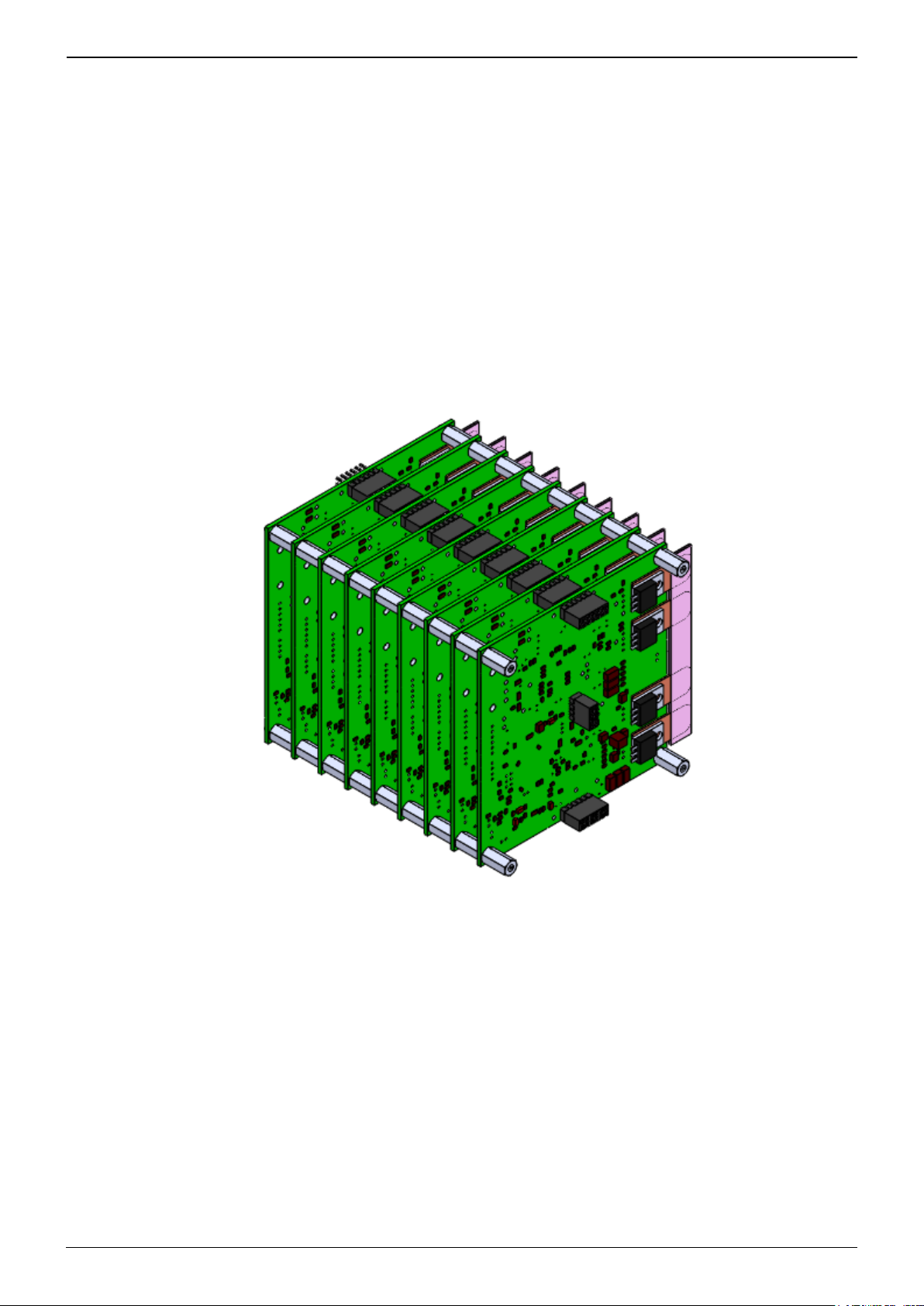
designed to the same template so that they can be stacked together to form a board-to-board bus
without the use of an additional backplane. An example of this stacking is shown below in figure 1.
Fig. 1: ICE daughter modules stacked together.
Each PCB has common locations for mounting holes, board-to-board interconnects, I/O connectors,
and heatsinking tabs. Once the boards are stacked together, each board can be addressed and
communicated with through a serial I2C bus (see this page for I2C details). Each daughter board can
have a specific I2C address set via dip switches on each circuit board and the master controller (ICE-
MC1) can route commands directly to each board. The master controller also routes and manages the
power bus going to each board. Up to 8 I2C addresses can be assigned, allowing up to 8 daughter
boards to be connected to a single master controller (for a total stack of 9 circuit boards). In addition
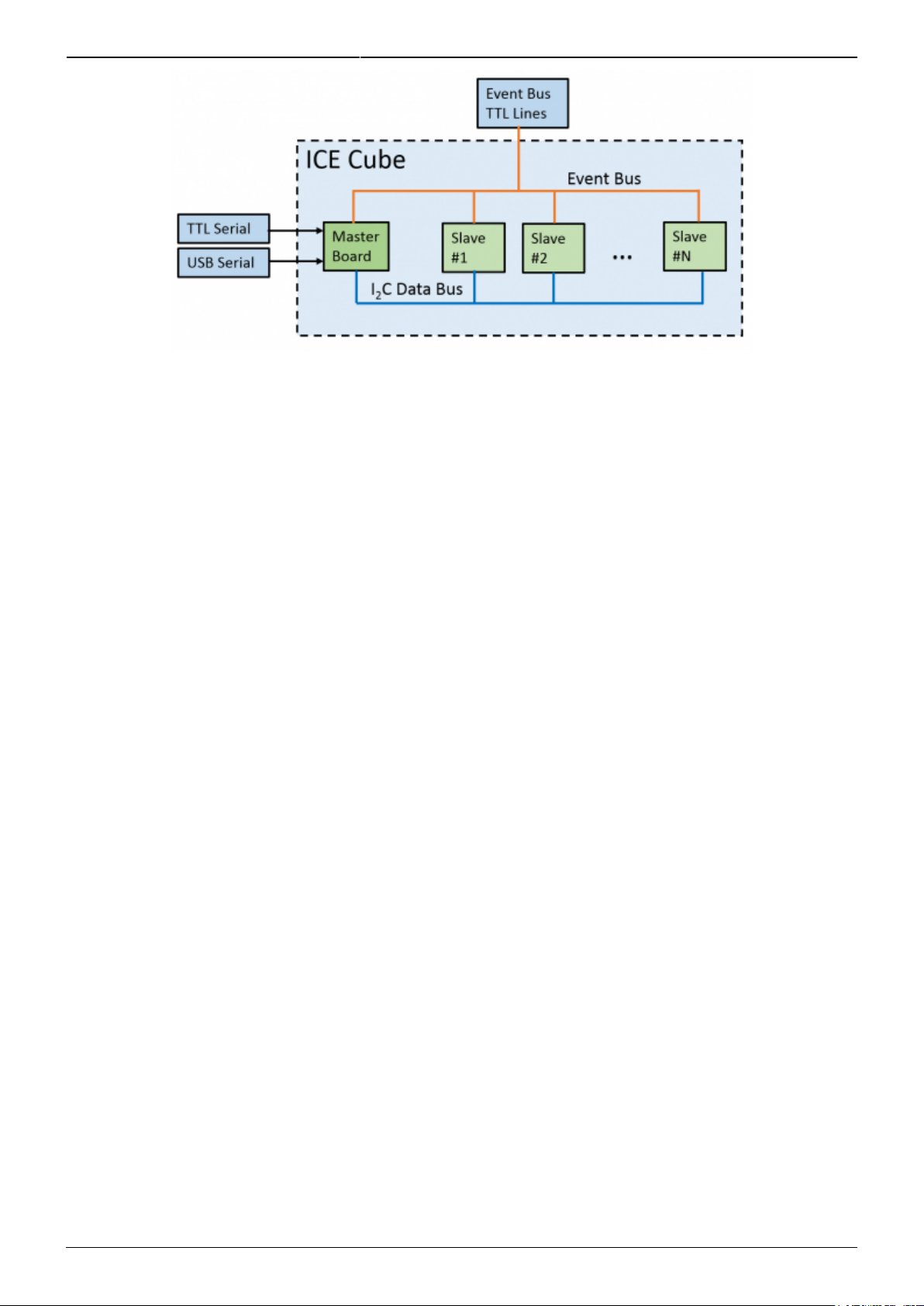
to the I2C communications bus, there are global event trigger lines that are routed directly to every
circuit board. These global trigger lines form the Event System, which allows high-speed triggering of
pre-defined behavior through TTL without the overhead of USB or serial communications. The block
diagram in figure 2 shows how master-daughter and event system communication is routed.
Product Manuals - http://www.vescent.com/manuals/
Last update: 2014/07/30 18:37 ice:oem_integration http://www.vescent.com/manuals/doku.php?id=ice:oem_integration
Fig. 2: Communication system block diagram.
Considerations for integrating the ICE Platform stack in an OEM situation are detailed in the remainder
of this document. Important key points include deciding on the type and quantity of daughter
modules to use and how that relates to the overall power budget for both the power supply and the
maximum currents that can be routed through the power bus. The mechanics of mounting the circuit
boards and designing a thermal management system must also be designed. Connections for
communication and I/O from the circuit boards to the integrator's system are also detailed in the
document.
Can't find what you are looking for? A forum has been established for Q&A and information
dissemination. We invite you to join.
Power Requirements
Power Entry
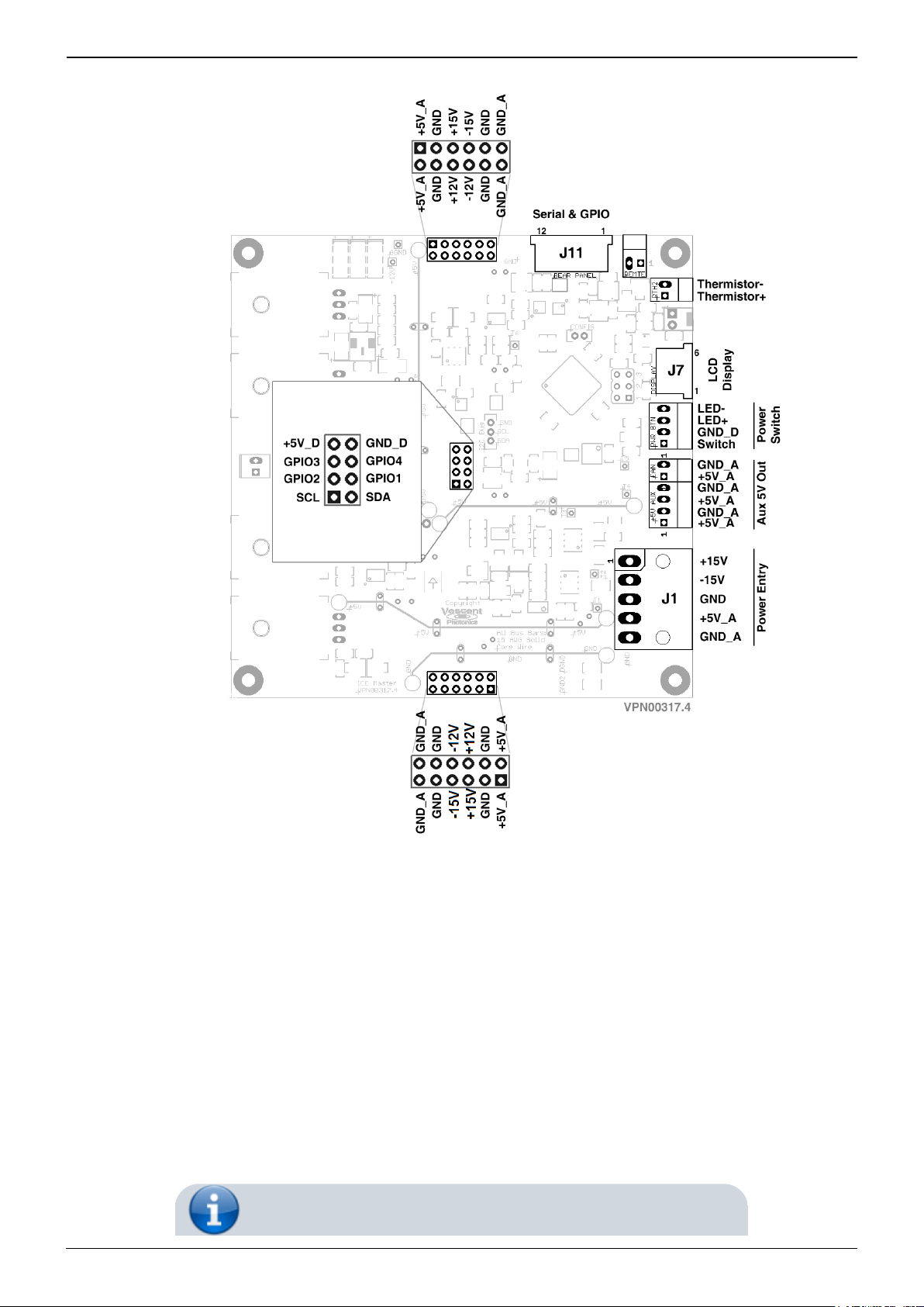
Power needs to be supplied to the power bus headers on all ICE circuit boards. These headers and
respective supply voltages are shown in figure 3. The ICE master controller board (ICE-MC1) takes a
single power entry point and distributes power to these headers. The master controller board also
provides fault protection, power sequencing, in-rush current protection, and over-current protection in
addition to distributing power. It is highly recommended to only power the ICE board stack through an
ICE master controller for these functions. If power is applied by the OEM integrator directly to the ICE
power bus, the ICE power sequencing and protection requirements in this document must be strictly
followed to avoid damaging connected ICE modules.
http://www.vescent.com/manuals/ Printed on 2019/05/01 00:16
2019/05/01 00:16 3/17 OEM Integration Guide
Fig. 3: ICE-MC1 Master and Control Board connector schematic (as viewed from component side).
Power Entry Through ICE Master Controller
Power is provided at J1 (Molex P/N: 0039303056). Pin definition shown in figure 3. The return current
path for +5V_A is GND_A. This wiring connected to this return path should be capable of carrying the
maximum current of the +5V_A line. Since the master controller handles all power sequencing
requirements, the power connections for 5V_A, +15V, and -15V can be applied in any order so long as
both ground connections have been established. The master controller will not turn on if any of the
required voltages are not present or are out of range. These power entry inputs are also reversepolarity protected. When the master controller enables power to the daughter boards via the power
bus, power is in-rush current limited to less than 10A on the 5V_A line and 3A on the 15V lines.
Product Manuals - http://www.vescent.com/manuals/

Last update: 2014/07/30 18:37 ice:oem_integration http://www.vescent.com/manuals/doku.php?id=ice:oem_integration
The signals GND and GND_A are shorted together on the
circuit board through a jumper, but this can be removed.
Power Entry Via Direct Power Bus Connection
Direct power connection to the power headers on ICE
daughter modules is discouraged due to possible damage to
modules if proper power sequencing is not followed.
Power can be provided directly to the internal power bus headers if no master controller is used in the
system, but this is highly discouraged as the power requirements are much more strict in order to
prevent damaging system components. There are three power bus connectors shown in figure 3 that
utilize 0.1 inch double row board to board headers. The 6×2 headers (Samtec PN: ESQ-106-13-T-D) on
either side of the pcb carry 5V_A, +15V, +12V, -12V, -15V power rails and GND_A and GND signal.
Both of the headers must be powered by the same power rails and be connected to the same
grounds. The signal name GND_A is the return current path for the 5V_A rail which provides high
current to daughter modules which require it (such as the ICE-QT1). The 4×2 header (Samtec PN:
ESQ-104-13-T-D) in the center of the pcb carries the digital communications bus and +5V_D power
rail. The 5V_D power rail is designed to provide power to noisier digital components without
contaminating the other analog power rails. This power rail can be “starred” off of the 5V_A line. All
ground connections (GND, GND_A, GND_D) are intended to be starred at the power supply. The power
sequence for turning on and off each voltage rail must be followed as described in the power
sequencing section or damage will occur.
Power Draw by Module
The power supply capacity for the supply used to power the ICE stack must be sized appropriately to
handle expected power draw for the modules selected. Current draw is listed in the specifications for
each of the daughter modules. The typical values indicate the quiescent current draw, and the max
values represent worst case power draw depending on the functionality of the board. For example,
the ICE-QT1 quad temperature controller has a maximum expected current draw on the 5V_A rail that
depends on the maximum current supplied to thermo-electric coolers (TEC's). The maxiumum current
here depends on what the user sets the current limit to for each temperature controller section. The
max spec given is based on the highest current limit being set for each section, and the power supply
should be capable of supply that current unless those current limits are set lower. Another example
are the ICE-CS1 and ICE-CP1 modules, both of which include a laser current controller. The current
draw on the +15V depends on the laser current output, which has a maximum output current that can
be used to determine total current draw. This is detailed in the specifications charts on the respective
product pages for all these modules.
The ICE-MC1 master controller and ICE power bus have a maximum amount of current that can be
routed. This is specified in the maximum power consumption specification on the ICE-MC1 product
page. When choosing how many and which type of each daughter module a master controller can
support, the expected current draw of all daughter modules must not exceed the maximum power
consumption specification for the master controller. For example, the master controller and ICE power
http://www.vescent.com/manuals/ Printed on 2019/05/01 00:16
2019/05/01 00:16 5/17 OEM Integration Guide
bus can only distribute a maximum of 10 amps on the 5V_A rail. If three ICE-QT1 temperature
controllers were chosen as daughter modules, and all the TEC current limits were left at maximum,
the three modules could potentially draw 12 amps. This would exceed the capacity of the power bus
and master controller. The master controller provide over-current protection, so it would shut down
power to the daughter modules and enter a fault condition if 12 amps were attempted to be drawn
from the 5V_A rail.
When choosing how many and which type of each daughter
module a master controller can support, the expected
current draw of all daughter modules must not exceed the
maximum power consumption specification for the master
controller.
Power Sequencing
Power sequencing is not required if using the ICE-MC1
master controller as it handles sequencing and startup
commands automatically.
The ICE power bus that distributes power to all daughter modules must have each voltage rail
properly sequenced when turning power on and off. The ICE-MC1 master controller automatically
takes care of this power sequencing to protect daughter modules. If power is being applied directly to
the power bus by the OEM integrator, the power sequencing outlined in this section must strictly be
followed to prevent damage to the daughter modules. Between each step, an appropriate amount of
settling-time should given for the previous power rail to settle (fully turn on or off) before proceeding
to the next step. This is generally at least 100 milliseconds for most power supplies and voltage
regulators. The I2C broadcast commands are detailed in the communications section, but are included
here to show the timing of when the commands should be sent. These commands are required to be
sent for safe shutdown and proper operation of ICE daughter modules.
The I2C System Ready and Shutdown commands are required
to be sent for safe shutdown and proper operation of ICE
daughter modules.
A delay of 100 ms (unless otherwise noted) is a generally
sufficient time to wait between each power sequence step to
allow the power supply to settle.
Product Manuals - http://www.vescent.com/manuals/
Last update: 2014/07/30 18:37 ice:oem_integration http://www.vescent.com/manuals/doku.php?id=ice:oem_integration
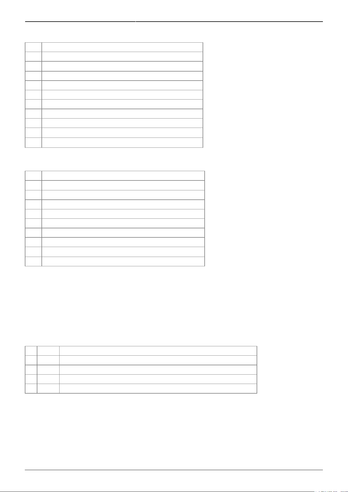
Power On Sequence
Step Action
1 Enable 5V_D rail
2
Enable external 3.3V pull-up resistors on I2C and GPIO
1)
3 Enable +15V rail
4 Enable +12V rail
5 Enable -15V rail
6 Enable -12V rail
7 Enable 5V_A rail
8 Wait 2.5 seconds
9
Broadcast System Ready I2C command
10
Broadcast Interlock Off I2C command
2)
3)
Power Off Sequence
Step Action
1
Broadcast Shutdown I2C command
4)
2 Wait 1 second
3 Disable 5V_A rail
4 Disable -12V rail
5 Disable -15V rail
6 Disable +12V rail
7 Disable +15V rail
8
Disable external 3.3V pull-up resistors on I2C and GPIO
5)
9 Disable 5V_D rail
Power Button
The ICE-MC1 master controller is designed to allow a push switch to be wired up to turn on and
shutdown the ICE stack. There is a 4-pin Molex connector (Molex PN: 22-05-3041) which allows for
connection to a “OFF-Mom” style (normally off, momentary on) push switch and power for an LED to
indicate power state. The pin diagram is shown in figure 3, labeled as “Power Switch”. For reference,
the pin definition is shown in table 1.
Pin Name Function
1 Switch Connect to one terminal of push switch
2 GND_D Connect to other terminal of push switch
3 LED+ Provides 5V to connect to positive terminal of LED
4 LED- Connected to ground (GND_D) through 249Ω resistor and transistor
Tab. 1: Pin definitions for power switch connector
The momentary push switch should short to GND_D (provided on the connector) when activated. The
master controller handles switch debouncing and will toggle the system power on and off with each
press of the switch. For testing and toggling system power without an external switch connected,
there is a SMD tactile switch located on the underside of the master controller circuit board that is
wired in parallel to the external switch.
http://www.vescent.com/manuals/ Printed on 2019/05/01 00:16
 Loading...